Wiring harness design in CATIA V5 - 3D modeling Week 5 & 6 Challenge
The harness layout is routed and connected in electrical workbench, as per given layout
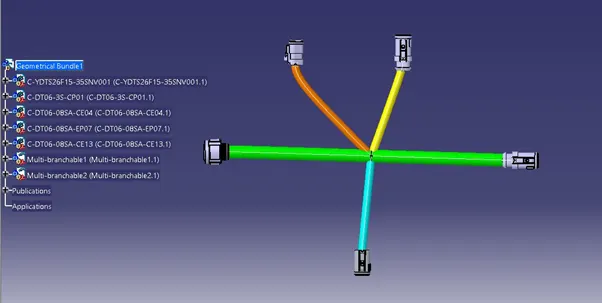
Harness A
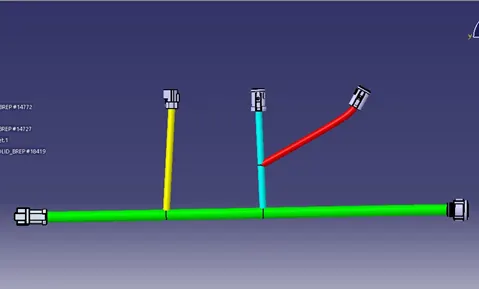
Harness B
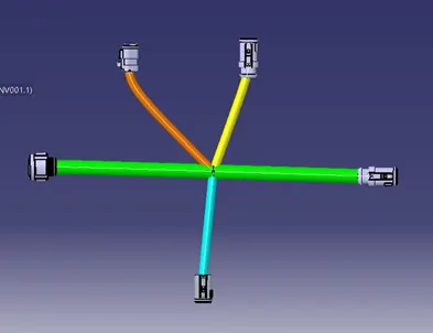
Harness assembly (A):
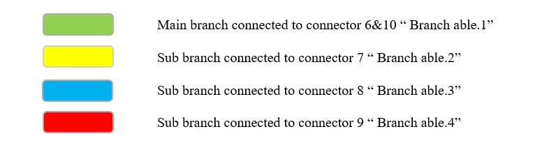
Colour coding:
Design layout: 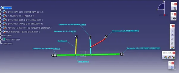
Bundle continuity of harness assembly, A. This will check the bundle connection; the image below shows the true value of branches which means all the bundles are fully connected.
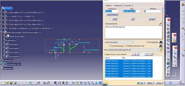
To check the bundle warning.
The bundle warning sign shows a yellow exclamation mark (!) on the multi-branch able product. And on bundle segment. Bundle warning is also highlighted as a red mark in front of the bend radius in-branch definition, which justifies the inappropriate bend radius of the branch. Below images of harness assembly, A shows no bundle warning
No yellow exclamation mark in the product and bundle segment 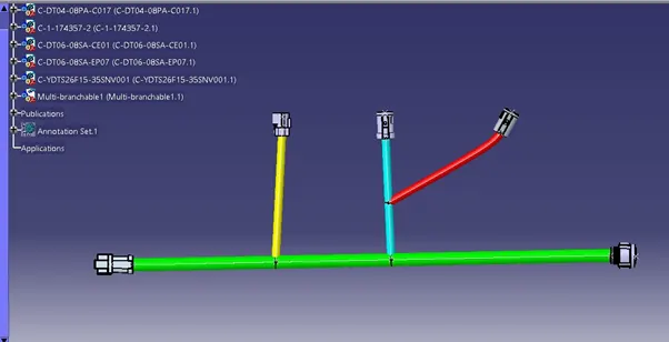
Harness assembly A, generated as a CAT.PART FROM PRODUCT. And saved as STP file. 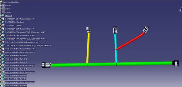
Harness assembly B:
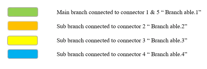
Colour coding:
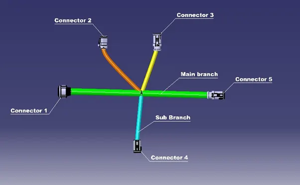
Design layout of harness B:
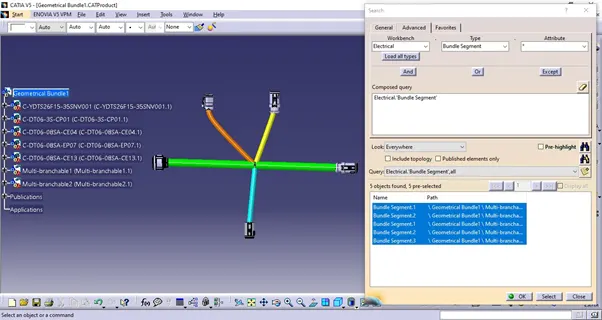
Bundle continuity of harness assembly, A. This will check the bundle connection; the image below shows the true value of branches which means all the bundles are fully connected.
To check the bundle warning.
The bundle warning sign shows a yellow exclamation mark (!) on the multi-branchable product. And on bundle segment. The bundle warning is also highlighted as a red mark in front of the bend radius in-branch definition, which justifies the inappropriate bend radius of the branch. Below are images of the harness assembly, A shows no bundle warning
· No yellow exclamation mark in the product and bundle segment
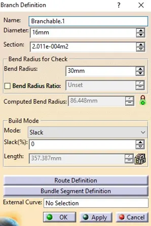
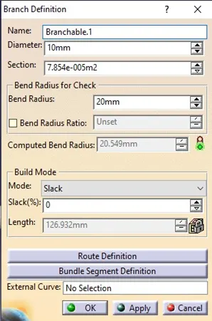
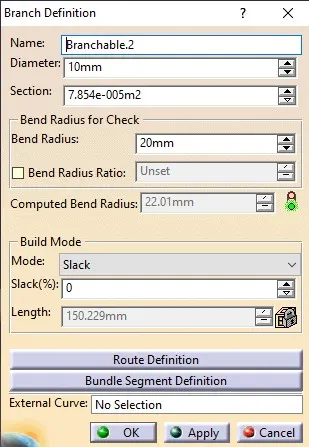
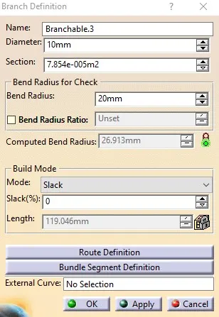
· No red mark in front of the “Computed bend radius” in the branch definition of branches.
· Branchable.1, Branch able.2, Branch able.3, Branch able.4
· The Below images show the branch details and branch diameter.
 |
 |
 |
 |
Harness assembly A, generated as a CAT.PART FROM PRODUCT. And saved as STP file.