Wiring harness design in CATIA V5 - 3D modeling Week 7 Challenge
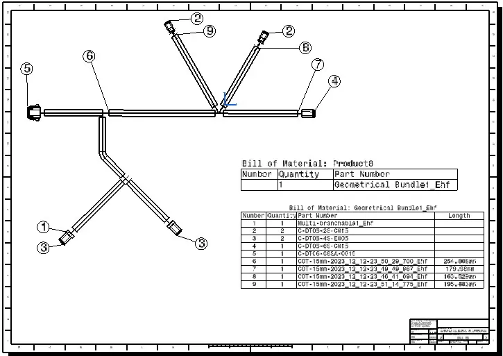
Q1. Flatten the harness assembly completed in the “ week 4 challenge”. Place the flattened view on the drawing sheet. Ensure bundles with protective coverings has different visuals on the drawing view.
OBJECTIVE:
- To flatten the wire harness assembly completed in the week 4 assignment.
- To orient the wire bundle as shown in the layout.
- To place the flattened view on a drawing sheet.
- To ensure bundles with protective coverings has different visuals on the drawing view.
Electrical harness assembly design
Step to involve electrical harness assembly
Import the all the electrical parts from the TE.com website
Imported parts are
1. C-DT06-2S-C015
2. C-DT06-4s-C015
3. C-DT06-6S-C015
4. C-DT06-08SA-C015
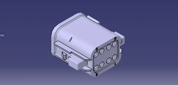
C-DT06-08SA 1
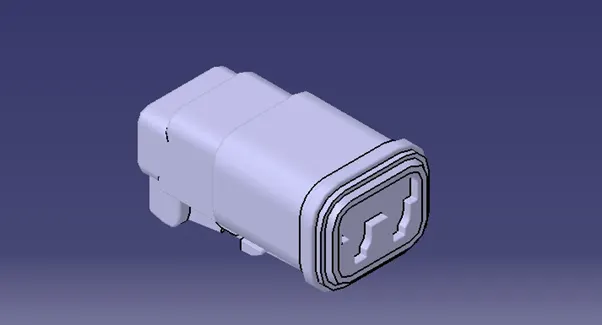
C-DT06-6S 1
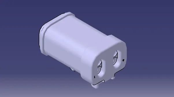
C-DT06-2S 1
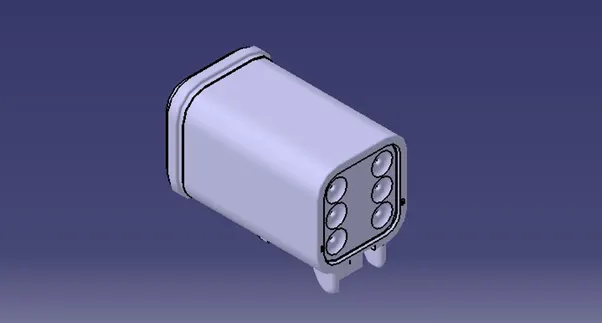
C-DT06-4S 1
Import the all the part to Catia. Then create bundle connection point, Connector connection point, cavity connection point and add axis system to these points.
Go to Equipment and system -----> Electrical harness discipline -----> Electrical part design
Once enter in to the electrical part design work bench defines a part as an electrical part by clicking the define part icon.
In the same work bench define the electrical connection point and bundle connection point.
Assemble all the electrical parts in the assembly work bench, and start the electrical harness design.
Assembly definition:
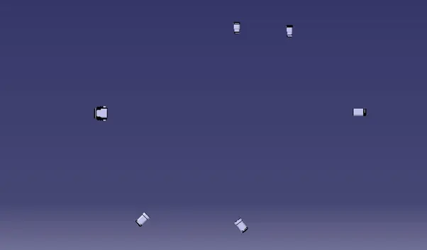
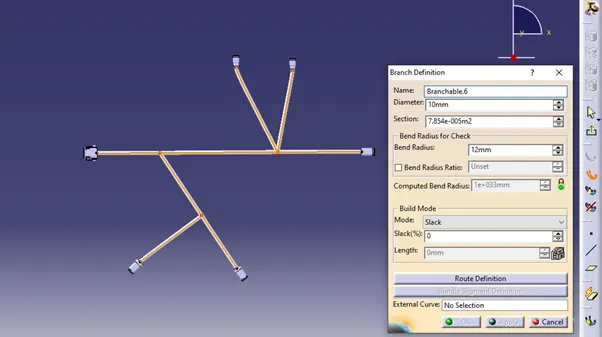
Rooting definition:
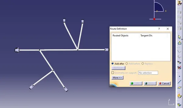
To create protection cover, go to the electrical part design workbench and select the protection cover icon, where enter the inner diameter, bend radius and thickness.
Electrical protection cover creation
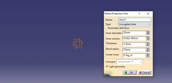
After entering all the required data click on the OK button to create the protection cover
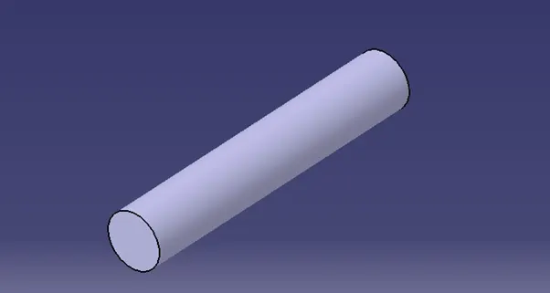
Save this file in the electrical catalog. Apply the protection cover for rooting definition in the electrical assembly workbench.
While applying the protection cover make sure that the inner diameter of the protection cover should be greater than the bundle diameter
Once the harness assembly is finished, open the harness flattening module. Initially, we need to set the harness flattening parameters. Set the proper parameters for harness flattening.
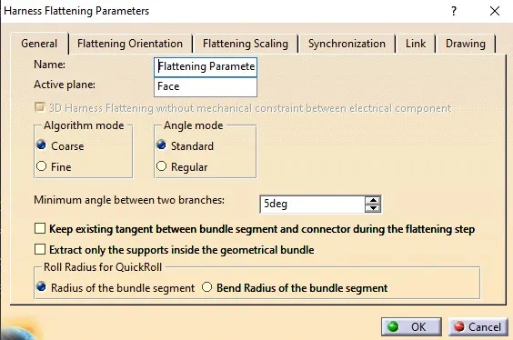
Harness Flattening:
After completion of parameter setting insert the harness assembly to the current module. Click on the flatten command to flatten the harness assembly. 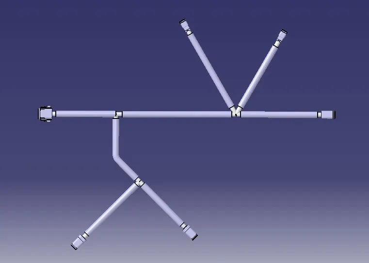
The above image shows the flattening of the harness assembly.
Harness Drafting:
After completion of the flattening oper drafting module. select the front face of the assembly, in the parameter setting select the double line for the corrugate tube and the single line for the wire harness