Week 10 - Challenge 2- Attachment Feature Creation (Dog House)
Draft Analysis:
Draft analysis is done by taking the tooling axis line, which is created by bisecting line method
Step 1: Create a point on the surface by using a point on the surface method
Step 2: Create bisecting line by using bisecting method
Step 3: Drawn line using the bisecting method command
Step 4: After creating the line click on the Feature draft analysis
Step 5: Select the compass to create to define the new current draft direction
Step 6: Click on any surface of the part to the analysis
The red color indicates draft angle is perpendicular to the tooling axis
In our parts, there is no red color indication during the draft analysis
The green color indicates that there is a 2-degree surface drafted to the tooling axis.
Green color : Draft value above 3degree
Red color : Draft angle equals to 0 degree
Blue color : Draft angle below 3 degree
Draft analysis is a process of evaluating the angles of a part's geometry and the direction of its features relative to its mold's parting line. This analysis helps identify any issues or potential problems that may arise during the manufacturing process. For example, if a part's angle is too steep, it may not be possible to eject it from the mold, resulting in a defective part.
Step for draft analysis :
Step 1: Switch customize view parameter mode to material
Step 2: To perform draft analysis. Go to Insert > Analysis > Feature draft analysis
Step 3: Click on the compas icone and align it with the tooling axis and click on the surface of the part, we will get our result. Below image shows the draft anslysis result.
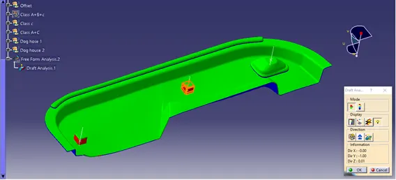
From the above figure green color indicates that draft angle is more than 30 to the tooling axis which is most required for tooling feasibility.
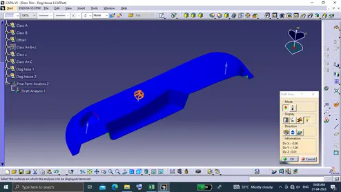
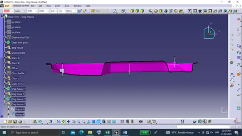
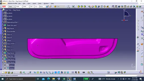
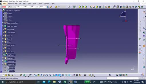
Below images shows the fully draft analysis.
Front view :
Top view:
Side view:
ISO view:
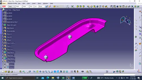
Tooling Axis Creation:
Tooling Axis
Tooling axis creation is the process of creating a toolpath for a CNC machine to follow when cutting apart. The tooling axis refers to the direction in which the cutting tool moves in relation to the part being machined. The tooling axis is defined by the CNC program, and it determines the shape and accuracy of the final part.
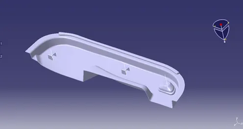
Dog house
The dog house is an engineering feature used in the plastic trim design. Which are used as supporting members. It provides sufficient strength to the screw boss which is mounted on it. Which is drafted at some angle to prevent damage during the ejection time. Dog house and other engineering features are built on B-surface.
Step involved to create a dog house
Step 1: Creating a base diagram
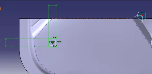
Step 2: Extrude the baseline parallel to tooling
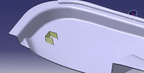
Step 3: Create a top surface the height of the surface is dependent on user input data
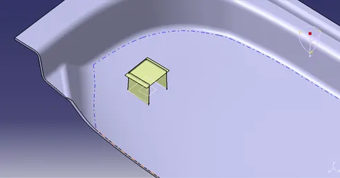
Step 4: Trim the extruded surface and to surface and apply fillet on the corners fillet radius 0.25mm
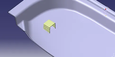
Step 5: After completing trimming go to part design and apply the thick feature to the base surface thickness is 2mm
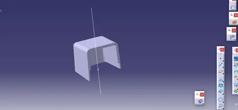
Step 6: Creating intersection part wall
Offset the inner side surface of the dog house lesser than 40% of the main wall stock and the height should be 3-6mm.
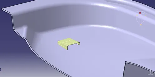
Step 7: Go to the part design workbench and split the contact surface from the dog house using the slit command
Design consideration for plastic
- Wall thickness
Wall thickness: (0.7) X (Nominal thickness of the plastic material)
- Corner radii
Corner radii: (0.6-0.75) X (Nominal thickness of the plastic material)
- Draft angle
Draft angle: 2-3degree
- Fillets
Fillet on theinner side : 0.25 X Thickness of the plastic material
Fillet on outer side : 1.25 X Thickness of the plastic material
Fillet on coring edge : 0.25 X Thickness of the plastic material
Coring thickness : 0.4 X Thickness of the plastic material
Conclusion:
Dog house was created by considering following design guideline