Week 1- Mixing Tee
This assignment aims to evaluate the mixing effectiveness of a Tee joint with two different outlet pipe lengths, namely small and long.
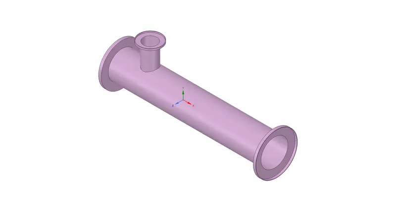
The required Tee geometry is provided, and the interior volume for CFD analysis is extracted as shown below.
Tee geometry with shorter outlet pipe:
Extracted volume:
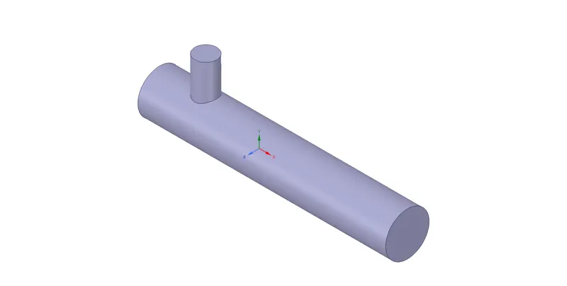
The meshing of the geometry is performed in ANSYS fluent module. First, a default mesh is generated for the analysis, followed by a mesh-independent study.
The problem is defined below:
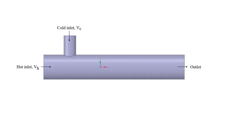
The temperature and velocities of the fluid entering the hot and cold inlets are different and are described in the table below.
| Inlet type | Temperature (Centigrade) | Velocity (`m/s`) |
| Cold | 19 | 6 |
| Hot | 36 | 3 |
Momentum ratio, defined as `(V_c)/(V_h)` is varied as 2 & 4 with hot inlet velocity fixed at 36 `m/s` resulting in the cold velocity as 6 & 12 `m/s` respectively.
As shown in the previous image, the boundary conditions are named appropriately, with velocity inlets, the pressure outlet, and the outer surface as a wall.
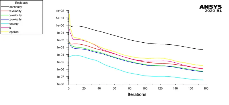
The energy option is selected with K-epsilon (realizable, standard wall functions) as the turbulence model. All other options are used as default with the residuals decreased than the default for a better solution.
New definitions like area-weighted average and standard deviation of the outlet temperature are defined to evaluate the mixing efficiency. A mesh-independent study is performed for the shorter outlet pipe by changing the element size, and the results are tabulated below.
For shorter outlet pipe with momentum ratio = 2:
| Element size (m) | Tetrahedral elements | Area weighted outlet temperature (Centigrade) |
| 0.010219 | 12759 | 30.202037 |
| 0.005 | 14400 | 30.235698 |
| 0.0025 | 60959 | 30.306484 |
| 0.0015 | 212192 | 30.343242 |
The analytical values for the outlet temperature, calculated for different momentum ratios, are shown below.
| Momentum ratio |
Outlet temperature (Centigrade) |
| 2 | 30.32238 |
| 4 | 27.4876 |
From the above tables, the error in the outlet temperature is less for the fourth case (0.0015 m as the element size). Hence, this mesh is considered for the study.
A different turbulence model (K-`omega` SST) is also tested, and the outlet temperature is listed below.
| Turbulence model |
Outlet temperature (Centigrade) |
|
K-`epsilon` (realizable, standard wall functions) |
30.343242 |
| (K-`omega` SST) | 30.49841 |
The outlet temperature (area-weighted) is closer to the theoretical value for the K-`epsilon` model. So, this turbulence model is used for the study.
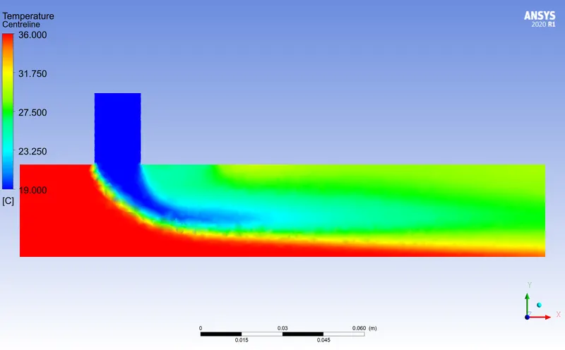
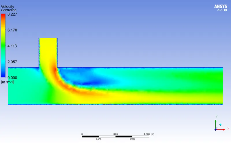
Shorter outlet pipe, momentum ratio = 2:
Convergence plot
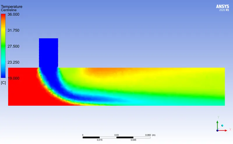
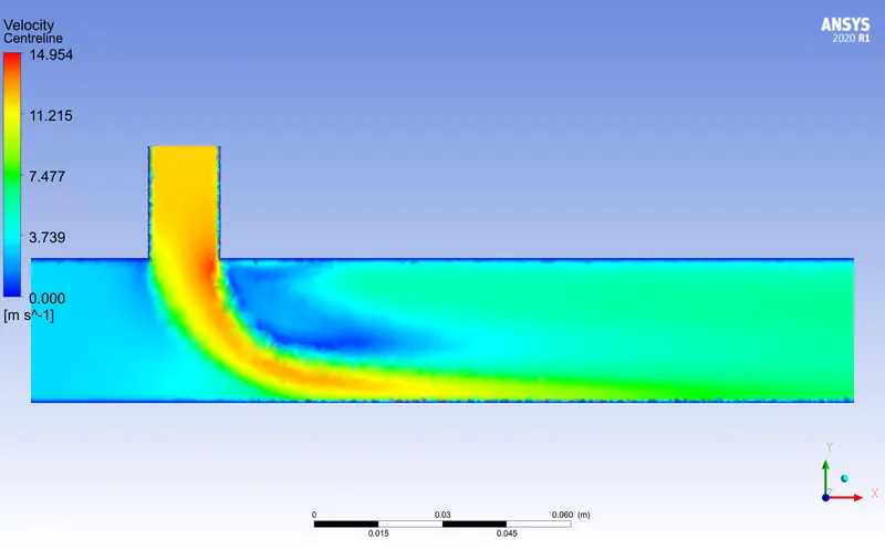
Temperature & velocity plot along the axial plane
Shorter outlet pipe, momentum ratio = 4:
Longer outlet pipe, momentum ratio = 2:
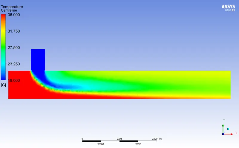
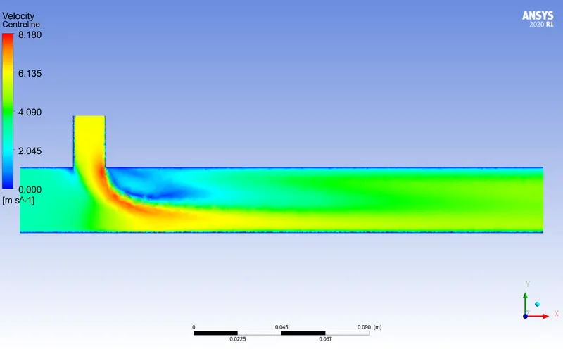
Shorter outlet pipe, momentum ratio = 4:
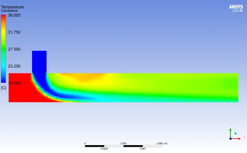
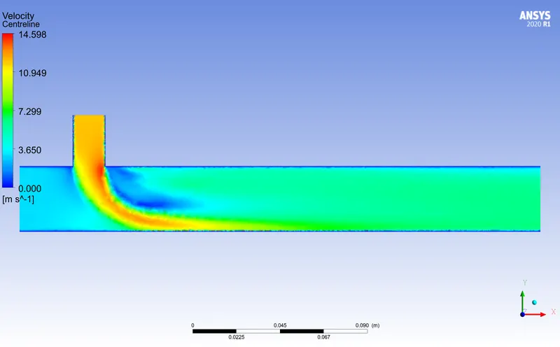
The results are summarized in the following table
| Geometry | Momentum ratio | Area-weighted outlet temperature |
| Short | 2 | 30.343242 |
| Long | 2 | 30.442305 |
| Short | 4 | 27.580206 |
| Long | 4 | 27.500309 |
The centreline temperature variation for all four cases is plotted below.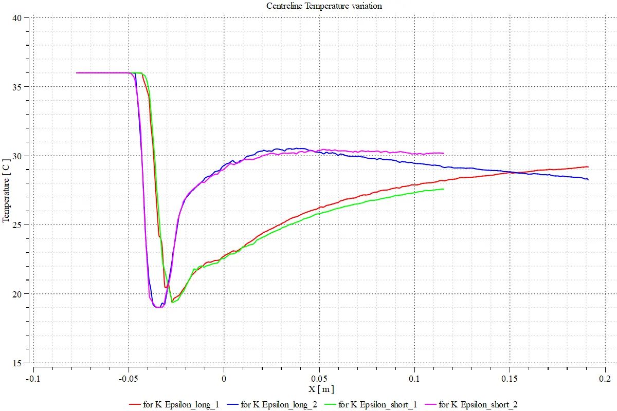
Cases 1 & 2 represent flows with momentum ratio 2 & 4 respectively.
In short, it can be concluded that increasing the outlet pipe length indeed increases the mixing efficiency even though the increase with respect to a shorter outlet pipe is less.