To Perform Buckling analysis on a cyclonic separator stand and find the optimum position and thickness for the stiffener
OBJECTIVE :-
To Perform Buckling analysis on a cyclonic separator stand and find the optimum position and thickness for the stiffener.
FINITE ELEMENT ANALYSIS :-
The finite element method (FEM) is the most widely used method for solving problems of engineering and mathematical models. Typical problem areas of interest include the traditional fields of structural analysis, heat transfer, fluid flow, mass transport, and electromagnetic potential. The FEM is a particular numerical method for solving partial differential equations in two or three space variables .To solve a problem, the FEM subdivides a large system into smaller, simpler parts that are called finite elements. This is achieved by a particular space discretisation in the space dimensions, which is implemented by the construction of a mesh of the object: the numerical domain for the solution, which has a finite number of points. The finite element method formulation of a boundary value problem finally results in a system of algebraic equations. The method approximates the unknown function over the domain. The simple equations that model these finite elements are then assembled into a larger system of equations that models the entire problem. The FEM then uses variational methods from the calculus of variations to approximate a solution by minimizing an associated error function.
FEM is best understood from its practical application, known as finite element analysis (FEA). FEA as applied in engineering is a computational tool for performing engineering analysis. It includes the use of mesh generation techniques for dividing a complex problem into small elements, as well as the use of software program coded with FEM algorithm. In applying FEA, the complex problem is usually a physical system with the underlying physics such as the Euler-Bernoulli beam equation, the heat equation, or the Navier-Stokes equations expressed in either PDE or integral equations, while the divided small elements of the complex problem represent different areas in the physical system.
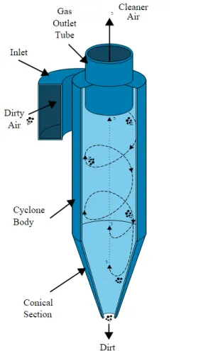
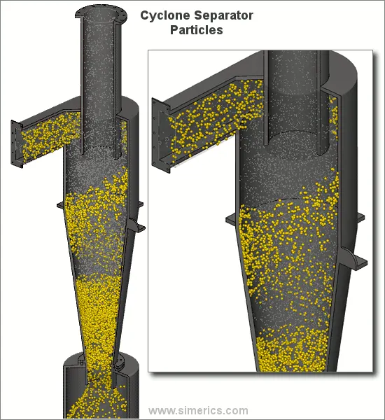
Cyclone separators or simply cyclones are separation devices (dry scrubbers) that use the principle of inertia to remove particulate matter from flue gases. Cyclone separators is one of many air pollution control devices known as precleaners since they generally remove larger pieces of particulate matter. This prevents finer filtration methods from having to deal with large, more abrasive particles later on. In addition, several cyclone separators can operate in parallel, and this system is known as a multicyclone.
It is important to note that cyclones can vary drastically in their size. The size of the cyclone depends largely on how much flue gas must be filtered, thus larger operations tend to need larger cyclones. For example, several different models of one cyclone type can exist, and the sizes can range from a relatively small 1.2-1.5 meters tall (about 4-5 feet) to around 9 meters (30 feet)—which is about as tall as a three story building.
BUCKLING IN CYCLONE SEPERATOR STAND :-
In engineering, buckling is the sudden change in shape of a structural component under load such as the bowing of a column under compression or the wrinkling of a plate under shear. If a structure is subjected to a gradually increasing load, when the load reaches a critical level, a member may suddenly change shape and the structure and component is said to have buckled.
Buckling may occur even though the stresses that develop in the structure are well below those needed to cause failure in the material of which the structure is composed. Further loading may cause significant and somewhat unpredictable deformations, possibly leading to complete loss of the member's load-carrying capacity. However, if the deformations that occur after buckling do not cause the complete collapse of that member, the member will continue to support the load that caused it to buckle. If the buckled member is part of a larger assemblage of components such as a building, any load applied to the buckled part of the structure beyond that which caused the member to buckle will be redistributed within the structure. Some aircraft are designed for thin skin panels to continue carrying load even in the buckled state.
PROCEDURE :-
CASE 1 :- Without Stiffener
- Create the Model of the Cyclone Seperator and also Create the Stand and Assemble all the Parts .
- Now Go to the Simulation -> New study -> Static -> Ok
Now, Suppress the Cyclone seperator parts which are not used in the FEA Simulation.
- Apply Material -> Alloy steel
- Apply Fixtures -> Fix -> Stand base Part
Apply External load -> Force-> 150000 Newton
Meshing -> Create mesh -> Fine
SIMULATION RESULT :-
We can see that after Finite element analysis of the Cyclone Seperator Stand we can see that the Factor of Safety is 9.35 which is very small due to which there is large deflections and stress.
CASE 2 :- With Stiffener
- Create the Model of the Stiffener and Extrude it for about thickness 75mm and of offset of 1 metre.
- Suppress the unused parts in the New Simulation Static Study.
- Apply Material -> Alloy Steel -> Apply
- Apply Fixtures -> Fix -> Stand base Part
- Apply External load -> Force -> 150000 Newton
Apply Mesh -> Create Mesh -> Fine
SIMULATION RESULT :-
We can see that after creating an Stiffener and Finite element analysis of the Cyclone Seperator Stand we can see that the Factor of Safety is 27.569 which is very appropriate but not optimum due to which there is less deformation and stress.
CASE 3 :- Design Study for the Optimum position and Thickness of the Stiffener
- Variables
- Buckling -> Stiffener Position -> 0.25m - 1.75m with 0.25 steps
- Buckling -> Stiffener Thickness -> 0.075m - 0.1m with 0.025 steps
- Constraints
- Buckling FOS 1 -> is greater -> 25
- Goals
- Buckling FOS 2 -> Maximise
- RUN the Simulation
RESULTS :-
There are total 16 design Scenerios-
Optimum Buckling Analysis :-
Optimum result we get are,
Scenerio = 11
Position = 1 metre
Thickness = 0.1 metre
Factor of Safety = 31.565
The above result shows that at this position and Thickness of stiffener will give us least deformations and stress in the Stand which will increase its life and which make it cheap
-----------------------------------------------------------------------------------------------------------------------------