Study about Induction Machine and Analysing the Torque-Speed Characteristics of Induction Motor using Different Methods
AIM: - Detailed Study about Induction Machine and Analysing the Torque-Speed Characteristics of Induction Motor using Different Method.
OBSERVATION: -
- Detailed working and construction of Induction Machine.
- Deriving Torque Equation using Equivalent circuit of Induction Motor.
- Torque-Speed Characteristics of Induction Motor using Variable Rotor Resistance and Analysing the results.
- Torque-Speed Characteristics of Induction Motor using Variable Stator Voltage and Analysing the results.
- Torque-Speed Characteristics of Induction Motor using Variable Supply frequency with constant V/f and Analysing the results.
INDUCTION MACHINE/MOTOR: -
An induction motor (also known as an asynchronous motor) is a commonly used AC electric motor. In an induction motor, the electric current in the rotor needed to produce torque is obtained via electromagnetic induction from the rotating magnetic field of the stator winding. The rotor of an induction motor can be a squirrel cage rotor or wound type rotor.
.JPG)
Working: -
We need to give double excitation to make a DC motor to rotate. In the DC motor, we give one supply to the stator and another to the rotor through brush arrangement. But in induction motor, we give only one supply, so it is interesting to know how an induction motor works. It is simple, from the name itself we can understand that here, the induction process is involved. When we give the supply to the stator winding, a magnetic flux gets produced in the stator due to the flow of current in the coil. The rotor winding is so arranged that each coil becomes short-circuited.
The flux from the stator cuts the short-circuited coil in the rotor. As the rotor coils are short-circuited, according to Faraday’s law of electromagnetic induction, the current will start flowing through the coil of the rotor. When the current through the rotor coils flows, another flux gets generated in the rotor. Now there are two fluxes, one is stator flux, and another is rotor flux. The rotor flux will be lagging in respect of the stator flux. Because of that, the rotor will feel a torque which will make the rotor to rotate in the direction of the rotating magnetic field. This is the working principle of both single and three phase induction motors.
Stator: -
The stator is made up of various stampings with slots to carry three phase windings. It is wound for a distinct number of poles. The windings are geometrically divided 120 degrees separated. Two sorts of rotors are used in Induction motors: Squirrel cage rotor and Wound rotor. No DC field current is required to run the machine. Rotor voltage is induced in the rotor windings rather than being physically connected by wires.
Rotor: -
The rotor is the rotating part of the electromagnetic circuit. The most common type of rotor is the squirrel cage rotor. circuit R1 represent The rotor comprises of a cylindrical laminated core with axially placed parallel slots for carrying the conductors. Each slot carries a copper, aluminum, or alloy bar. The rotor of three-phase induction motors frequently is likewise implied as an anchor. The purpose behind this name is the anchor shape of the rotors used within quite early electrical devices. In electrical equipment the anchor’s winding would be induced by the magnetic field, although the rotor takes this part in three-phase induction motors.
TORQUE-SPEED CHARACTERISTICS OF INDUCTION MACHINE: -
Equivalent circuit of Induction Machine-
Equivalent Circuit of an Induction motor enables the performance characteristics which are evaluated for steady state conditions. An induction motor is based on the principle of induction of voltages and currents. The voltage and current is induced in the rotor circuit from the stator circuit for the operation. The equivalent circuit of an induction motor is similar to that of the transformer.
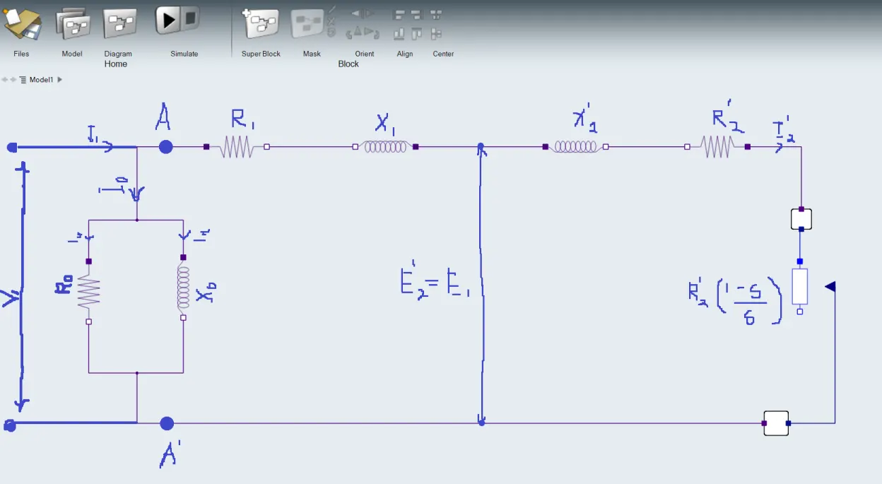
In above figure shows approximate Equivalent circuit of Inductoion Motor, in which the voltage is applied by the voltage source to the motor based on the phase. The Simplified Induction Motor block represents the electrical and torque characteristics of an induction motor powered by an ideal AC supply. Stator and Rotor are the main pans of the Induction motor current flows to the stator resistance which is less than the rotor resistance. Slip occurs if the force is more and which obeys the the condition like w_s > W_r. In equivalent circuit R1 represents, the resistance of the stator winding and X1 the stator leakage reactance (flux that does not link with the air gap and rotor). Magnetising reactance required to cross the air gap is represented by Xm and core losses (hysteresis and eddy current) by Rc. An ideal transformer of N1 and N2 turns respectively represents the air gap. For the rotor side, the induced emf is affected by the slip (as the rotor gains speed, slip reduces and less emf is induced). The rotor resistance and reactance are represented by R'2 and X'2, with X'2 being dependent on the frequency of the induction rotor emfs.
The approximate circuit is based on the assumption that V1 = E1 = E’2. In the above circuit, the only component that depends on the slip is the resistance. All the other quantities are constant. The following equations can be written at any given slip s is as follows:-
Impedance beyond AA’ is given as
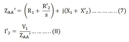
Putting the value of ZAA’ from the equation (7) in the equation (8) we get
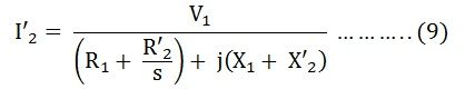
Therefore,
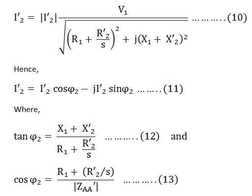
No load current I0 is
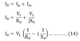
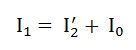
Total stator current is given by the equation shown below.
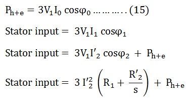
Total core losses are given by the equation shown below.
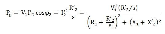
Air gap power per phase is given as
Rotor Slip (s) is defined in terms of the mechanical rotational speed w_s, the number of pole pair p, and electrical supply frequency w by: -
s = 1 - p*w_s/w
This means that the slip is one when starting, and zero when running synchronously with the supply frequency.
Developed torque is given by the equation shown below.
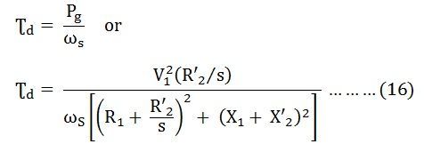
The above equation is the torque equation of an induction motor. The approximate equivalent circuit model is the standard for all performance calculation of an induction motor.
Calculation: -
3 phase, 50Hz Induction motor, represented by equivalent circuit constants X1 = X'2 = 0.1 Ohm and R1 = R'2 = 0.2 Ohm is operated at half of rated voltage and frequency. Calculate the ratio of starting torque at half voltage and frequency to rated values.
==> Given: -
Frequency = 50Hz
X1 = X'2 = 0.1 Ohm
R1 = R'2 = 0.2 Ohm
V = V/2 (Calculated for half rated voltage and frequency)
w_s = 2*pi*N_s
N_s = (120*Frequency)/p (number of pole pair)
==> Starting Torque for Rated Voltage and Frequency
T = (3*(V^2)*R'2)/(w_s*((R1 + R'2)^2 + (X1 + X'2)^2))
T = (3*(V^2)*0.2)/(2*3.14*120*Frequency/p)((0.4)^2) + ((0.2)^2)
T = (7.956e - 5)*(V^2)*p
==> Starting Torque for half Rated Voltage and Frequency
T = (3*(V^2)*R'2)/(w_s*((R1 + R'2)^2 + (X1 + X'2)^2))
T = (3*(V^2)*0.2)/(2*3.14*120*Frequency/2p)((0.4)^2) + ((0.2)^2)
T = (3.978e - 5)*(V^2)*p
The Ratio of starting torque at half voltage and frequency to rated values is,
T = 0.5 Nm
CODE: -
CASE-1 : - Matlab program to Calculate Torque-Speed Characteristics of 3-phase Induction motor using variable Rotor Reasistance
clear all
close all
clc

% TORQUE-SPEED CHARACTERISTICS OF INDUCTION MOTOR USING VARIABLE ROTOR RESISTANCE
% INPUTS PROVIDED

% Input the value of the supply voltage (V)
V1 = input('Enter the Suppy Voltage (line to line) RMS value: ');

% Input the value of the number of Poles
P = input('Enter the number of poles: ');

% Input the value of the Stator resistance (Ohm)
Rs = input('Stator Resistance: ');

% Input the Different values of Rotor Resistance (Ohm)
Rr1 = input('Enter the first Rotor Resistance: ');
Rr2 = input('Enter the second Rotor Resistance: ');
Rr3 = input('Enter the third Rotor Resistance: ');
Rr4 = input('Enter the fourth Rotor Resistance: ');
Rr5 = input('Enter the fifth Rotor Resistance: ');

% Input the value of Stator Resistance (Ohm)
Xs = input('Stator Leakage Reactance @ 50 Hz frequecny: ');

% Input the value of Rotor Resistance (Ohm)
Xr = input('Rotor Leakage Reactance @ 50 Hz frequecny: ');

% Stator Inductance (H)
Ls = Xs/(2*pi*50);

% Rotor Inductance (H)
Lr = Xr/(2*pi*50);

% Synchronous speed of the Induction motor
Wsync = 4*pi*50/P;


% CALACULATING TORQUES OF THE INDUCTION MOTOR
i = 1;

for Wrotor = 0:0.002:Wsync
    Tm1(i) = (3*(((V1^2)*Rr1/((Wsync - Wrotor)/Wsync))/((Rs + Rr1/((Wsync - Wrotor)/Wsync))^2+(2*pi*50*Ls+2*pi*50*Lr)^2))/Wsync);
 i = i + 1;
end

i = 1;

for Wrotor = 0:0.002:Wsync
    Tm2(i) = (3*(((V1^2)*Rr2/((Wsync - Wrotor)/Wsync))/((Rs + Rr2/((Wsync - Wrotor)/Wsync))^2+(2*pi*50*Ls+2*pi*50*Lr)^2))/Wsync);
 i = i + 1;
end

i = 1;

for Wrotor = 0:0.002:Wsync
    Tm3(i) = (3*(((V1^2)*Rr3/((Wsync - Wrotor)/Wsync))/((Rs + Rr3/((Wsync - Wrotor)/Wsync))^2+(2*pi*50*Ls+2*pi*50*Lr)^2))/Wsync);
 i = i + 1;
end

i = 1;

for Wrotor = 0:0.002:Wsync
    Tm4(i) = (3*(((V1^2)*Rr4/((Wsync - Wrotor)/Wsync))/((Rs + Rr4/((Wsync - Wrotor)/Wsync))^2+(2*pi*50*Ls+2*pi*50*Lr)^2))/Wsync);
 i = i + 1;
end

i = 1;

for Wrotor = 0:0.002:Wsync
    Tm5(i) = (3*(((V1^2)*Rr5/((Wsync - Wrotor)/Wsync))/((Rs + Rr5/((Wsync - Wrotor)/Wsync))^2+(2*pi*50*Ls+2*pi*50*Lr)^2))/Wsync);
 i = i + 1;
end


% PLOTTING TORQUE-SPEED CHARACTERISTICS
plot(Tm1);
hold on;
plot(Tm2);
plot(Tm3);
plot(Tm4);
plot(Tm5);
hold off;
ylabel('Torque(N-m)');
xlabel('Rotor Speed(Rad/s)');
legend('Rr1 = 0.1','Rr2 = 0.3','Rr3 = 0.5','Rr4 = 0.7','Rr5 = 0.9');
STEPS: -
- Firstly, we derive the Torque Equation of the Induction Motor from the International Journal of Engineering Research & Technology (IJERT) website research paper.
- Then we will do some calculation to calculate ratio of starting torque at half voltage and frequency to rated values.
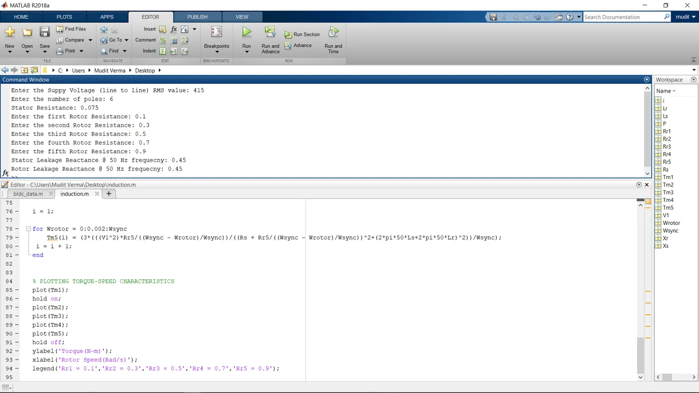
- Now, we will implement the code to calculate Torque-Speed Characteristics of Induction motor so for that firstly we will input the values that will be asked by the program after its excecution.
- Then we will calculate the Stator inductance, Rotor Inductance and Synchronous Speed of the Induction Motor.
- Then we will use looping to calculate different torques for different Rotor resistance values with respect to the Rotor Speed.
- Then we will Plot all the result in one plots using Hold on command.
- Now we RUN the Simulation.
Inputs we will provide when asked: -
RESULT: -
Torque-Speed Characteristics of 3-phase Induction motor using variable Rotor Reasistance:-
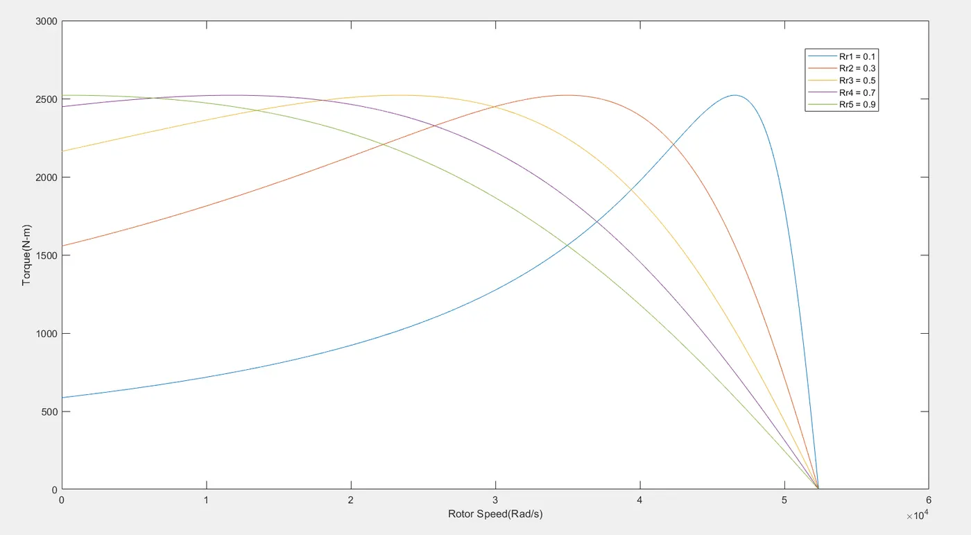
We can observe that External resistances can be connected in the rotor circuit during starting. This increases the starting torque and reduces the starting current . By making use of appropriate value of resistors, the maximum torque can be made to appear during starting. This can be used in applications requiring high starting torque. Once the motor is started, the external resistance can be cut out to obtain high torque throughout the accelerating range. As external resistances are connected, most of the I2R loss is dissipated through them thus the rotor temperature rise during starting is limited.
CASE-2 : - Matlab program to Calculate Torque-Speed Characteristics of 3-phase Induction motor using variable Stator Voltage
clear all
close all
clc

% TORQUE-SPEED CHARACTERISTICS OF INDUCTION MOTOR USING VARIABLE STATOR VOLTAGE
% INPUTS PROVIDED

% Input the Different values of the supply voltage (V)
V1 = input('Enter the first Suppy Voltage (line to line) RMS value: ');
V2 = input('Enter the second Suppy Voltage (line to line) RMS value: ');
V3 = input('Enter the third Suppy Voltage (line to line) RMS value: ');
V4 = input('Enter the fourth Suppy Voltage (line to line) RMS value: ');
V5 = input('Enter the fifth Suppy Voltage (line to line) RMS value: ');

% Input the value of the number of Poles
P = input('Enter the number of poles: ');

% Input the value of the Stator resistance (Ohm)
Rs = input('Stator Resistance: ');

% Input the values of Rotor Resistance (Ohm)
Rr = input('Rotor Resistance: ');

% Input the value of Stator Resistance (Ohm)
Xs = input('Stator Leakage Reactance @ 50 Hz frequecny: ');

% Input the value of Rotor Resistance (Ohm)
Xr = input('Rotor Leakage Reactance @ 50 Hz frequecny: ');

% Stator Inductance (H)
Ls = Xs/(2*pi*50);

% Rotor Inductance (H)
Lr = Xr/(2*pi*50);

% Synchronous speed of the Induction motor
Wsync = 4*pi*50/P;


% CALACULATING TORQUES OF THE INDUCTION MOTOR
i = 1;

for Wrotor = 0:0.002:Wsync
    Tm1(i) = (3*(((V1^2)*Rr/((Wsync - Wrotor)/Wsync))/((Rs + Rr/((Wsync - Wrotor)/Wsync))^2+(2*pi*50*Ls+2*pi*50*Lr)^2))/Wsync);
 i = i + 1;
end

i = 1;

for Wrotor = 0:0.002:Wsync
    Tm2(i) = (3*(((V2^2)*Rr/((Wsync - Wrotor)/Wsync))/((Rs + Rr/((Wsync - Wrotor)/Wsync))^2+(2*pi*50*Ls+2*pi*50*Lr)^2))/Wsync);
 i = i + 1;
end

i = 1;

for Wrotor = 0:0.002:Wsync
    Tm3(i) = (3*(((V3^2)*Rr/((Wsync - Wrotor)/Wsync))/((Rs + Rr/((Wsync - Wrotor)/Wsync))^2+(2*pi*50*Ls+2*pi*50*Lr)^2))/Wsync);
 i = i + 1;
end

i = 1;

for Wrotor = 0:0.002:Wsync
    Tm4(i) = (3*(((V4^2)*Rr/((Wsync - Wrotor)/Wsync))/((Rs + Rr/((Wsync - Wrotor)/Wsync))^2+(2*pi*50*Ls+2*pi*50*Lr)^2))/Wsync);
 i = i + 1;
end

i = 1;

for Wrotor = 0:0.002:Wsync
    Tm5(i) = (3*(((V5^2)*Rr/((Wsync - Wrotor)/Wsync))/((Rs + Rr/((Wsync - Wrotor)/Wsync))^2+(2*pi*50*Ls+2*pi*50*Lr)^2))/Wsync);
 i = i + 1;
end


% PLOTTING TORQUE-SPEED CHARACTERISTICS
plot(Tm1);
hold on;
plot(Tm2);
plot(Tm3);
plot(Tm4);
plot(Tm5);
hold off;
ylabel('Torque(N-m)');
xlabel('Rotor Speed(Rad/s)');
legend('V1 = 220','V2 = 300','V3 = 415','V4 = 550','V5 = 700');
STEPS: -
- Firstly, we derive the Torque Equation of the Induction Motor from the International Journal of Engineering Research & Technology (IJERT) website research paper.
- Then we will do some calculation to calculate ratio of starting torque at half voltage and frequency to rated values.
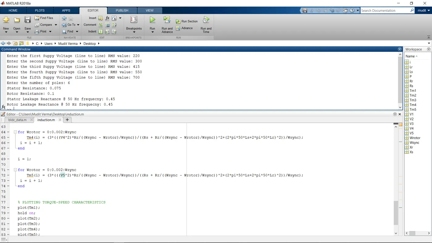
- Now, we will implement the code to calculate Torque-Speed Characteristics of Induction motor so for that firstly we will input the values that will be asked by the program after its excecution.
- Then we will calculate the Stator inductance, Rotor Inductance and Synchronous Speed of the Induction Motor.
- Then we will use looping to calculate different torques for different Supply Voltage values with respect to the Rotor Speed.
- Then we will Plot all the result in one plots using Hold on command.
- Now we RUN the Simulation.
Inputs we will provide when asked: -
RESULT: -
Torque-Speed Characteristics of 3-phase Induction motor using variable Stator Voltage:-
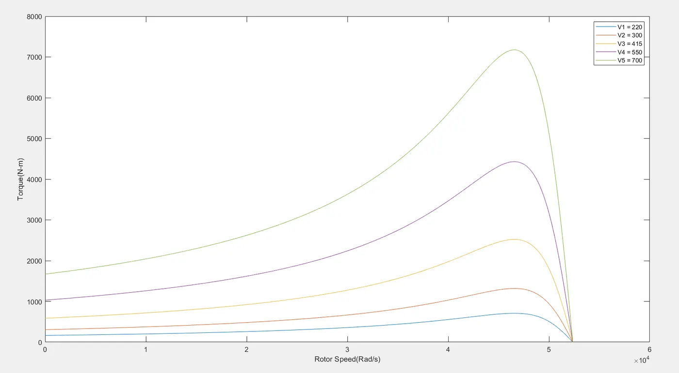
As the supply voltage is decreased, the value of maximum torque also decreases. However it still occurs at the same slip as earlier. Even the starting torque and the overall torque reduce. Thus the machine is highly underutilized. Thus this method of speed control has very limited applications.
CASE-3: - Matlab program to Calculate Torque-Speed Characteristics of 3-phase Induction motor using varying the supply frequency such that the ratio V/f remains constant
clear all
close all
clc

% TORQUE-SPEED CHARACTERISTICS OF INDUCTION MOTOR USING VARIABLE SUPPLY FREQUENCY
% INPUTS PROVIDED

% Input the value of the supply voltage (V)
V = input('Enter the Suppy Voltage (line to line) RMS value: ');

% Input the value of the number of Poles
P = input('Enter the number of poles: ');

% Input the value of the Stator resistance (Ohm)
Rs = input('Stator Resistance: ');

% Input the values of Rotor Resistance (Ohm)
Rr = input('Rotor Resistance: ');

% Input the value of Stator Resistance (Ohm)
Xs = input('Stator Leakage Reactance @ 50 Hz frequecny: ');

% Input the value of Rotor Resistance (Ohm)
Xr = input('Rotor Leakage Reactance @ 50 Hz frequecny: ');

% Input the Different values of Frequency
f2=input('Enter the second frequency: ');
f3=input('Enter the third frequency: ');
f4=input('Enter the fourth frequency: ');
f5=input('Enter the fifth frequency: ');

% Stator Inductance (H)
Ls = Xs/(2*pi*50);

% Rotor Inductance (H)
Lr = Xr/(2*pi*50);

% Input AC Voltage for different values of frequency
V1 = V/(3^0.5);
V2 = V1*f2/50;
V3 = V1*f3/50;
V4 = V1*f4/50;
V5 = V1*f5/50;

% Different Synchronous speed of the Induction motor
Wsync1 = 4*pi*50/P;
Wsync2 = 4*pi*f2/P;
Wsync3 = 4*pi*f3/P;
Wsync4 = 4*pi*f4/P;
Wsync5 = 4*pi*f5/P;

% CALACULATING TORQUES OF THE INDUCTION MOTOR
i = 1;

for Wrotor1 = 0:0.002:Wsync1
    Tm1(i) = (3*(((V1^2)*Rr/((Wsync1 - Wrotor1)/Wsync1))/((Rs + Rr/((Wsync1 - Wrotor1)/Wsync1))^2+(2*pi*50*Ls+2*pi*50*Lr)^2))/Wsync1);
 i = i + 1;
end

i = 1;

for Wrotor2 = 0:0.002:Wsync2
    Tm2(i) = (3*(((V2^2)*Rr/((Wsync2 - Wrotor2)/Wsync2))/((Rs + Rr/((Wsync2 - Wrotor2)/Wsync2))^2+(2*pi*50*Ls+2*pi*50*Lr)^2))/Wsync2);
 i = i + 1;
end

i = 1;

for Wrotor3 = 0:0.002:Wsync3
    Tm3(i) = (3*(((V3^2)*Rr/((Wsync3 - Wrotor3)/Wsync3))/((Rs + Rr/((Wsync3 - Wrotor3)/Wsync3))^2+(2*pi*50*Ls+2*pi*50*Lr)^2))/Wsync3);
 i = i + 1;
end

i = 1;

for Wrotor4 = 0:0.002:Wsync4
    Tm4(i) = (3*(((V4^2)*Rr/((Wsync4 - Wrotor4)/Wsync4))/((Rs + Rr/((Wsync4 - Wrotor4)/Wsync4))^2+(2*pi*50*Ls+2*pi*50*Lr)^2))/Wsync4);
 i = i + 1;
end

i = 1;

for Wrotor5 = 0:0.002:Wsync5
    Tm5(i) = (3*(((V5^2)*Rr/((Wsync5 - Wrotor5)/Wsync5))/((Rs + Rr/((Wsync5 - Wrotor5)/Wsync5))^2+(2*pi*50*Ls+2*pi*50*Lr)^2))/Wsync5);
 i = i + 1;
end


% PLOTTING TORQUE-SPEED CHARACTERISTICS
plot(Tm1);
hold on;
plot(Tm2);
plot(Tm3);
plot(Tm4);
plot(Tm5);
hold off;
ylabel('Torque(N-m)');
xlabel('Rotor Speed(Rad/s)');
legend('f1 = 50','f2 = 30','f3 = 40','f4 = 60','f5 = 70');
STEPS: -
- Firstly, we derive the Torque Equation of the Induction Motor from the International Journal of Engineering Research & Technology (IJERT) website research paper.
- Then we will do some calculation to calculate ratio of starting torque at half voltage and frequency to rated values.
- Now, we will implement the code to calculate Torque-Speed Characteristics of Induction motor so for that firstly we will input the values that will be asked by the program after its excecution.
- Then we will calculate the Stator inductance, Rotor Inductance, Different Synchronous Speed of the Induction Motor and the Input AC Votage for different frequency.
- Then we will use looping to calculate different torques for different Supply frequency values with respect to the Rotor Speed.
- Then we will Plot all the result in one plots using Hold on command.
- Now we RUN the Simulation.
Inputs we will provide when asked: -
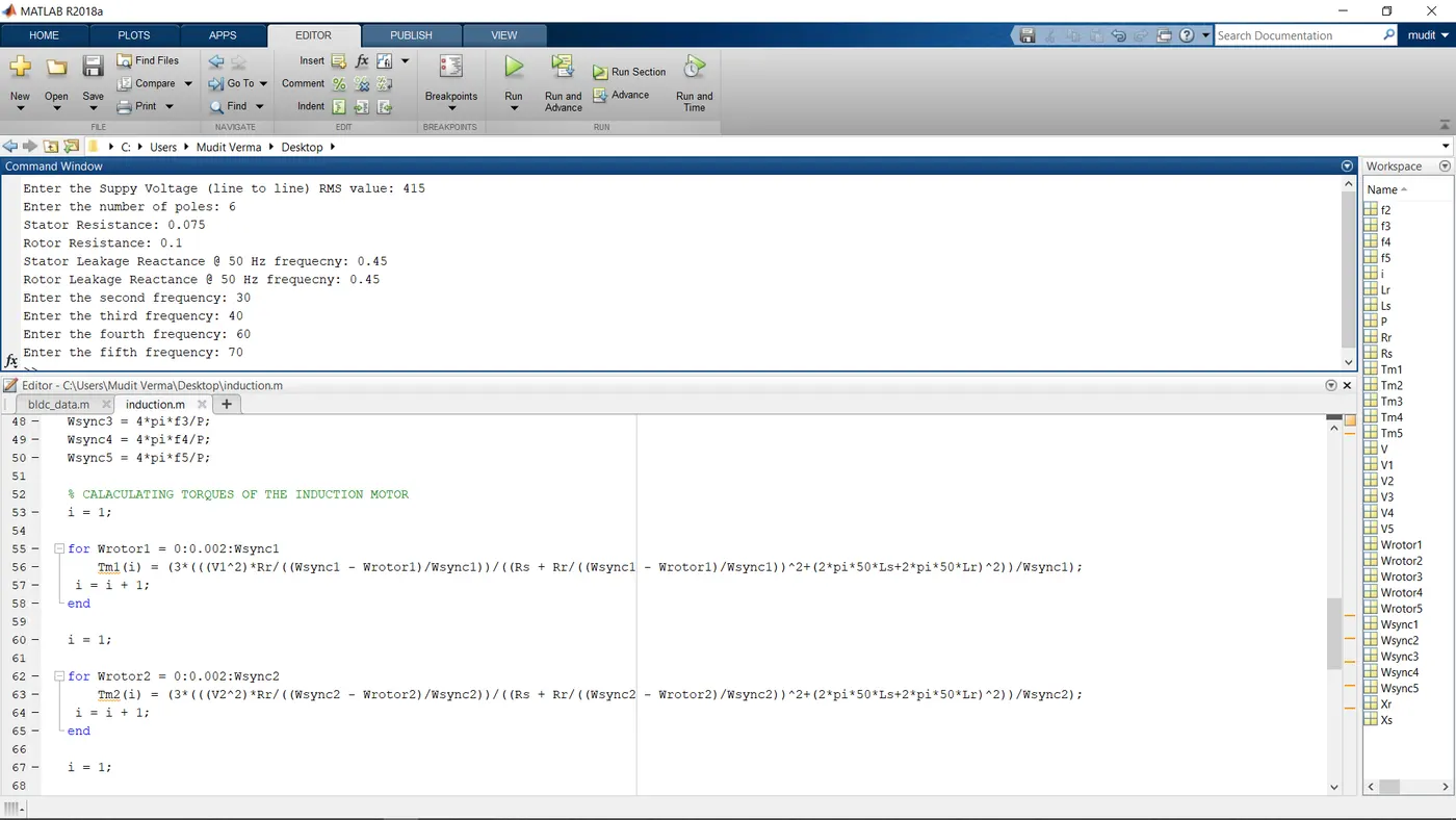
RESULT: -
Torque-Speed Characteristics of 3-phase Induction motor using variable the supply frequency such that the ratio V/f remains constant:-
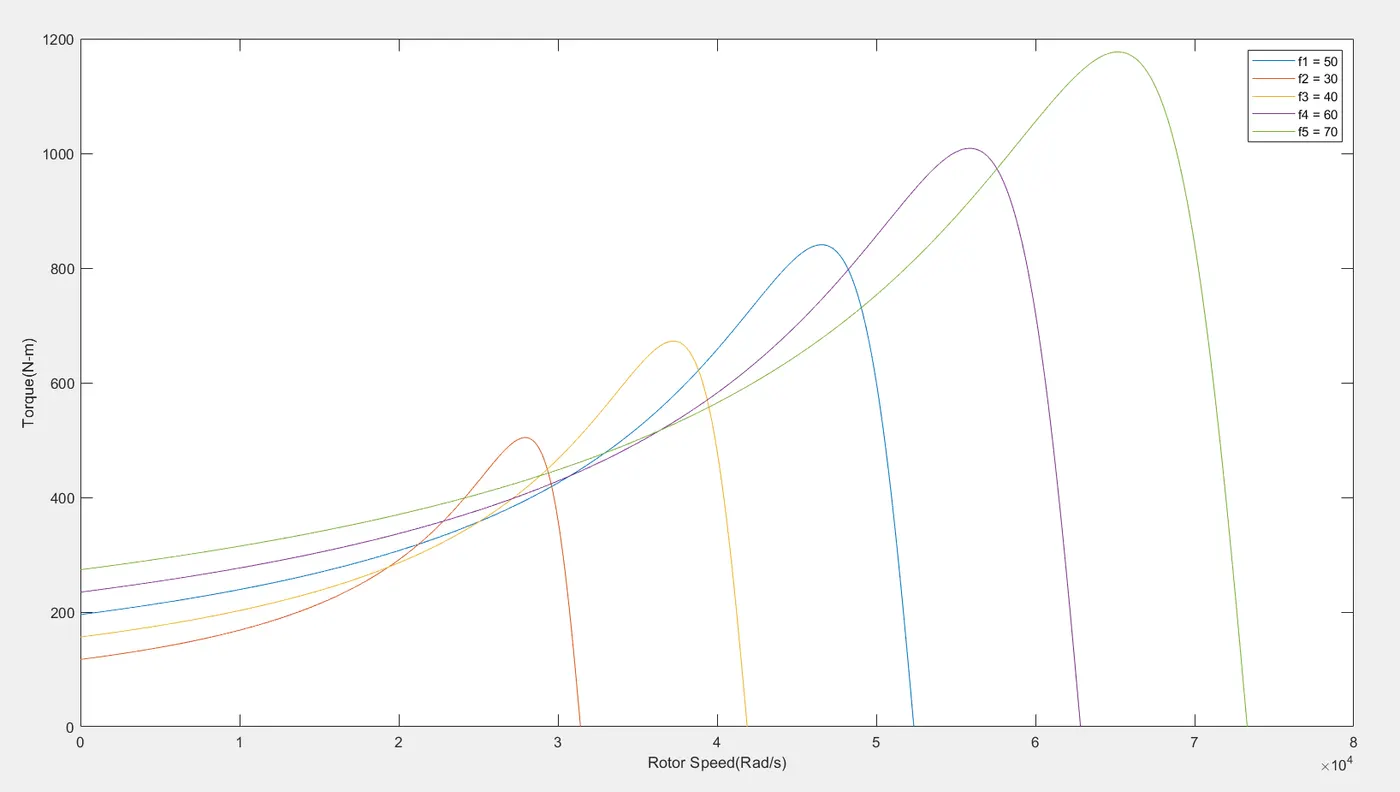
The AC supply is rectified and then applied to a PWM inverter to obtain a variable frequency, variable magnitude 3-phase AC supply. The electromagnetic torque developed by the motor is directly proportional to the magnetic field produced by the stator and the flux produced by the stator is proportional to the ratio of applied voltage and frequency of supply. Therefore, by varying the voltage and frequency by the same ratio, flux and hence, the torque can be kept constant throughout the speed range. This makes constant V/f method the most common speed control method of an induction motor.