Study about the DC Machine and Analyse Torque-Speed Characteristics of DC Motor and Comparison of different types of Electric Motors used in EV.
AIM: - Study about the DC Machine and Analyse Torque-Speed Characteristics of DC Motor and also study about the different types of Electric Motors used in EV.
OBJECTIVE: -
- Detailed Study about the working, principe and construction of DC Machine.
- Analyse and Simulate the Torque-Speed Characteristics of DC Motor.
- Study about the Different types of Electric Motor used in Electric Vehicles and Compare their performance.
SOFTWARE USED: - MATLAB/OCTAVE/ALTAIR COMPOSE and SIMULINK
DC MACHINE: -
The DC machine can be classified into two types namely DC motors as well as DC generators. Most of the DC machines are equivalent to AC machines because they include AC currents as well as AC voltages in them. The output of the DC machine is DC output because they convert AC voltage to DC voltage. The conversion of this mechanism is known as the commutator, thus these machines are also named as commutating machines. DC machine is most frequently used for a motor. The main benefits of this machine include torque regulation as well as easy speed. The applications of the DC machine is limited to trains, mills, and mines. As examples, underground subway cars, as well as trolleys, may utilize DC motors. In the past, automobiles were designed with DC dynamos for charging their batteries.
Working-
A DC machine is an electromechanical energy alteration device. The working principle of a DC machine is when electric current flows through a coil within a magnetic field, and then the magnetic force generates a torque which rotates the dc motor. The DC machines are classified into two types such as DC generator as well as DC motor. The main function of the DC generator is to convert mechanical power to DC electrical power, whereas a DC motor converts DC power to mechanical power. The AC motor is frequently used in the industrial applications for altering electrical energy to mechanical energy. However, a DC motor is applicable where the good speed regulation & ample range of speeds are necessary like in electric-transaction systems.
Construction-
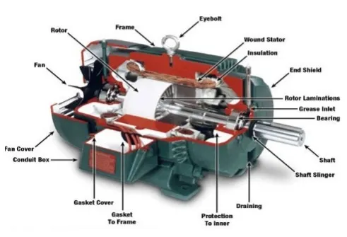
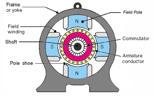
The construction of DC machine can be done using some of the essential parts like Yoke, Pole core & pole shoes, Pole coil & field coil, Armature core, Armature winding otherwise conductor, commutator, brushes & bearings. Some of the parts of the DC machine is discussed below.
Yoke
Another name of a yoke is the frame. The main function of the yoke in the machine is to offer mechanical support intended for poles and protects the entire machine from the moisture, dust, etc. The materials used in the yoke are designed with cast iron, cast steel otherwise rolled steel.
Pole and Pole Core
The pole of the DC machine is an electromagnet and the field winding is winding among pole. Whenever field winding is energized then the pole gives magnetic flux. The materials used for this are cast steel, cast iron otherwise pole core. It can be built with the annealed steel laminations for reducing the power drop because of the eddy currents.
Pole Shoe
Pole shoe in DC machine is an extensive part as well as enlarge the region of the pole. Because of this region, flux can be spread out within the air-gap as well as extra flux can be passed through the air space toward armature. The materials used to build pole shoe is cast iron otherwise cast steed, and also used annealed steel lamination to reduce the loss of power because of eddy currents.
Field Windings
In this, the windings are wounded in the region of pole core & named as field coil. Whenever current is supplied through field winding then it electromagnetics the poles which generate required flux. The material used for field windings is copper.
Armature Core
Armature core includes the huge number of slots within its edge. Armature conductor is located in these slots. It provides the low-reluctance path toward the flux generated with field winding. The materials used in this core are permeability low-reluctance materials like iron otherwise cast. The lamination is used to decrease the loss because of the eddy current.
Armature Winding
The armature winding can be formed by interconnecting the armature conductor. Whenever an armature winding is turned with the help of prime mover then the voltage, as well as magnetic flux, gets induced within it. This winding is allied to an exterior circuit. The materials used for this winding are conducting material like copper.
Commutator
The main function of the commutator in the DC machine is to collect the current from the armature conductor as well as supplies the current to the load using brushes. And also provides uni-directional torque for DC-motor. The commutator can be built with a huge number of segments in the edge form of hard drawn copper. The Segments in the commutator are protected from thin mica layer.
Brushes
Brushes in the DC machine gather the current from commutator and supplies it to exterior load. Brushes wear with time to inspect frequently. The materials used in brushes are graphite otherwise carbon which is in rectangular form.
TORQUE-SPEED CHARACTERISTICS OF DC MACHINE: -
Equivalent Circuit of a DC machiine-
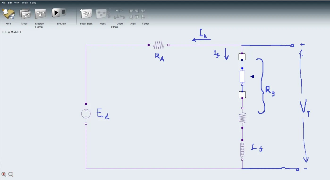
The Output Characteristics of a shunt DC motor can be derived from the induced voltage and torque equations of the motor plus Kirchoff's Voltage Law(KVL),
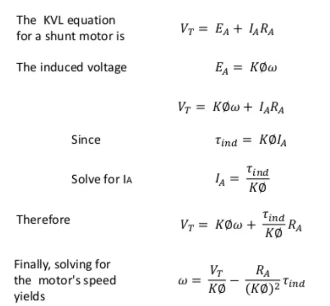
From above equation we get,
The Equation of DC Motor characteristics is,
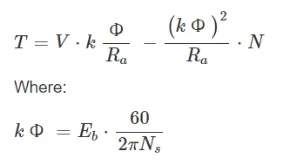
T = Torque (N.m)
V = Voltage Supply (V)
ko = Constant of Proportionality
R_a = Armature Resistance (Ohm)
N = Motor Speed (rad/s)
N_s = Speed constant of a motor
E_b = Back EMF
Implementation of Torque-speed Characteristics equation in Matlab: -
CODE-
clear all
close all
clc

%TORQUE-SPEED CHARACTERISTICS OF DC MACHINE

%Motor Speed Array (rad/s)
N = linspace(0,1500,50);

%Input the Speed constantof a motor
N_s = input('Enter the value of the Speed contant of the motor (rpm): - ');

%Input the Battery Voltage supply
V = input('Enter the value of the Voltage Supply (V): - ');

%Input the Armature Resistance
R_a = input('Enter the value of the Armature Resistance (Ohm): - ');

%Back EMF (It is Directly proportional to motor speed)
E_b = 2;

%Calculating the constant of proportionality
k_phi = (E_b*60)/(N_s*2*3.14);

% Calaculating DC motor Torque-Speed Characteristics using above calculated equation,
T = ((V*k_phi/R_a) - (((k_phi)^2/R_a).*N));

% Speed values in rpm from rad/s
N = N*60/(2*3.14);

%PLOTTING TORQUE-SPEED CHARACTERISTICS
plot(N,T,'b','linewidth',2)
xlabel('Speed of motor (rpm)')
ylabel('Torque of Motor (N.m)')
title('TORQUE-SPEED CHARACTERISTICS OF DC MOTOR')
Explanation of CODE: -
- Firstly, an array of 50 values is taken in account by using linspace command.
- Now, input command to be used so that matlab will ask the inputing value of a desired value.
- Then we will input the the Back EMF value as Back EMF is directly proportional to the motor Speed.
- Then we will calculate the Constant of Proportionality by using the above mentioned formula
- Then we will calculate the Torque-Speed Characteristics of DC motor using Torque Equation as mentioned above.
- Now we will convert the Motor speed values into rpm from rad/s
- Finally, we will Plot the Torque-Speed Characteristics of DC motor and Analyse the Results.
- Now we Run the Simulaton.
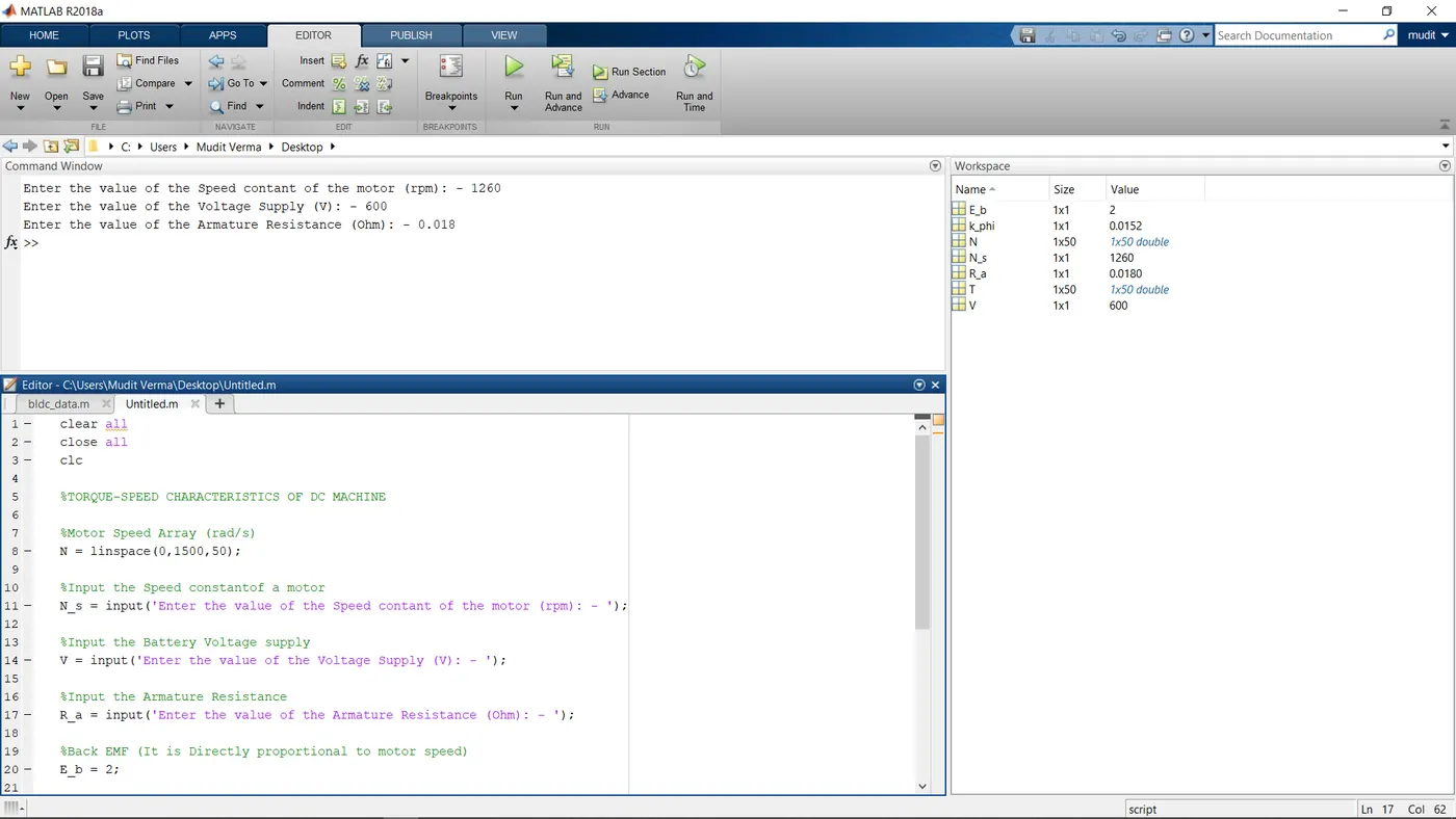
Now, we will input the desired values as asked by the program,
RESULT: -
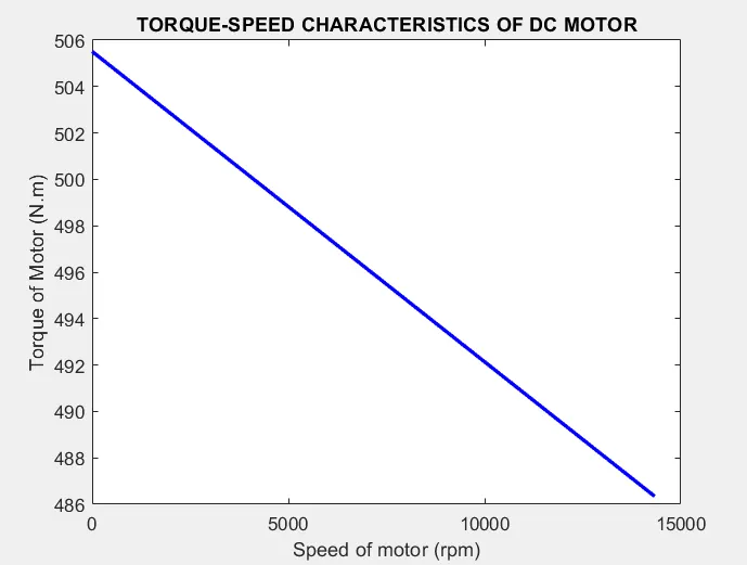
We can observe that Torque (Nm) of the DC motor is inversely proportional to the Speed of the motor (rpm) as the Speed of motor increases the Torque of the DC motor decreases approximately linearly. So the manufacturer of Electric vehicle domain can easily design an DC motor for desired purpose example with more speed and less Torque designed motor for less powered vehicles.
DIFFERENT TYPES OF ELECTRIC MOTORS USED IN ELECTRIC VEHICLES: -
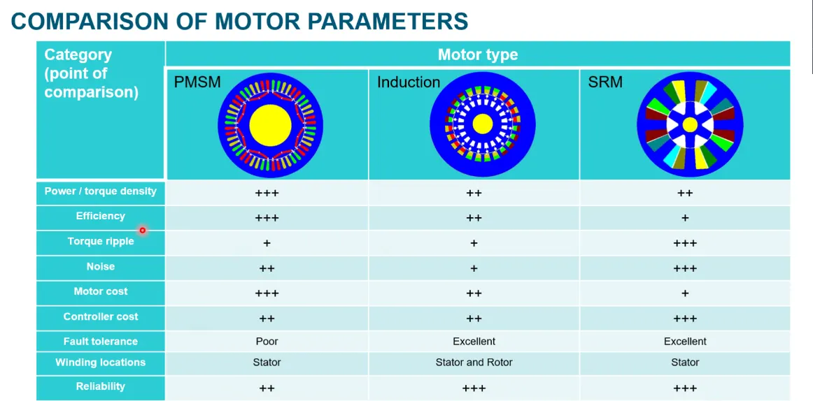
Brushless DC Motor (PMSM)-
This motor has a stator and a rotor with an electric coil in it. When this coil is connected with the battery, producing a direct current, the coil produces a magnetic field which causes the rotor to rotate to have the poles face the opposite poles of the permanent magnets in the stator. To keep this momentum, the polarity of the coils is switched.
Before explaining the working of a brushless DC motor, it is better to understand the function of a brushed motor. In brushes motors, there are permanent magnets on the outside and a spinning armature which contains electromagnet is inside. These electromagnets create a magnetic field in the armature when the power is switched on and help to rotate the armature.The brushes change the polarity of the pole to keep the rotation on of the armature. The basic working principle for the brushed DC motor and for brushless DC motor are same i.e. internal shaft position feedback.Brushless DC motor has only two basic parts: rotor and the stator. The rotor is the rotating part and has rotor magnets whereas stator is the stationary part and contains stator windings. In BLDC permanent magnets are attached in the rotor and move the electromagnets to the stator. The high power transistors are used to activate electromagnets for the shaft turns. The controller performs power distribution by using a solid-state circuit.
Advantages-
- Brushless motors are more efficient as its velocity is determined by the frequency at which current is supplied, not the voltage.
- As brushes are absent, the mechanical energy loss due to friction is less which enhanced efficiency.
- BLDC motor can operate at high-speed under any condition.
- There is no sparking and much less noise during operation.
- More electromagnets could be used on the stator for more precise control.
- BLDC motors accelerate and decelerate easily as they are having low rotor inertia.
- It is high performance motor that provides large torque per cubic inch over a vast sped rang.
- BLDC motors do not have brushes which make it more reliable, high life expectancies, and maintenance free operation.
Disadvantage-
- BLDC motor cost more than a brushed DC motor.
- The limited high power could be supplied to BLDC motor, otherwise, too much heat weakens the magnets and the insulation of winding may get damaged.
Induction Motor-
The AC induction motor needs no permanent magnets. Instead the magnetic field is produced by a current that flows through the windings in the housing or stator. Now if you connect the stator to an alternating current, this means the magnetic field in the stator will also alternate. If a three phase AC input is used, a so called rotating magnetic field or RMF is produced. The magnetic field from the stator will induce a voltage and current in the windings of the rotor. That’s why it’s called the induction motor. This in turn leads to the rotor producing its own magnetic field, and this magnetic field will make the rotor turn so as to align itself with the magnetic field from the stator. The rotor will follow this rotating magnetic field in the stator, without the need for a commutator with brushes.
The most important advantage of an induction motor is that its construction is quite simple in nature. The construction of the Stator is similar in both Synchronous motors as well as induction motors. However, a slip ring is required to feed DC Supply to the Rotor in the case of a Synchronous Generator. These Slip rings are not required in a Squirrel cage induction motor because the windings are permanently short circuited. When compared with a DC Motor, the induction motor does not have Brushes and hence, maintenance required is quite low. This leads to a simple construction.
Advantages-
- The working of the motor is independent of the environmental condition. This is because the induction motor is Robust and mechanically strong.
- A Squirrel cage induction motor does not contain Brushes, Slip rings and Commutators. Due to this reason, the cost of the motor is quite low. However, Slip Rings are used in Wound type induction motor to add external resistance to the rotor winding.
- Due to the absence of Brushes, there are no sparks in the motor. It can also be operated in hazardous conditions.
- Unlike synchronous motors, a 3 phase induction motor has a high starting torque, good speed regulation and reasonable overload capacity.
- An induction motor is a highly efficient machine with full load efficiency varying from 85 to 97 percent.
Disadvantage-
- Speed control of an induction motor is very difficult to attain. This is because a 3 phase induction motor is a constant speed motor and for the entire loading range, the change in speed of the motor is very low.
- Induction motors have high input surge currents, which are referred to as Magnetising Inrush currents. This causes a reduction in voltage at the time of starting the motor.
- Due to poor starting torque, the motor cannot be used for applications which require high starting torque.
- During light load conditions, the power factor of the motor drops to a very low value. This is because during the start, the motor draws a large magnetising current to overcome the reluctance offered by the air gap between the Stator and the Rotor.
Synchronous Reluctance Motor-
The synchronous reluctance motor has only recently been developed and seems to have best of both worlds. It has a rotor that contains metal that is formed in such a way that it wants to align itself naturally to the surrounding magnetic field. This means it doesn’t need to produce its own electric field through induced currents, like the induction motor, whicht means less losses. Finally, it doesn’t need permanent magnets which makes it much cheaper than a permanent magnet motor.
The alternating current passing through the stator windings creates a rotating magnetic field in the air gap of the electric motor. Torque is created when the rotor attempts to establish its most magnetically conductive axis (d-axis) with an applied field in order to minimize the reluctance (magnetic resistance) in the magnetic circuit. The amplitude of the torque is directly proportional to the difference between the direct Ld and quadrature Lq inductances. Therefore, the greater the difference, the greater the torque created.
Advantages-- Simple and robust rotor construction:- The rotor has a simple structure consisting of sheet electrical steel, without magnets and short-circuited winding.
- Low heat:- Since there are no currents in the rotor, it does not heat up during operation, increasing the service life of the electric motor.
- No magnets:- The final price of the electric motor is reduced since rare earth metals are not used in production. In the absence of magnetic forces, the maintenance of the electric motor is simplified.
- Low moment of inertia of the rotor:- Since there is no winding and magnets on the rotor, the moment of inertia of the rotor is lower, which allows the electric motor to accelerate faster and save energy.
- Speed control:- In view of the fact that synchronous reluctance motor for its operation requires a frequency converter, it is possible to control the speed of rotation of reluctance motor in a wide range of speeds.
- Frequency control:- To work requires a variable frequency drive.
- Low power factor:- Due to the fact that the magnetic flux is generated only by the reactive current. Solved by the use of a variable frequency drive with power correction.
COMPARISON OF ELECTRIC MOTORS USED IN EV: -