Analysis and Simulation of the 3D created Centrifugal pump and obtain relationship between Pressure ratio and mass flow rate
OBJECTIVE :-
Analysis and Simulation of the 3D created Centrifugal pump and obtain relationship between Pressure ratio and mass flow rate.
COMPUTATIONAL FLUID DYNAMICS (CFD) :-
Computational fluid dynamics (CFD) is a branch of fluid mechanics that uses numerical analysis and data structures to analyze and solve problems that involve fluid flows. Computers are used to perform the calculations required to simulate the free-stream flow of the fluid, and the interaction of the fluid (liquids and gases) with surfaces defined by boundary conditions. With high-speed supercomputers, better solutions can be achieved, and are often required to solve the largest and most complex problems. Ongoing research yields software that improves the accuracy and speed of complex simulation scenarios such as transonic or turbulent flows. Initial validation of such software is typically performed using experimental apparatus such as wind tunnels. In addition, previously performed analytical or empirical analysis of a particular problem can be used for comparison. A final validation is often performed using full-scale testing, such as flight tests.
CFD is applied to a wide range of research and engineering problems in many fields of study and industries, including aerodynamics and aerospace analysis, weather simulation, natural science and environmental engineering, industrial system design and analysis, biological engineering, fluid flows and heat transfer, and engine and combustion analysis.
Methodology:-
In all of these approaches the same basic procedure is followed.
During preprocessing
- The geometry and physical bounds of the problem can be defined using computer aided design (CAD). From there, data can be suitably processed (cleaned-up) and the fluid volume (or fluid domain) is extracted.
- The volume occupied by the fluid is divided into discrete cells (the mesh). The mesh may be uniform or non-uniform, structured or unstructured, consisting of a combination of hexahedral, tetrahedral, prismatic, pyramidal or polyhedral elements.
- The physical modeling is defined – for example, the equations of fluid motion + enthalpy + radiation + species conservation
- Boundary conditions are defined. This involves specifying the fluid behaviour and properties at all bounding surfaces of the fluid domain. For transient problems, the initial conditions are also defined.
- The simulation is started and the equations are solved iteratively as a steady-state or transient.
- Finally a postprocessor is used for the analysis and visualization of the resulting solution.
CENTRIFUGAL PUMP :-
Centrifugal pumps are used to transport fluids by the conversion of rotational kinetic energy to the hydrodynamic energy of the fluid flow. The rotational energy typically comes from an engine or electric motor. They are a sub-class of dynamic axisymmetric work-absorbing turbomachinery.[1] The fluid enters the pump impeller along or near to the rotating axis and is accelerated by the impeller, flowing radially outward into a diffuser or volute chamber (casing), from which it exits.
Common uses include water, sewage, agriculture, petroleum and petrochemical pumping. Centrifugal pumps are often chosen for their high flow rate capabilities, abrasive solution compatibility, mixing potential, as well as their relatively simple engineering.[2] A centrifugal fan is commonly used to implement a vacuum cleaner. The reverse function of the centrifugal pump is a water turbine converting potential energy of water pressure into mechanical rotational energy.
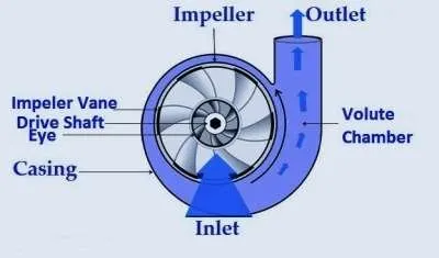
Main Parts of Centrifugal Pump
1. Impeller-
It is a wheel or rotor which is provided with a series of backward curved blades or vanes. It is mounded on the shaft which is coupled to an external source of energy which imparts the liquid energy to the impeller there by making it to rotate.
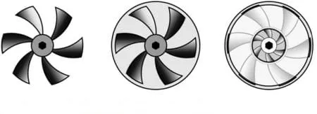
Fig 2: Open, Semi Enclosed and Enclosed Impeller.
Impellers are divided into 3 types,
- Open Impeller
- Semi enclosed Impeller
- Enclosed Impeller
2. Casing-
It is a pipe which is connected at the upper end to the inlet of the pump to the centre of impeller which is commonly known as eye. The double end reaction pump consists of two suction pipe connected to the eye from both sides. The lower end dips into liquid in to lift. The lower end is fitted in to foot valve and strainer.
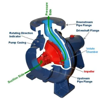
Fig 3: Main Components of Centrifugal Pump.
Commonly three types of casing are used in centrifugal pump,
- Volute Casing
- Vortex Casing
- Casing with Guide Blades
3. Delivery Pipe-
It is a pipe which is connected at its lower end to the out let of the pump and it delivers the liquid to the required height. Near the outlet of the pump on the delivery pipe, a valve is provided which controls the flow from the pump into delivery pipe.
4. Suction Pipe with Foot Valve and Strainer-
suction pipe is connected with the inlet of the impeller and the other end is dipped into the sump of water. At the water end, it consists of foot value and strainer. The foot valve is a one way valve that opens in the upward direction. The strainer is used to filter the unwanted particle present in the water to prevent the centrifugal pump from blockage.
Working of Centrifugal Pump:-
The first step in the operation of a centrifugal pump is priming. Priming is the operation in which suction pipe casing of the pump and the position of fluid with the liquid which is to be pumped so that all the air from the position of pump is driven out and no air is left. The necessity of priming of a centrifugal pump is due to the fact that the pressure generated at the centrifugal pump impeller is directly proportional to density of fluid that is in contact with it.
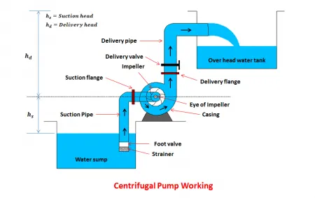
Fig 4: Working of Centrifugal Pump.
After the pump is primed the delivery valve is still kept closed and electric motor is started to rotate the impeller. The delivery valve is kept closed in order to reduce valve is opened the liquid is made to flow in an outward radial direction there by vanes of impeller at the outer circumference with high velocity at outer circumference due to centrifugal action vacuum is created.
This cause liquid from sump to rush through suction pipe to eye of impeller thereby replacing long discharge from center circumference of the impeller is utilized in lifting liquid to required height through delivery pipe.
Types of Centrifugal Pumps:-
Centrifugal Pumps are classified into many types based on many categories, they are
Based on number of impellers in the pump,
- Single stage pump
- Two-stage pump
- Multi-stage pump
Based on orientation of case-split,
- Axial split Pump
- Radial split Pump
Based on type of impeller design,
- Single suction Pump
- Double suction Pump
Based on the basis compliance with industry standards,
- ANSI pump – (American National Standards Institute)
- API pump – (American Petroleum Institute)
- DIN pump – DIN 24256 specifications
- ISO pump – ISO 2858, 5199 specifications
- Nuclear pump – ASME (American Society of Mechanical Engineers) specifications
Based on type of volute
- Single volute Pump
- Double volute Pump
Based on where the bearing support is,
- Overhung
- Between-bearing
Based on on shaft orientation
- Horizontal Pump
- Vertical Pump
Application of Centrifugal Pumps:-
- Oil & Energy – pumping crude oil, slurry, mud; used by refineries, power generation plants
- Industrial & Fire Protection Industry – Heating and ventilation, boiler feed applications, air conditioning, pressure boosting, fire protection sprinkler systems.
- Waste Management, Agriculture & Manufacturing – Wastewater processing plants, municipal industry, drainage, gas processing, irrigation, and flood protection
- Pharmaceutical, Chemical & Food Industries – paints, hydrocarbons, petro-chemical, cellulose, sugar refining, food and beverage production
- Various industries (Manufacturing, Industrial, Chemicals, Pharmaceutical, Food Production, Aerospace etc.) – for the purposes of cryogenics and refrigerants.
---------------------------------------------------------------------------------------------------------------------
PROCEDURE :-
- Firstly create an Impeller using just eye balling the parameters and create 6 blades by using circular pattern.
- Then extrude the open Impeller to 40mm.
- Enclose the Impeller by the 90mm cylinder and then extrude it and keep in mind the to uncheck the marge the results.
- Now perform casting by creating suction pipe of radius 20mm and extrude it to 70mm.
- Create an outlet pipe by using sweep features by using reference plane.
- Uncheck merge results and combine all parts using boolean expression.
- Create transperency in the parts.
- Now, Create an Rotating Chamber covering the Impeller and covered by the enclosed chamber.
- Now create shell at in all parts of the centrifugal pump of 2mm.
Geometry-
BASE LINE SIMULATION:-
- Go to Flow Simulation.
- Create Lids at both the face of the suction pipe and outlet pipe.
- Create wizard and apply general settings.
- Go to default unit system
- Internal Anlysis is applied and Select Rotation with local region averaging.
- Working fluid -> Water with Laminar and turbulent flow.
- Go with default wall conditions, thermodynamics condition.
- Input data -> Component control -> Exclude the Model of the moving reference over the Impeller.
- Rotation zone -> Add the Model of the moving reference over the Impeller -> angular velocity 1000rad/s.
- Add Boundry condition
- @ Inlet face -> Envirnomental Pressure
- @ Outlet face -> Outlet velocity of 10 m/s
- Add mesh and use Advanced channel refinement
- Add Goals
- Surface Goal -> Average Total Pressure @ Outlet Lid
- Surface Goal -> Average Total Pressure @ Inlet Lid
- Surface Goal -> Mass Flow Rate @ Outlet Lid
- To avoid solution converge quickly,
- Click on input data -> Calculation Control Options -> Enable only Iterations = 500
- Run the Simulation and Analyse the result.
Simulation Results :-
Velocity Plot-
Velocity Flow-
Pressure Plot-
Pressure Flow-
Velocity Flow Animation-
Pressure Flow Animation-
PARAMETRIC STUDY :-
With the same above simulation input parameter, Setup an Parametric study.
- Input Variables
- Boundary Conditions -> Outlet Velocity on outlet pipe -> Discrete values from 10m/s to 30m/s with 5 design point
- Output Variables
- Add Goals -> Average Total Pressure and Mass Flow Rate
- Add Results -> Cut Plots and Flow Trajectories
- Run the Simulation
Results :-
Goals:-
Outlet Pressure-
Inlet Pressure-
Mass Flow Rate-
## Mass Flow Rate is Negative because liquid is coming out of the centrifugal pump so negative sign is considered but we will consider only magnitude for our calculation purpose.
%Now,

%Pressure Ratio = Outlet pressure/Inlet pressure

T%otal 5 Design Points

P1 = 1791554.66/121919.23 = 14.69

P2 = 3067378.12/340114.78 = 9.01

P3 = 6575501.42/707118.94 = 9.29

P4 = 2183719.26/216122.47 = 10.1

P5 = 3311620.33/410790.28 = 8.06
There is the relatively Decrease in the Pressure as decrease in the Outlet Pressure due to increase in the Outlet Velocity which thereby increases Pressure Drop.
Cut and Flow Plots at 10m/s :-
Velocity Plot-
Velocity Flow-
Pressure Plot-
Pressure Flow-
Cut and Flow Plots at 15m/s :-
Velocity Plot-
Velocity Flow-
Pressure Plot-
Pressure Flow-
Cut and Flow Plots at 20m/s :-
Velocity Plot-
Velocity Flow-
Pressure Plot-
Pressure Flow-
Cut and Flow Plots at 25m/s :-
Velocity Plot-
Velocity Flow-
Pressure Plot-
Pressure Flow-
Cut and Flow Plots at 30m/s :-
Velocity Plot-
Velocity Flow-
Pressure Plot-
Pressure Flow-
CONCLUSION :-
% PRESSURE RATIO VS MASS FLOW RATE OF CENTRIFUGAL PUMP

% Input

%Pressure ratio
P_r = [14.69 9.01 9.29 8.1 8.06];

%Mass Flow Rate[kg/s]
m_f_s = [0.4953 0.7383 0.9540 1.2339 1.4815];

%Plotting
plot(m_f_s, P_r,'o-')
xlabel('Mass Flow Rate[kg/s]')
ylabel('Pressure Ratio')
title('PRESSURE RATIO VS MASS FLOW RATE OF CENTRIFUGAL PUMP')
Approximately, There is increase in the Mass Flow Rate with the Increase in Pressure Ratio in Centrifugal Pump.