Simulation of Forward Kinematics of 2R Robotic arm
AIM: To write a program in MATLAB to simulate the forward kinematics of a 2R Robotic Arm.
OBJECTIVE:
- The main objective is to first generate Matlab program for a 2R Robotic arm while explaining step by step coding and showcase the errors which come across with description and solution how to resolve it.
- Create an animation file of the final result of simulation of 2R Robotic Arm and upload in YouTube channel.
- Should provide the uploaded animation file link in the project page description.
GOVERNING EQUATION:
Kinematics: It is the study of theory of machines which deals with the relative motion between the various parts of machine without considering the cause of motion or forces.
Each part of a machine which moves relative to other part is known as Kinematic link.
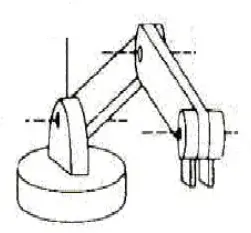
2R Robotic arm means two links rotation about an axis perpendicular to the adjoining links. Here the length of the adjoining links do not change but relative position of the links with respect to the one another changes as rotation takes place.
In robot motion analysis, we study the geometry of arm with respect to a reference co-ordinate system, while the end effector moves along the prescribed path.
BODY CONTENT:
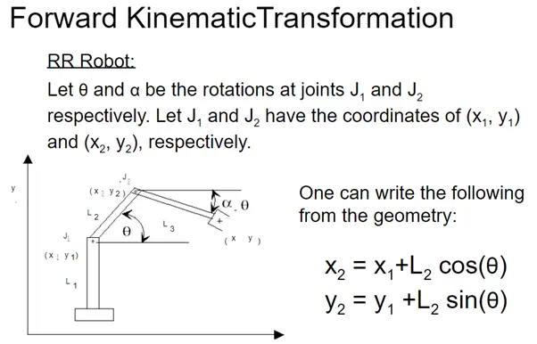
For simulation of forward Kinematics of 2R Robotic Arm, we have taken two links or arms of length and. The links and have an inclination of angles theta1 and theta2 with x-axis. The positions of the ends of the links are taken as (`x0,y0`), ( `x1,y1`) and (`x2,y2`)
Step1: calculate the position of link1 and link2.
One end of link 1 is pivoted to the base at (`x0,y0`) and the other end is taken as ( `x1,y1`). Since the link1 makes an angle of theta1 with the base, using Pythagoras theorem we get
`x1=l1astcosd(the ta1)`
`y1=l1astsind(the ta2)`
One end of link2 is joined to the end of link1, it takes the same position of (`x1,y1)` The other end of link2 is to be calculated as follow
`x2=x1+l1astcosd(the ta2)`
`y2=y1+l1astsind(the ta2)`
In workspace we can see the positions of (`x1,y1` ) and (`x2,y2`) with respect to origin (`x0,y0`)
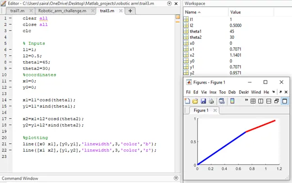
The above frame displays the robotic arms with single position. Now our aim is to animate both the arms with some angles for few seconds. For that we use ‘for loop’ and recode the program. Let us see.
Step2:
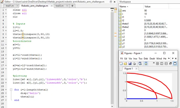
Using ‘linspace’ command we have taken the angles for both the arms and links from 0 to 90 degree angles with length 10. It means link2 takes ten positions for each position of link1. We need to use the ‘for-loop’ to iterate 10 positions of each link.
Step3: By using For-Loop, iteration of position of links takes place within specified length.
ERROR1:
While running for-Loop I am getting an error as shown below. This is because here I have assigned coordinates and Line command outside the for-loop.
Using for-loop, only the link2 has taken the 10 angles for 10 positions of link1 which are assigned to variable `i=1: l e n g th(the ta1)` ,`the ta2(i)` but not the link1 and showed the plot. So we need another for-loop to assign the values of positions of link2 in another variable ‘j’.
Now we removed line command and co-ordinates and given inside for-loop.
ERROR2:
Again error occurred as shown below
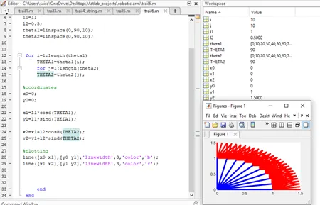
to resolve this, contour command is used.
`ct=1;`
`ct=ct+1;`
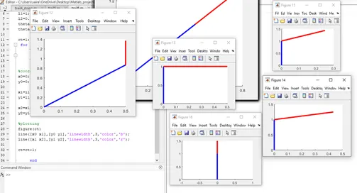
Results were displayed in different frames. If length is 10 means 100 frames will be generated.
Now we can use figure () command to display number of frames in one window.
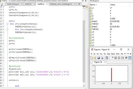
ERROR3:
Changing command from line to plot we get 16 frames if length is 4 displaying only the second link i.e. link2. This is because plot command takes the last value of THETA2 by overwriting the previous values THETA1. Here the link1 position values. By giving hold on command, we can remove the error.
Error4:
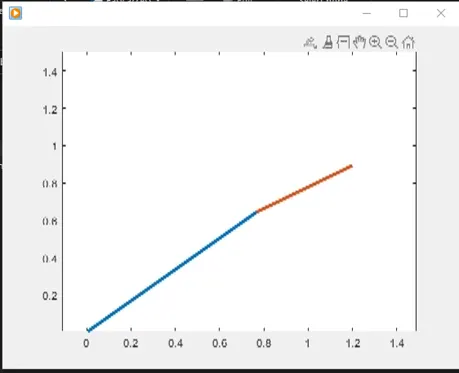
Here instead of giving figure (ct), I have written figure (2). Code executed an animated file as shown below.
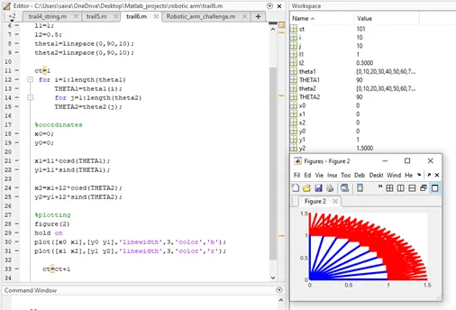
By removing figure () command and hold on command, code is executed in single frame.
By giving axis command we can fix the X-axis and Y-axis limits. Each frame is taken in an array M () by using getframe command and input value is taken gcf which is the plot name.
Movie command is written to get animated file of robotic arm
Final Code:
clear all
close all
clc


% Inputs
l1=1;
l2=0.5;
theta1=linspace(0,90,10);
theta2=linspace(0,90,10);
ct=1;
for i=1:length(theta1)
THETA1=theta1(i);
for j=1:length(theta2)
THETA2=theta2(j);

%coordinates
x0=0;
y0=0;

x1=l1*cosd(THETA1);
y1=l1*sind(THETA1);

x2=x1+l2*cosd(THETA2);
y2=y1+l2*sind(THETA2);

%plotting
 plot([x0 x1],[y0 y1],[x1,x2],[y1,y2],'linewidth',3);
axis([-0.1 1.5 0 1.5])
pause(0.03)
M(ct)=getframe(gcf);
ct=ct+1;

end
end

movie(M)
videofile=VideoWriter('Forward_Kinematics.avi','uncompressed AVI');
open(videofile)
writeVideo(videofile,M)
close(videofile)
Animated File:
Link uploaded in YouTube :
CONCLUSION: Programming the software for robotic arms has greater flexibilty, re-programmability, improve product quality ,accident reduction and so on.The applications of such robotic arms are playing ideal role in loading and unloading of parts to the machines or from the machines done mostly in die-casting , forging,sheet metal blanching , injection molding , NC machine tools operations. They also uses in welding, sparying, assembly also.