Section Modulus calculation and optimization
SECTION MODULUS CALCULATION AND OPTIMIZATION
OBJECTIVE :
Use the Section from your Hood design and calculate the Section Modulus using the formula
S = I/y
SECTION MODULUS :
Section modulus is a geometric property for a given cross-section used in the design of beams or flexural members. It is a direct measure of the strength of the beam. A beam that has a larger section modulus than another will be stronger and capable of supporting greater loads.
It includes the idea that most of the work in bending is being done by the extreme fibres of the beam, ie the top and bottom fibres of the section. The distance of the fibres from top to bottom is therefore built into the calculation.
The section modulus is denoted by S. To calculate S, the distance (y) to the extreme fibres from the centroid (or neutral axis) must be found as that is where the maximum stress could cause failure.
S = I / y
where "I" is the area moment of inertia of the section about the bending axis.
AREA MOMENT OF INERTIA (I) :
Area moment of inertia also known as second area moment or 2nd moment of area is a property of a two-dimensional plane shape where it shows how its points are dispersed in an arbitrary axis in the cross-sectional plane. This property basically characterizes the deflection of the plane shape under some load.
Area moment of inertia is usually denoted by the letter I for an axis in a plane. It is also denoted as J when the axis lies perpendicular to the plane. The dimension unit of second area moment is Length to the power of four which is given as L4. If we take the International System of Units, its unit of dimension is meter to the power of four or m4.
BENDING EQUATION : The axial deformation of the beam due to external load that is applied perpendicularly to a longitudinal axis is called the Bending Theory. The Bending equation is,
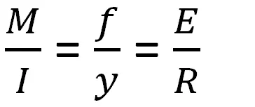
M = Resistive Bending Moment
f = Bending Stress
E = Young's Modulus
R = Radius of curvature of bend
from the equation,
M = ( f * I ) / y
M = f * S
S = M / f, From the equation it's clear that the Section Modulus is proportional to the Resistive Bending Moment. So it depicts that if a body is having greater section modulus, it will show strong resistance towards bending.
In our case, the body is Hood Assembly which I created earlier in the Hood design.
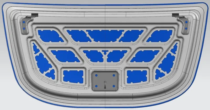
In the below figure shows the cross sectional view of the Hood design. And in this challenge the aim is to find the section modulus of this area.
Case 1 : Before Optimization
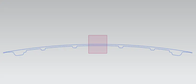
The section modulus of the given area is found as shown below.
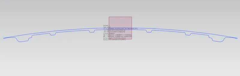
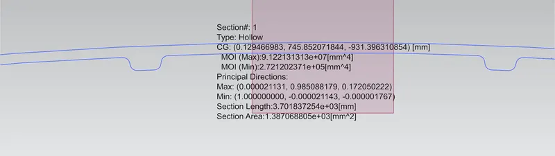
MOI (max) = 9.122131313e+07 (mm^4)
MOI (min) = 2.72120237e+05 (mm^4)
As per the section modulus equation,
S = I / Y
Minimum value of MOI is considered, as the body should withstand under any condition. So if we consider the minimum value of MOI, it will with stand under any condition above that MOI value of that particular section.
Total distance of the section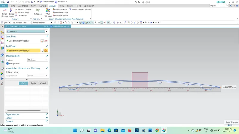
Y = Total distance /2, Total distance =878.6098 mm
Y = 878.6098 / 2
Y = 439.3049 mm
Therefore, S = 272120.237 / 439.3049 mm
= 619.43364 mm^3
Case 2 : After Optimization
Another emboss has been created as shown in the figure
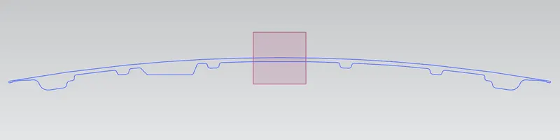
MOI has been found and is increased compared with the initial value
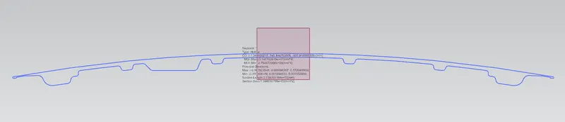
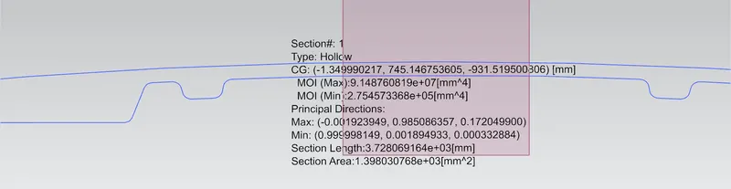
MOI (max) = 9.148760819e+07 (mm^4)
MOI (min) = 2.754573368e+05 (mm^4)
Y = 439.3049 mm
Therefore, S = 275457.3368 / 439.3049 mm
= 627.03 mm^3
CONCLUSION :
- When comparing cases 1 and 2, it is notable that the moment of inertia is rising as the area increases.
- The section modulus of the design increases together with the moment of inertia.
- Therefore, increasing the area enhances the design's strength.