Week 8 - Challenge 2 - Switch Bezel Design
SWITCH BEZEL CHALLENGE 2
AIM :
Create the Switch Bezel Plastic component through the given Class-A surface.
THEORY :
TOOLING AXIS :
Tooling axis is the direction in which the core and cavity opens and closes. In order to construct the Class B and Class C surfaces, it is crucial to determine the tooling axis from a Class A surface since this axis serves as a reference line for the draft angle.
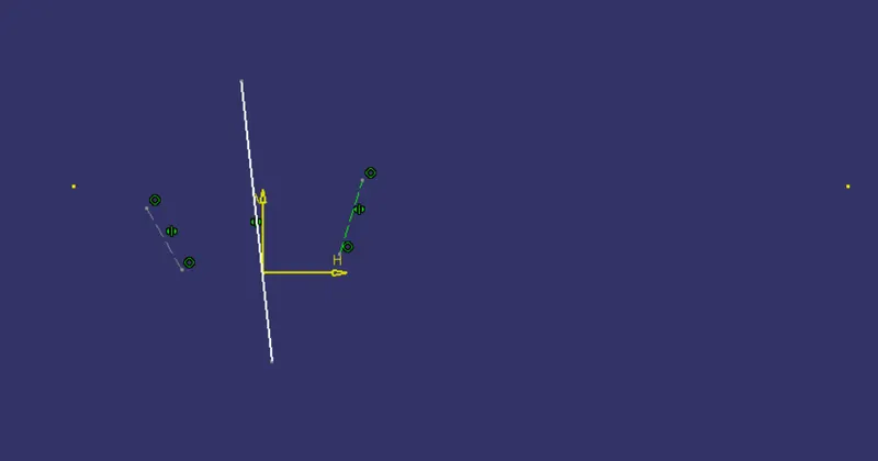
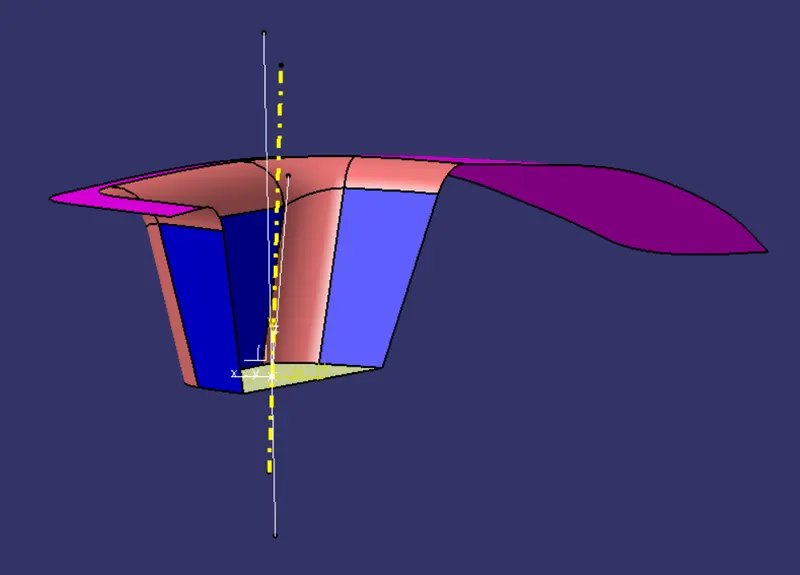
In this challenge, the tooling axis is discovered by creating the two lines shown over the sketch, which are produced via the intersection tool inside Catia, and then bisecting those two lines to obtain the tooling axis in Y direction. The intersection is performed over the provided Class A surface, and the resulting sketch is displayed below.
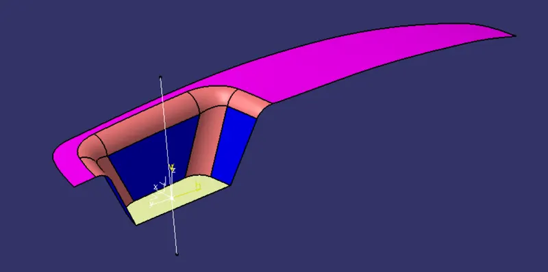
Similarily, the tooling axis in X direction is also found. Just by creating a line 5 degrees apart from the side wall passing through the center point on the bottom surface.
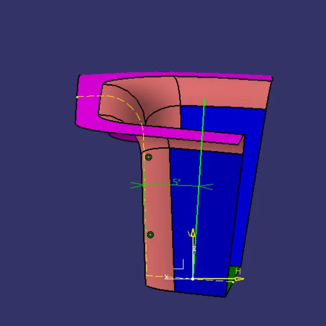
The tooling axis found in X and Y direction is then bisected to produce the main tooling axis.
DRAFT ANALYSIS :
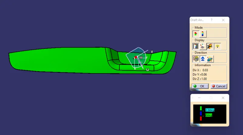
In order to recognise that our drafted component is at an angle that is higher than the typical draft angle, which is about 3 degrees, draft analysis is employed. Draft analysis is done using a tool in Catia called "Feature draft analysis." When you click on this tool, the window below will appear.
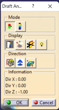
- In the mode section, there are two modes: the Quick analysis mode and the Full analysis mode. In this challenge, quick analysis mode is being used to visualise draft analysis.
- First, a tool named "Compass" from the direction category is used to define new draft direction. The direction of the draft is determined by positioning that compass above the tooling axis.
- Then by just clicking over the surface or the component we can visualize the colour corresponding to the angle as set in the draft analysis.
- There is an another tool which is used to find angles at running points. The tool is under display category, in that by selecting the tool named "Analyses under the running point" there by moving the cursor over the component gives the draft angle at that particular point on the component.
- There is an another tool to change the draft direction of the compass, which is under direction category next to the compass tool.
PROCEDURE :
- First we will find the tooling axis, for that we need to analyse the given component to find the which tooling direction is better to avoid the use of side cores and other complexity. In our case Z-direction is the better tooling direction for better manufacturability.
- The tooling axis is found by bisecting method that already discussed in the theory section.
- After bisecting the main tooling axis is found.
- By Feature draft analysis tool the draft analysis of the class A surface is done initially to know whether our find class A is acceptable or not.
Draft analysis over class A surface
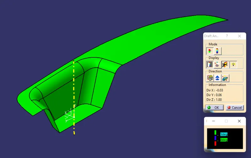
- From the figure it can understand that our given class A is ensuring better draft as the surface is lightened in green representing the angle is greater than or equal to 3 degrees.
- Then nextly creating class B and class C surfaces over the class A by providing necessary thickness of about 2.5 mm. Then my trimming the unnecessary portions to get the each feature and make a closed surface inside partbody.
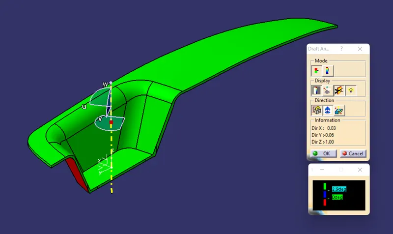
- Then the draft analysis of that particular part body is performed.
Draft analysis of closed surface part body
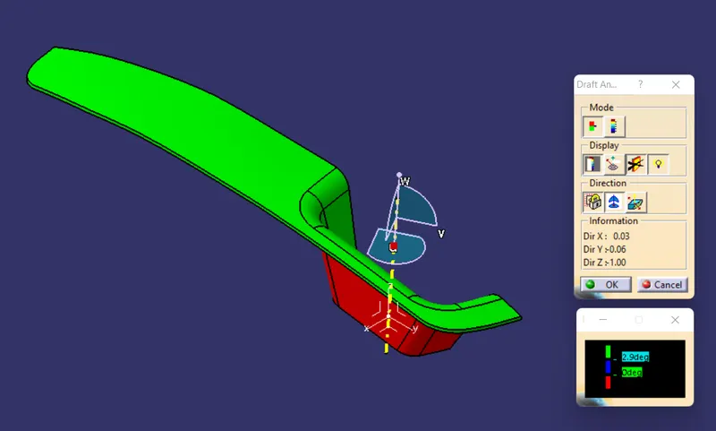
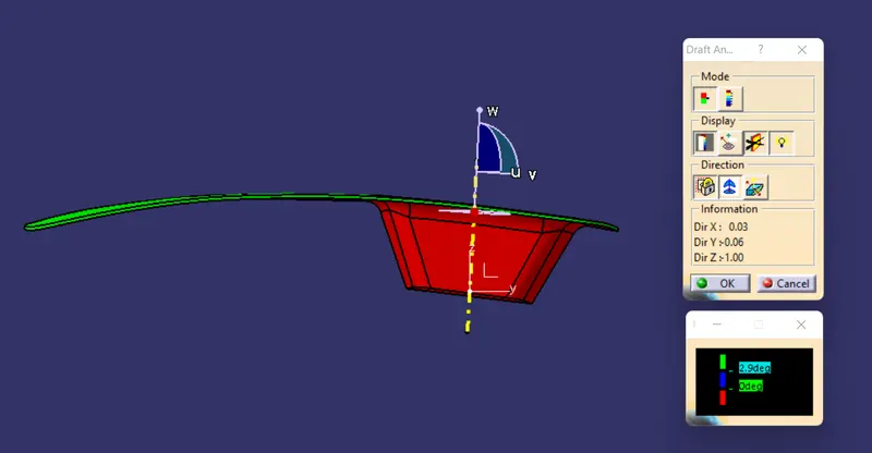
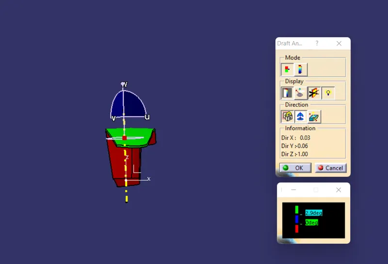
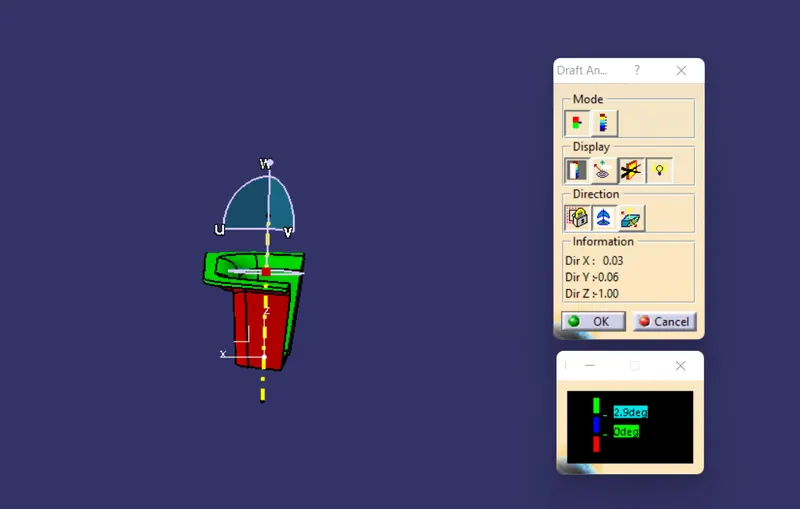
- Draft angle is provided 3 degrees even though some of the areas in class c surface do not achieved 3 degree angle instead around 2.9 degrees is found. So I provided 2.9 degree as the minimum angle for draft (green) as shown. So the class A and class C become green colour.
ISOMETRIC VIEW
FRONT VIEW
LEFT END VIEW
RIGHT END VIEW
TOP VIEW