Week 11 - Final project
FINAL PROJECT
AIM : Development of a Door Trim panel.
BASIC THEORY :
DRAFT ANALYSIS OF CLASS A SURFACE
TOOLING AXIS :
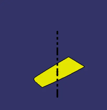
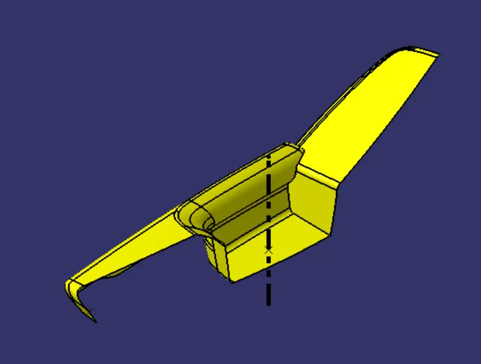
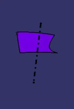
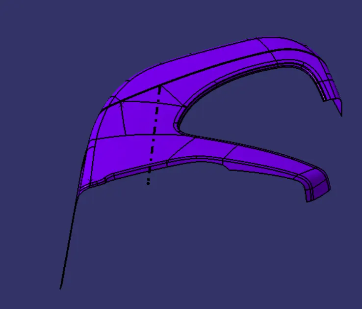
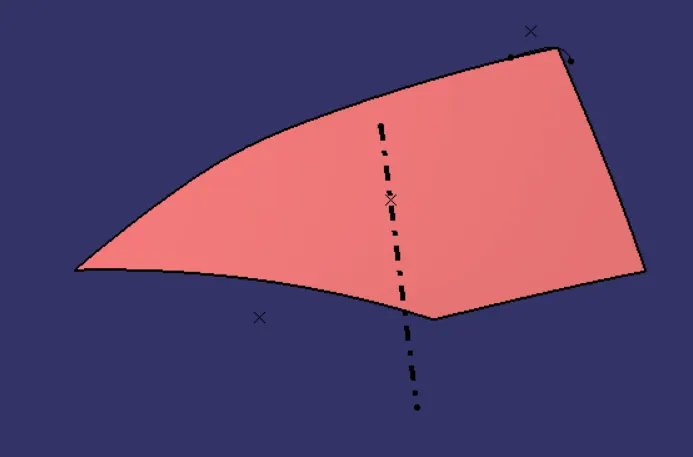
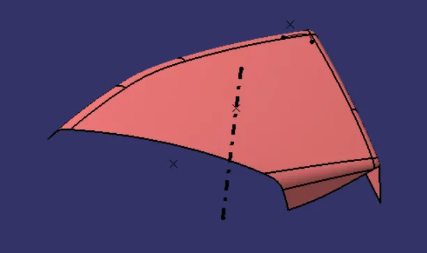
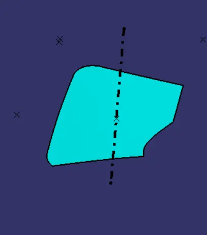
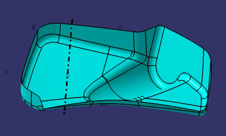
Tooling axis is the direction in which the core and cavity opens and closes. In order to construct the Class B and Class C surfaces, it is crucial to determine the tooling axis from a Class A surface since this axis serves as a reference line for the draft angle.
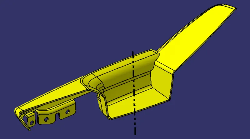
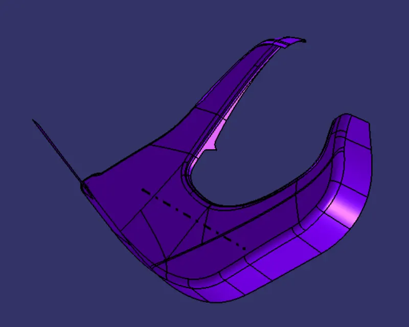
In this challenge, the tooling axis is discovered by just sketching a line perpendicular to the surface as shown below.
BISECTING METHOD :
- It's a method of finding tooling axis. In order to find the tooling axis we need to under find the better tooling direction by analysing the body.
- Finding tooling axis should be in a manner which will reduce the manufacturing cost, like wise there will be some better tooling direction which can avoid the use of side core.
- If we get the better tooling direction as Z axis. Firstly find the tooling direction in X and Y axis if there are inclined surface to be considered this is achieved by intersection solid and bisecting method.
- After finding both the tooling axis in X and Y direction, bisect it to find the main tooling axis.
DRAFT ANALYSIS :
In order to recognise that our drafted component is at an angle that is higher than the typical draft angle, which is about 3 degrees, draft analysis is employed. Draft analysis is done using a tool in Catia called "Feature draft analysis." When you click on this tool, the window below will appear.
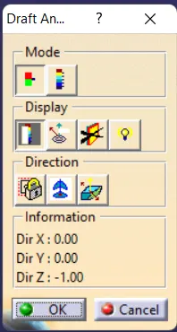
- In the mode section, there are two modes: the Quick analysis mode and the Full analysis mode. In this challenge, quick analysis mode is being used to visualise draft analysis.
- First, a tool named "Compass" from the direction category is used to define new draft direction. The direction of the draft is determined by positioning that compass above the tooling axis.
- Then by just clicking over the surface or the component we can visualize the colour corresponding to the angle as set in the draft analysis.
- There is an another tool which is used to find angles at running points. The tool is under display category, in that by selecting the tool named "Analyses under the running point" there by moving the cursor over the component gives the draft angle at that particular point on the component.
- There is an another tool to change the draft direction of the compass, which is under direction category next to the compass tool.
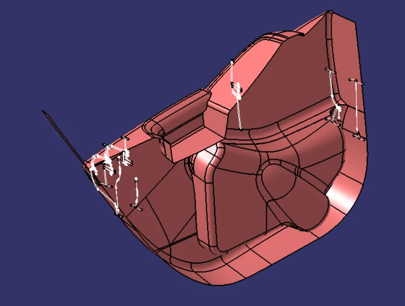
GIVEN CAD DRAWING WITH MASTER SECTION :
TOOLING AXIS OF EACH CLASS A SURFACE :
DOOR ARM REST :
DOOR LOWER SUBSTRATE :
MAP POCKET :
BOTTLE HOLDER :
DRAFT ANALYSIS OF CLASS A :
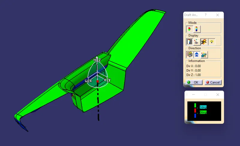
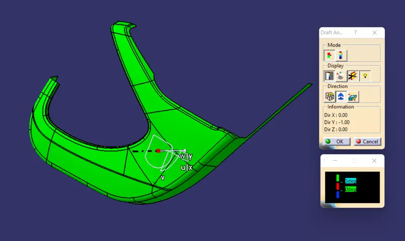
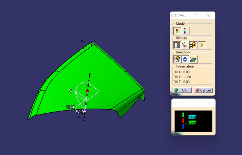
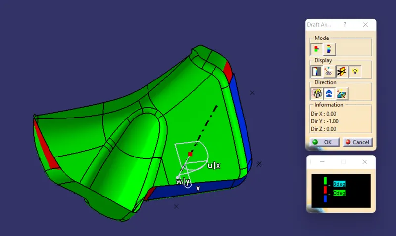
Draft analysis of the different class A such as Door arm rest, Lower substrate, Map pocket and Bottle holder has been done. In the analysis only Door lower substrate and Map pocket is following proper draft. The other class A surface like Door arm rest and Bottle holder should be corrected by the styling team. Details of draft analysis is shown below.
DOOR ARM REST :
DOOR LOWER SUBSTRATE :
MAP POCKET :
BOTTLE HOLDER :
THICKENED BODY CREATED AS PER THE MASTER SECTION THICKESS :
DOOR ARM REST :
DOOR LOWER SUBSTRATE :
MAP POCKET :
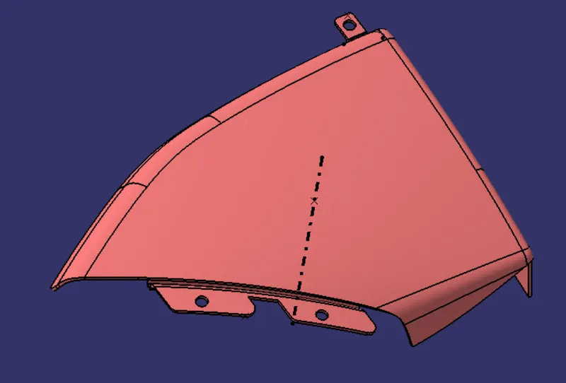
BOTTLE HOLDER :
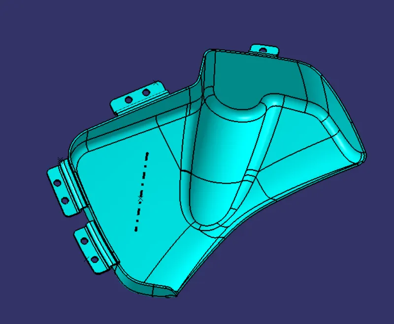
DRAFT ANALYSIS OF CLOSED BODY (PART BODY) :
DOOR ARM REST :
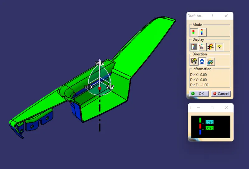
DOOR LOWER SUBSTRATE :
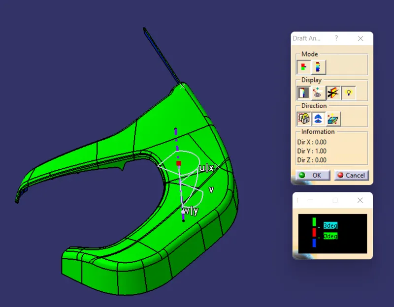
MAP POCKET :
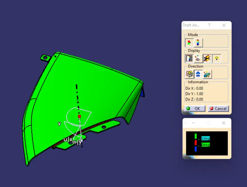
BOTTLE HOLDER :
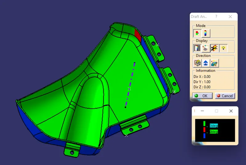
MOUNTING FEATURES CREATED AS PER DESIGN GUIDE LINES :
DOG HOUSE :
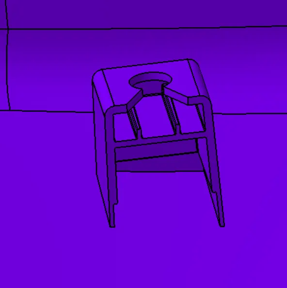
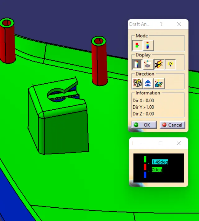
DRAFT ANALYSIS ON DOG HOUSE BY MAIN TOOLING AXIS OF DOOR LOWER SUBSTRATE :
Dog house draft analysis had done. From the figure shown below we can understand the draft analysis is not properly clearing with 1.5 deg but it's clearing with 1.49 deg.
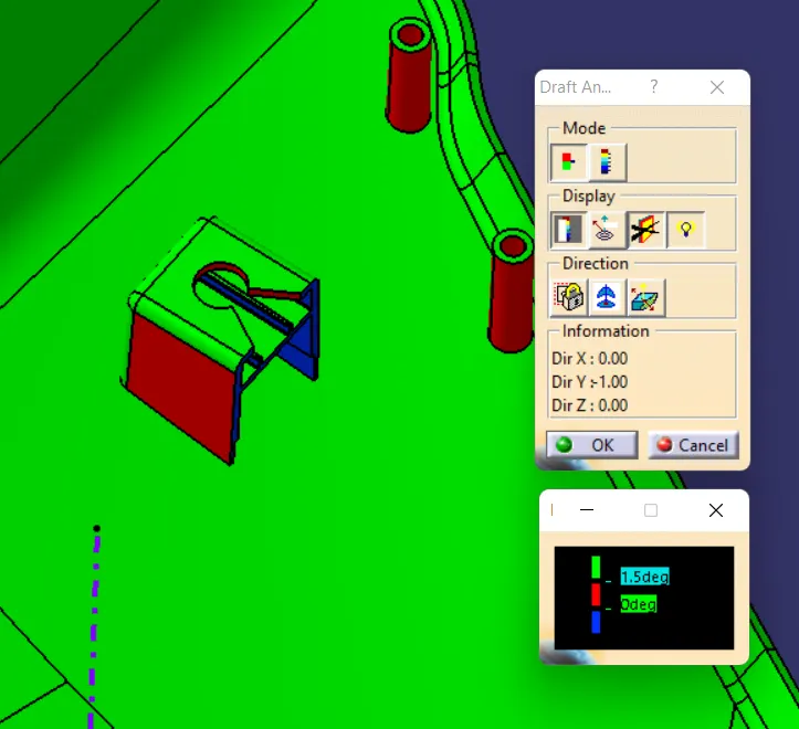
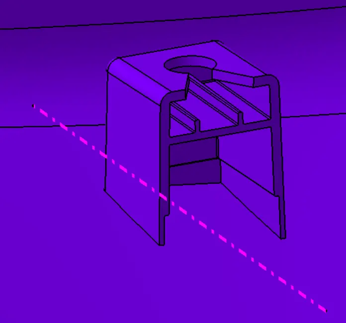
SIDE CORE TOOLING AXIS :
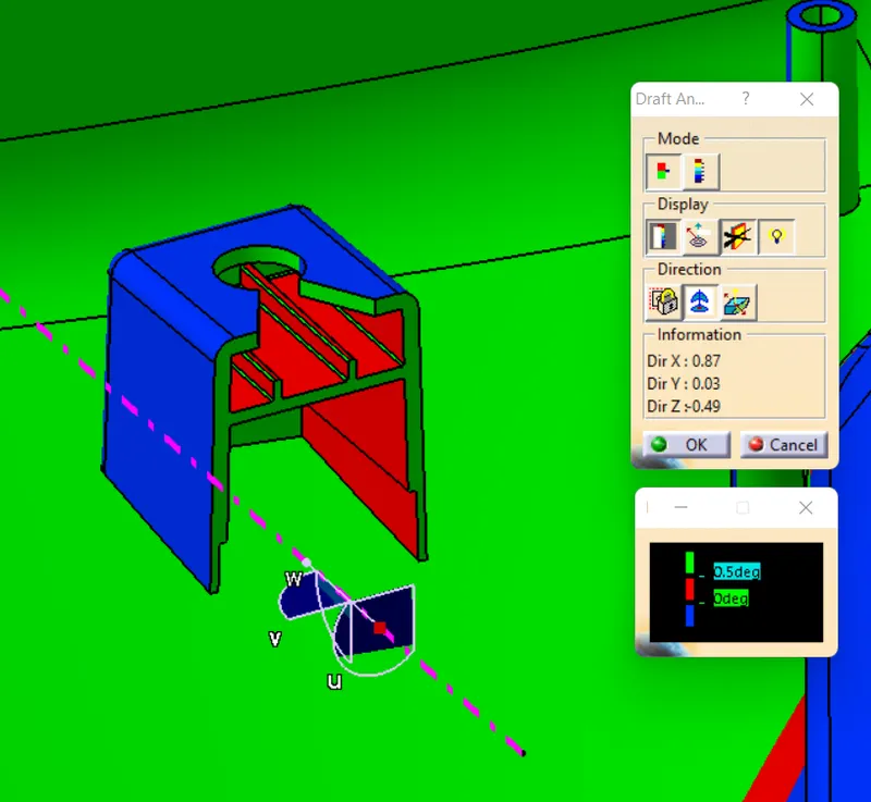
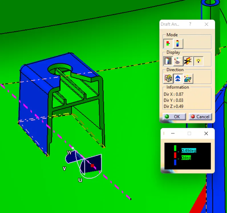
DRAFT ANALYSIS ON DOG HOUSE BY SIDE CORE TOOLING AXIS :
Draft analysis of dog house by side core tooling axis had done. From the figure it can see the dog house is not exactly clearing the draft angle of 0.5 deg but it's clearing with 0.49 draft angle.
HEAT STAKE :
DRAFT ANALYSIS ON HEAT STAKE :
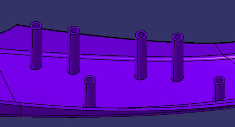
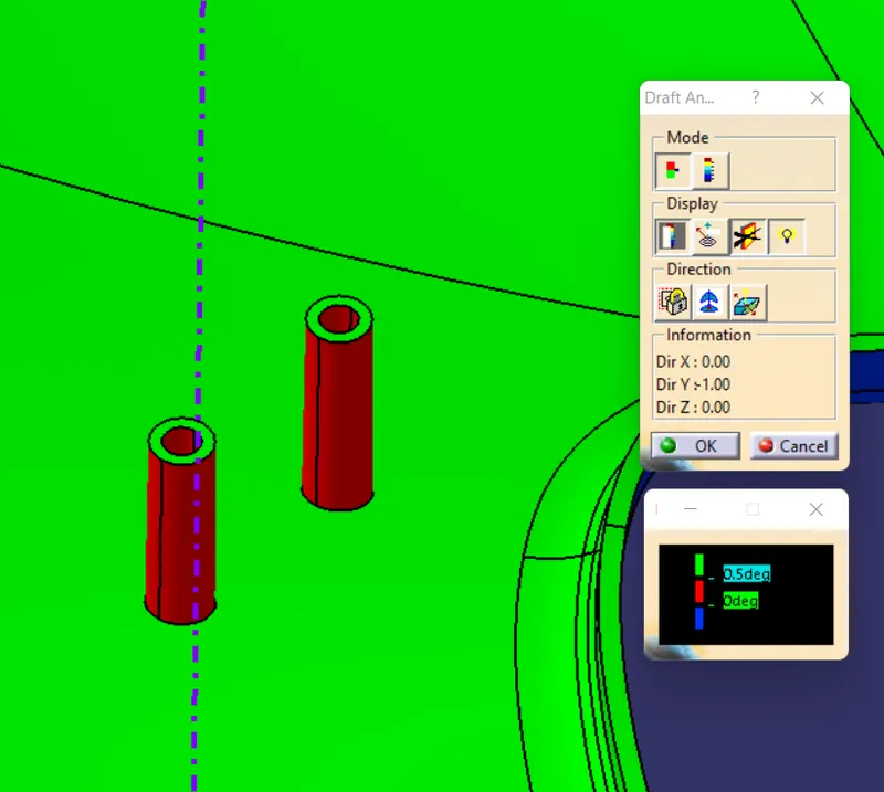
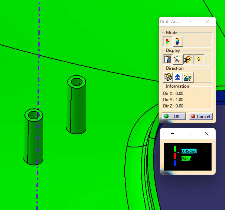
Heat stake draft analysis had done. From the figure shown below we can understand the draft analysis is not properly clearing with 0.5 deg but it's clearing with 0.49 deg.
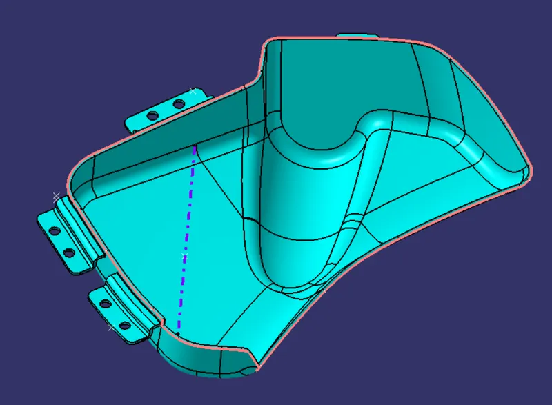
PARTING LINE FOR COMPONENTS :
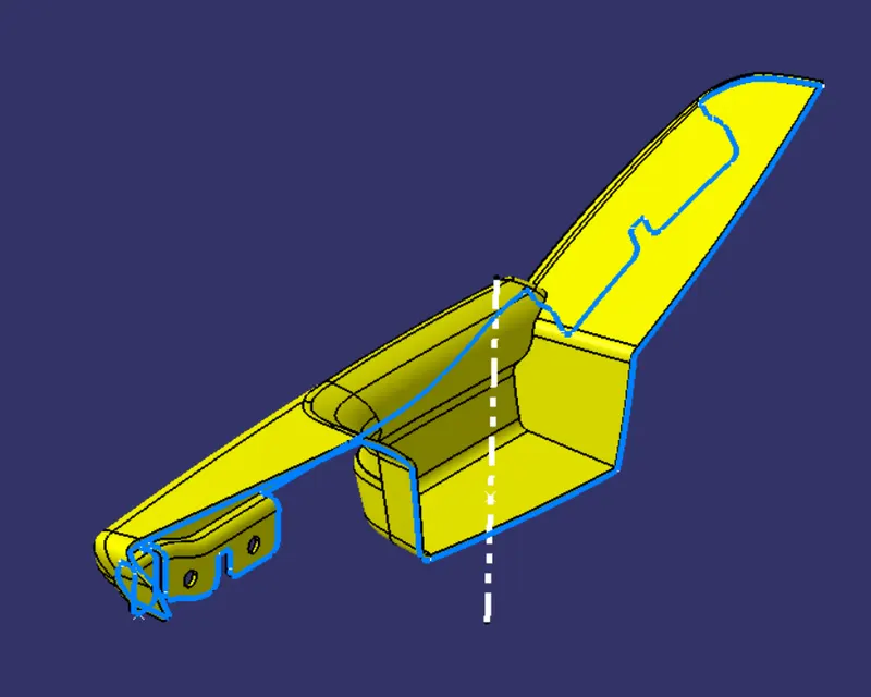
DOOR ARM REST :
DOOR LOWER SUBSTRATE :
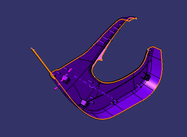
MAP POCKET :

BOTTLE HOLDER :
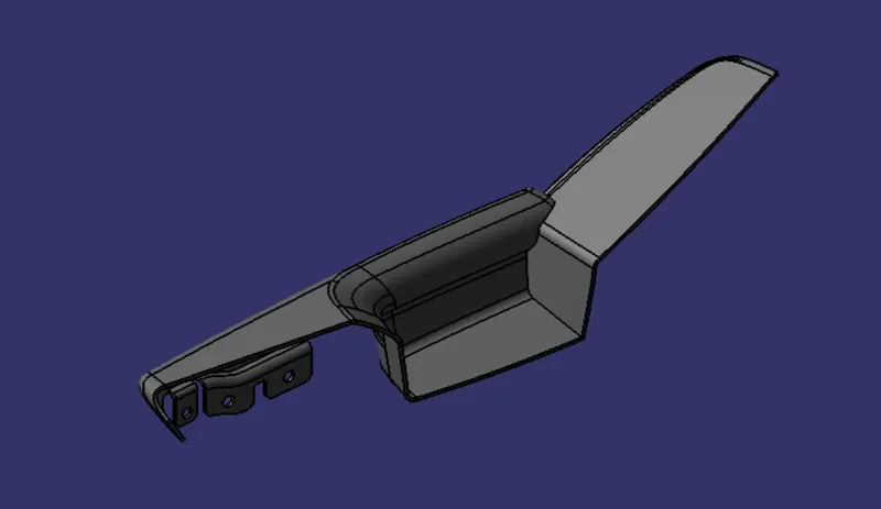
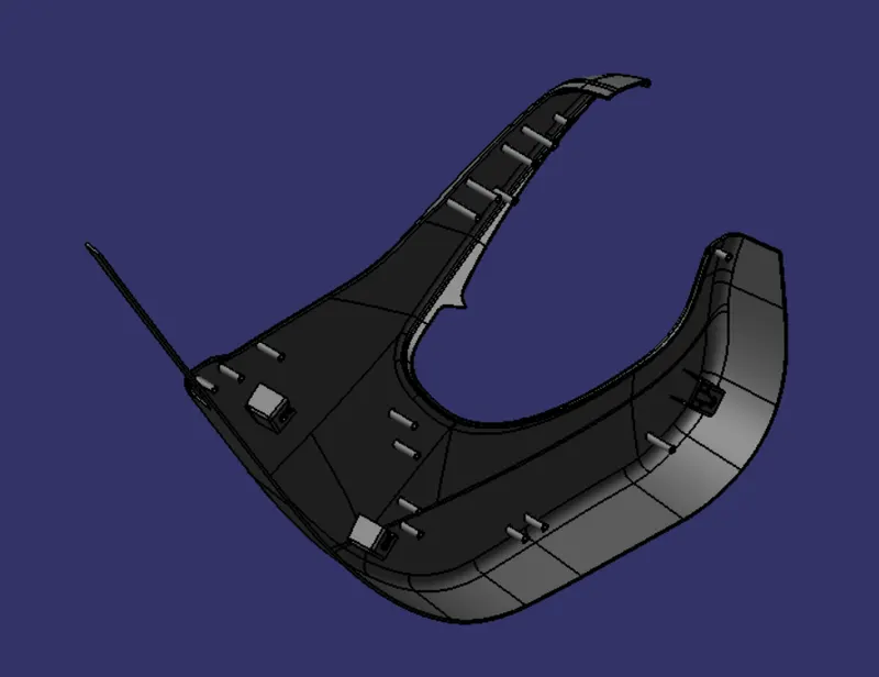
MATERIAL APPLIED : PLASTIC
DOOR ARM REST :
DOOR LOWER SUBSTRATE :
MAP POCKET :
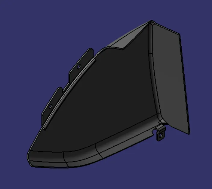
BOTTLE HOLDER :
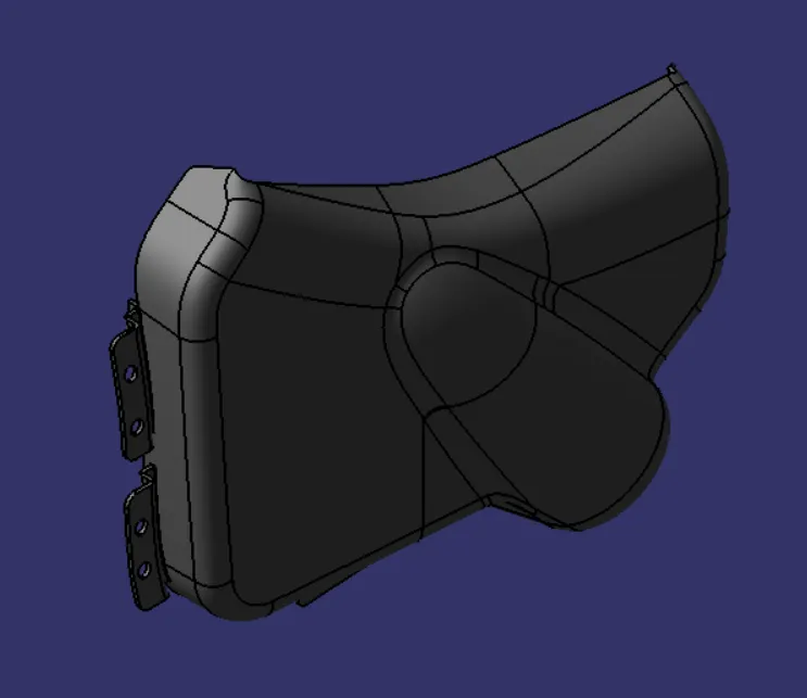
VIEWS :
ISOMETRIC VIEW :
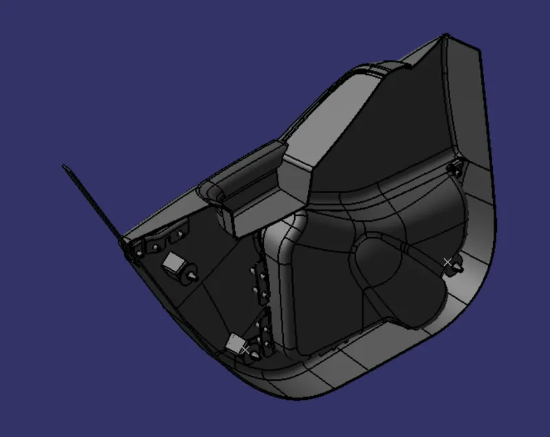
FRONT VIEW :
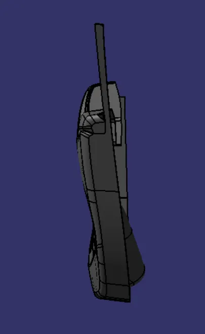
LEFT END VIEW :
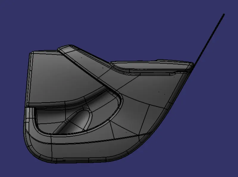
RIGHT END VIEW :
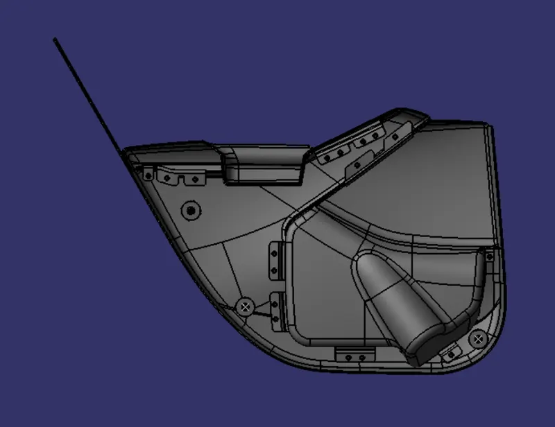
TOP VIEW :
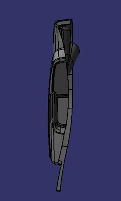
CONCLUSIONS :
- Door lower trim panel is created in the assembly workbench using the components like Door arm rest, bottle holder, map pocket, and lower substrate which are created using the surface and part workbench with proper draft. Parting line is also created.
- Finally plastic material is applied to the panel.