Hood design-Week 2
HOOD DESIGN IN SIEMENS NX CAD
OBJECTIVE :
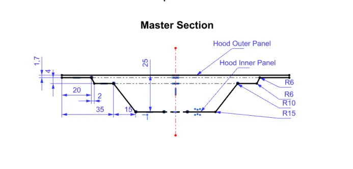
Design Hood Outer Panel, Inner Panel and the necessary reinforcements by following the Master Section mentioned with the Design parameters explained in the videos.
INTRODUCTION :
A car hood, also referred to as a bonnet in some other countries, is the hinged cover that rests over the engine of a front-engine vehicle. It's purpose is to provide access to the engine for repair and maintenance. A concealed latch is typically used to hold down the hood. On vehicles with an aftermarket hood and on racecars, hood pins may be used to hold down the car hood. Hoods sometimes also contain a hood scoop, wiper jets, power bulge, and/or hood ornament. Car hoods are typically constructed from steel and sometimes from aluminum. Aftermarket car hoods may be constructed from various other materials, including carbon fiber, fiberglass, or dry carbon. Outer and inner panels, hinges, hood stays, latches, strikers, and other components make up a standard hood.
DATA TO BE USED :
Hood Thickness Information :
- Outer Panel Thickness = 0.75mm
- Inner Panel Thickness = 0.75mm
- Reinforcement Thickness = 1.5mm
COMPONENTS :
1. Hood Outer Panel :
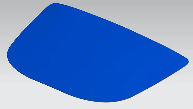
The outer panels of the car are what we see from the outside and are created by the styling crew. Additionally, these panels are insufficient to strengthen the surface. Therefore, necessary structures must be provided inside the panels.
In the hood design, we created the inner panel to provide the outside panel with the necessary strength while taking pedestrian safety into account. Additionally, there are certain reinforcements at the surfaces where the hinges and stricker are fixed.
With after the inner panel is finished, a hemming operation is used to link the outer panel and the inner panel. Some reliefs are offered at the corners during hemming.
2. Hood Inner Panel :
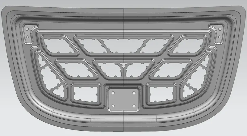
It is the component that gives the hood outer panel its strength. The master section dimension, which determines the size and shape of the main embosses, must be taken into account first. Later, we emboss the inside using our own optimal measurements, which helps to direct forces to the exterior in order to ensure passenger safety in the event of a collision. We also need to provide space for the hinge and striker before second embossing.
3. Reinforcement :
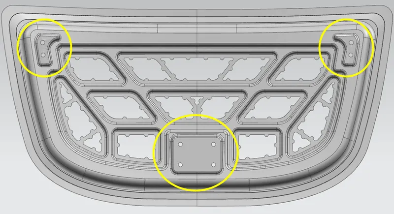
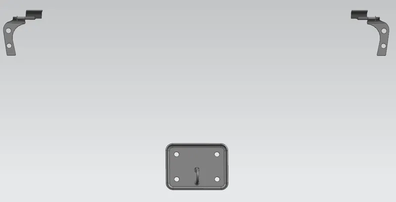
The inner panel's thickness is 0.5 mm based on the information provided. However, in some areas, such as the area where hinges and strikers are fastened, additional reinforcement is required to prevent deformation. 1.5 mm of reinforcement is present in these places in accordance with the data given. Where the reinforcements are placed is shown in the first figure, while hinges and strikers are shown in the second.
4. Latch Trajectory :
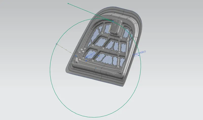
To determine the striker position, a construction curve is used. The hinges are first fixed in their proper positions, and then a line is drawn along the hinge axes of both hinges. Draw a circle with an appropriate radius, treating the line's midpoint as the circle's centre. Make sure the striker is aligned with the tangent drawn in the circle as shown in the picture while limiting it with the hood inner panel.
5. Emboss Definition :
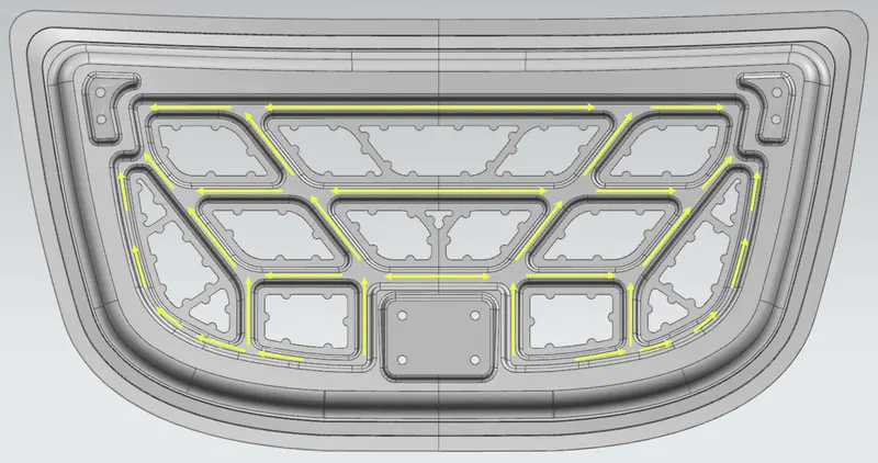
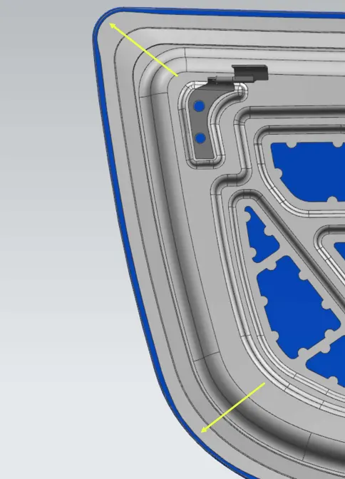
We provide several embosses in the inner panel, as indicated in the figure. These embosses serve to boost the strength and deflect the force. In order to ensure the safety of the passengers, embosses should be designed in a way that the force of a collision will be directed to the outside of the vehicle. Therefore, the emboss path should be angled outward in the form of a Y or V shape.
6. Mastic data :
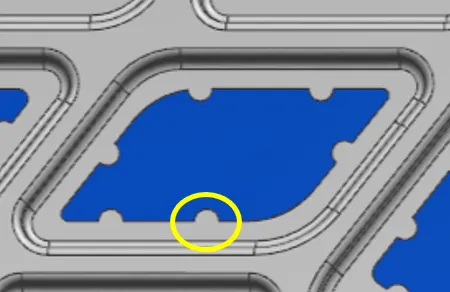
Here the material used to seal the gap between the inner and outer panel is called mastic. In some places, mastic is employed to achieve a perfect bond between the inner and outer panels because the hemming method used to connect the outer panel's boundary with the inner panel is insufficient to achieve this. Other joining techniques, like as riveting or welding, cannot be used since they will result from the outer panel's visual appeal. The mastic is provided in some of the embossed sections in the picture, where semi-circular geometry is projected. The effect of the mastic will be visible in a circle with an 80 mm diameter. The mastic will initially take the shape of a paste and eventually transform into a rubber form. This will not only aid in creating a flawless bond but also lessen vibration.
7. Deep Drawing :
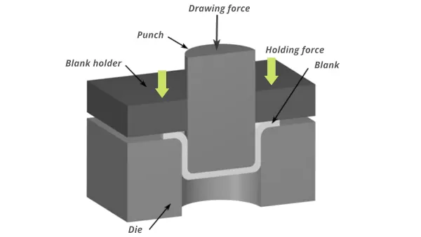
Deep drawing is a sheet metal forming process in which a sheet metal blank is radially drawn into a forming die by the mechanical action of a punch. It is thus a shape transformation process with material retention. The process is considered "deep" drawing when the depth of the drawn part exceeds its diameter. This is achieved by redrawing the part through a series of dies. The flange region (sheet metal in the die shoulder area) experiences a radial drawing stress and a tangential compressive stress due to the material retention property. These compressive stresses (hoop stress) result in flange wrinkles (wrinkles of the first order). Wrinkles can be prevented by using a blank holder, the function of which is to facilitate controlled material flow into the die radius.
8. Hemming :
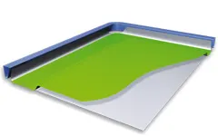
Hemming is a forming operation in which the edges of the sheet are folded or folded over another part in order to achieve a tight fit. Normally hemming operations are used to connect parts together, to improve the appearance of a part and to reinforce part edges.
In car part production, hemming is used in assembly as a secondary operation after deep drawing, trimming and flanging operations to join two sheet metal parts (outer and inner) together. Typical parts for this type of assembly are hoods, doors, trunk lids and fenders.
The accuracy of the hemming operation is very important since it affects the appearance of the surface and surface quality. Material deformations, which occur during the hemming process, can lead to dimensional variations and other defects in parts. Typical hemming defects are splits or wrinkles in the flange, material overlaps in the corner areas or material roll-in. This is why it is important to use simulation tools in order to, on the one hand, better understand the hemming process and, on the other hand, significantly reduce the number of “trial and error” loops during tryout und production.
There are various types of hemming operations:
- Conventional die hemming
- Roll hemming
Conventional Hemming :
In conventional die hemming, the flange is folded over the entire length with a hemming tool. Normally the actual hemming is a result of a forming operation in which the flange is formed with a hemming tool after the drawing and trimming operations have been completed. The formed flange is then hemmed in several process steps. These steps include, for example, the pre-hemming and final hemming depending on the respective opening angle of the flange. Production plants for conventional die hemming are very expensive, but the cycle times are very low.
Roll Hemming :
In roll hemming, the hemming roller is guided by an industrial robot to form the flange. Roll hemming operation can also be divided into several pre-hemming and final hemming process steps. Roll hemming is very flexible to use and tool costs are significantly lower as compared to those of conventional die hemming. However, the cycle times are much higher since the hemming is realized using a hemming roller which follows a defined path.

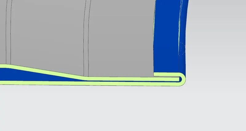
Hemming is carried out as depicted in the figure in our project. In order to prevent damage to the hood's corners during the hemming process, the corners must be relaxed slightly. The corners are given a 3 mm relaxation.
9. Final Assembly of Hood :
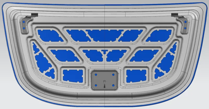
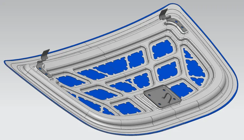
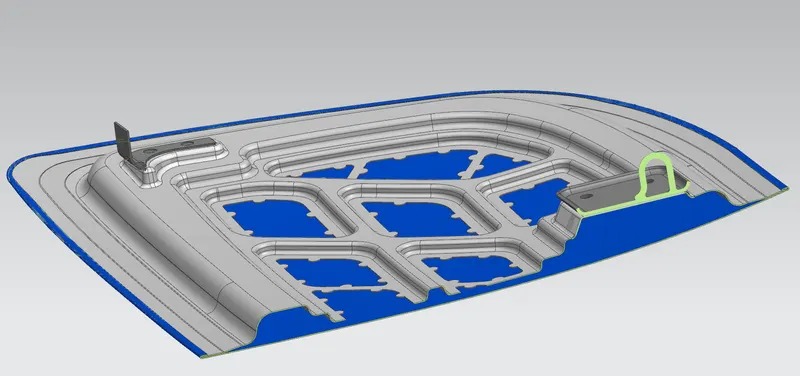
Note :
A zip file named hood design challenge is also attached with this, in that, file name called hood design contains the full assembly.