Roof Design
AIM: To a given roof styling, create essential flanges and reinforcements.
Objective: To develop the essential flanges and reinforcements with appropriate dimensions and checking
draft by using draft analysis. Calculating the heart distortion, snow load, and section inertia on the using
NXCAD.
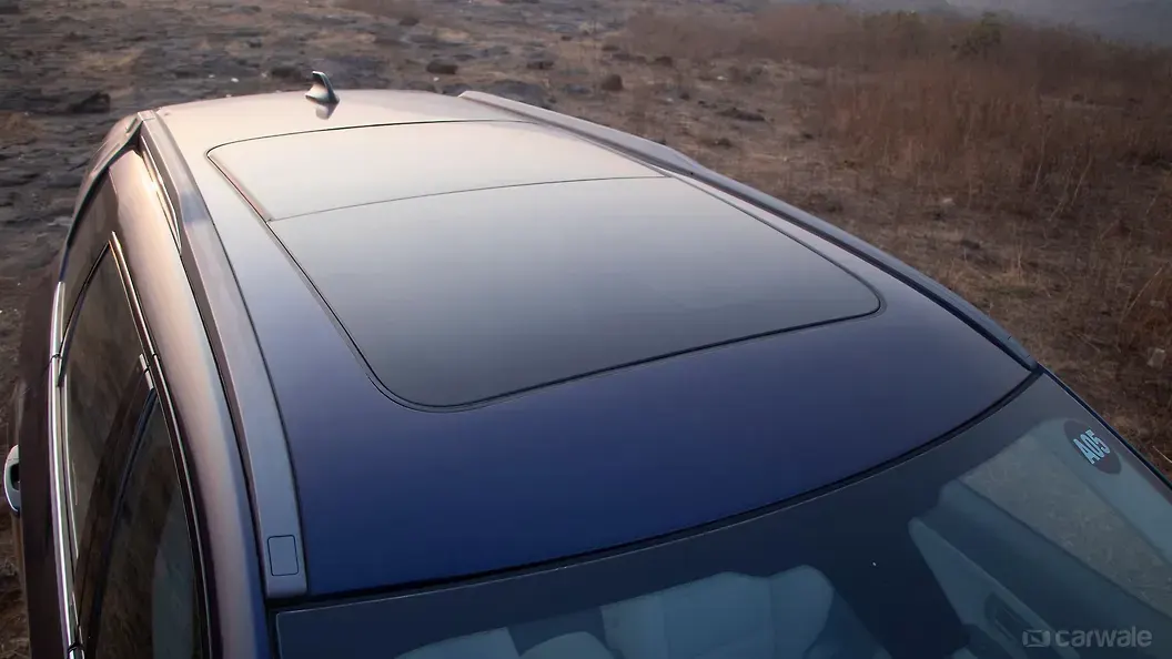
Introduction: An automobile roof or car top is the portion of an automobile that sits above the passenger
comportment, protecting the vehicle occupants from sun, wind, rain, and other external elements.
Types of car roofs:
- Convertible roofs
- Hardtops.
- Sunroofs.
- T-tops.
- Targa tops.
- Vinyl roofs.
The following factors should be considered for the roof design:
- Visibility criteria
- Head clearance for comfort
- Safety Parameters
- Draft analysis
- Heat distortion and Snow Load
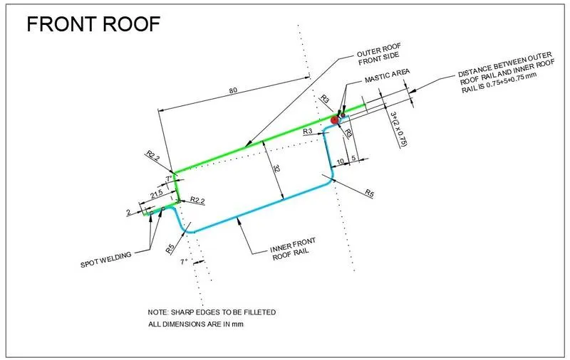
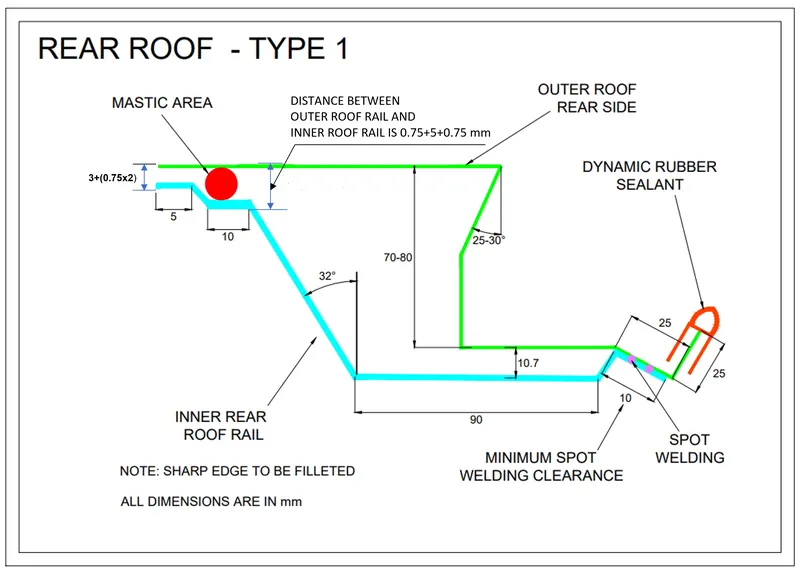
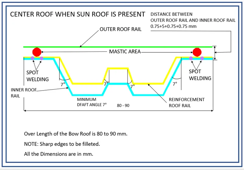
*To design a roof with reinforcements we have a master sketch and some reference images
Front Roof:
*Master section of the Rear Roof Rail
- *Front Roof Rail:
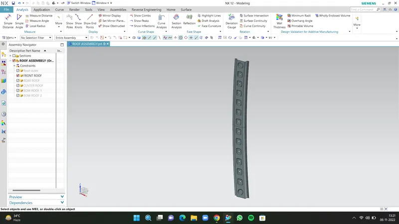
With the help of a master sketch we designed a front roof with proper dimensions and created embosses to strengthen the part and brackets given for mounting.
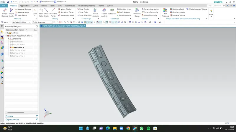
*Rear Roof Rail-
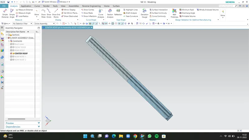
*Center Roof-
*Bow Roof 1-
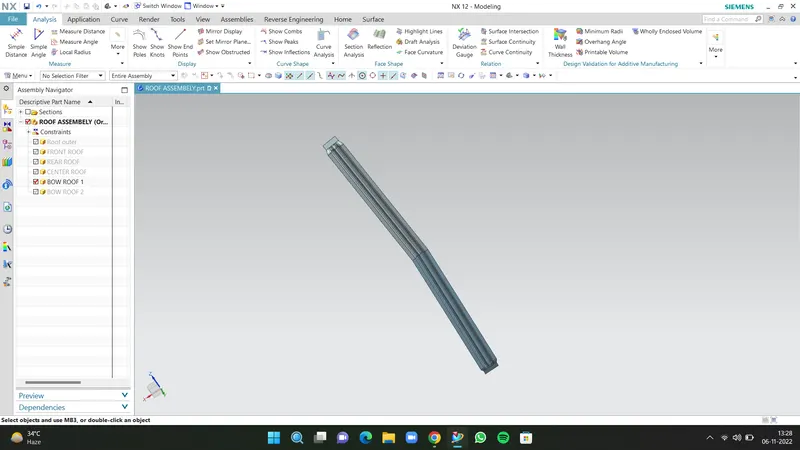
*Bow Roof 2-
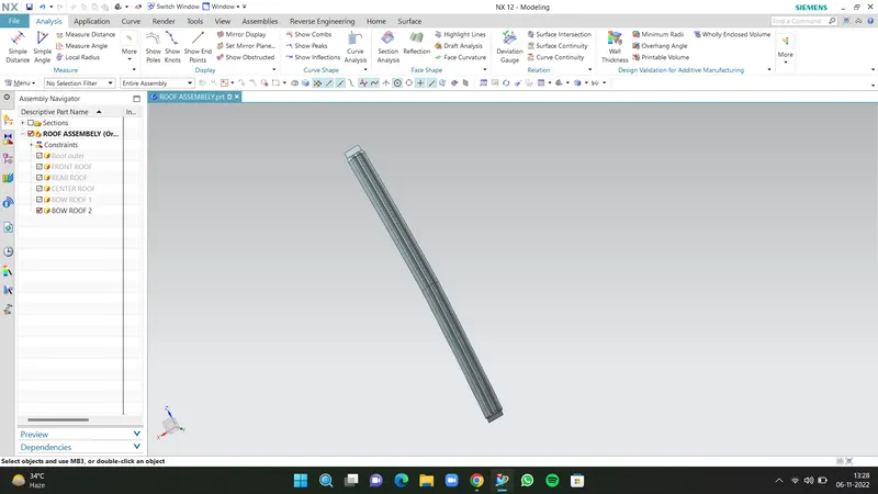
*Assembly:
Front View-
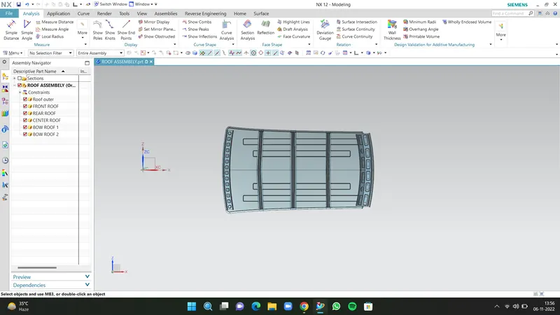
*Top View-
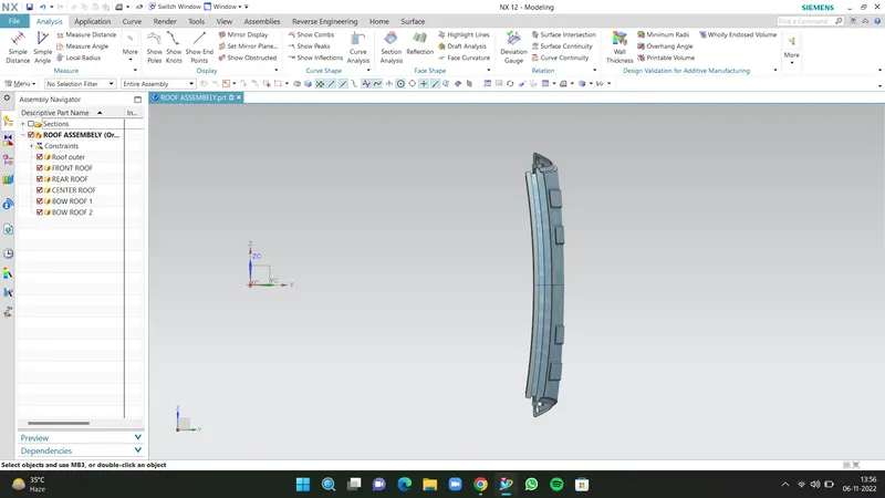
*Isometric View-
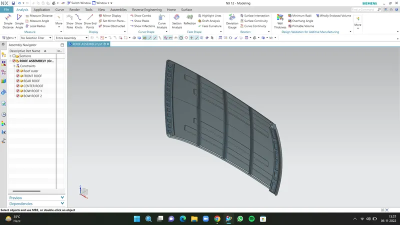
*Side view
Heat Distortion Calculations:

We have a data to calculate

W = [1.73 x 10^(-3) x L] + [1.85 x 10^(-8)  x (R^2)/t] + [ 1.10x10^(-3) x l] - 2.68


Judgement Condition : OK< 2.7> 3.1

Where

L = Roof Length in X-Direction[mm](Roof dimension in 0-Y)

R = Roof curvature

      R = 2(Rx*Ry)/(Rx+Ry)

Rx = X curvature

Ry = Y curvature

t  = Roof plate thickness [mm]

l = Bow Roof Span [mm]


Here we have to find out the RX and Ry values. To find that

Create a sketch on the top roof and draw a horizontal line at the centre.
Then offset this line below 300mm and called it the -3Y line.
From the _3Y line offset 100 mm above and below and convert all these lines into reference lines.
Draw the vertical lines at the middle of each reinforcement and offset it to 100 mm both sides.
Intersection point is created where the lines are met.
Project these points to the outer roof panel.
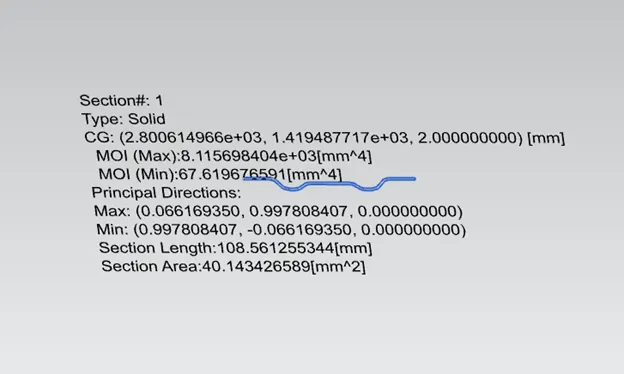
*To find out the geometrical moment of Inertia, we created an intersection curve and used the section inertia command.
*Bow roof 1:
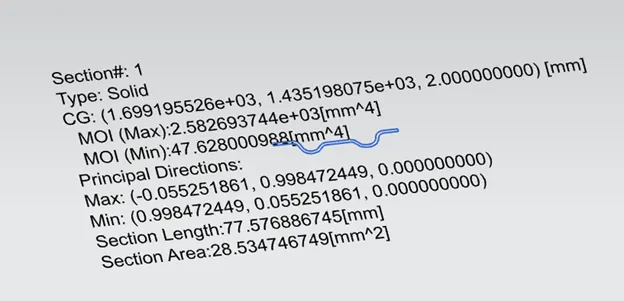
*Centre Reinforcement:
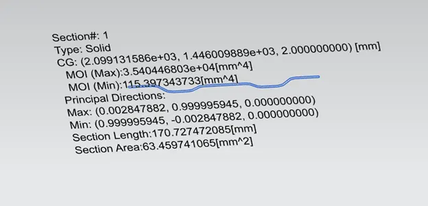
*Bow Roof 2:
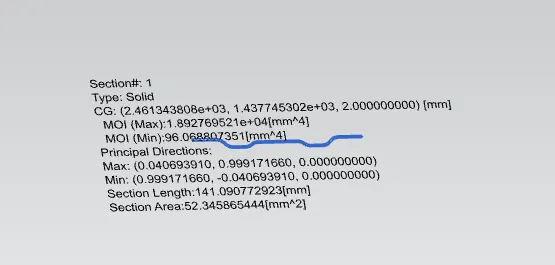
*Bow Roof 3: