Fender Design - Wheel Arch Challenge
INTRODUCTION-
Wheel arc calculation is necessary for the fender design to pass the local regulation which is based on the local road conditions.
The wheel arch is a semi-circular area in the fender, which houses the wheel well. It should have sufficient clearance between the tire and the wheel arch. So, that it doesn’t touch the wheel arch area during the suspension. The clearance value differs from region to region, here are a few regulations.
*Japan Regulation Standard-
The clearance value will be more than 5mm at 30 degrees forward and 50 degrees backward from the central vertical line.
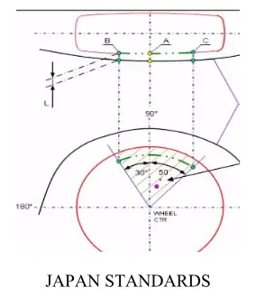
FIG.1 JAPAN STANDARDS-
*European Regulation Standard-
The clearance value will be more than 10mm at 30 degrees forward and 50 degrees backward and line 150mm above X-axis and Mid-point between 50 degrees and the line above 150mm.
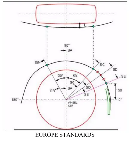
FIG.2 EUROPE STANDARDS
*US Regulation Standard-
Make clearance check details on all positions from -10 to 180 degrees. All values must be greater than 5mm. The Clearance Value will be more than 5mm at line 30 degree forward and 50 degrees backward from the central vertical axis.
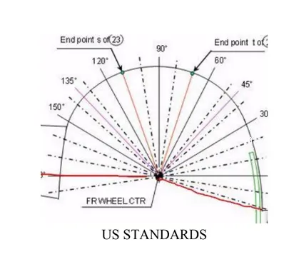
FIG.3 US STANDARDS
**WHEEL ARC CALCULATIONS** This is carried out for pedestrian safety of the car, here by using the European regulation's requirement to define the design given for calculation.
As required to plot the coordinates,
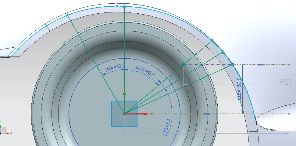
FIG.4 Plotting the checking point on the plane.
In FIG.4 the following Requirement coordinates SB, SB, SC, SD, and SE are plotted using the angles and dimensions according to the requirement standard.
Next, the points are checked if they provide a gap of 10mm from the outer part of the fender to the outermost part of the tier, if it is more than 10mm it meets the safety requirement if it is below 10mm it doesn’t meet the standard.
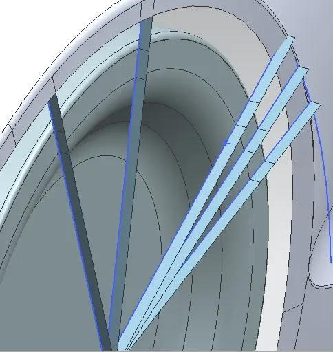
FIG.5 Law extension of 10mm toward the fender
In FIG. 5 you can see the law extension of 10mm towards the fender is done, we can see that SA and SB have a clearance of more than 10mm whereas the remaining checkpoints don’t meet the standard.
The above figure shows the following result
- SB plot satisfies the 10mm distance
- SA plot satisfies the 10mm distance
- SC plot doesn’t satisfy, there is 3mm clearance which doesn’t go with the standard.
- SD plot doesn’t satisfy, there is 0.25mm clearance which doesn’t go with the standard.
- SE Plot doesn’t satisfy, there is -3.4mm clearance which doesn’t go with the standard.
Aim: To determine whether or not the given design meets European requirements.
Given Design:
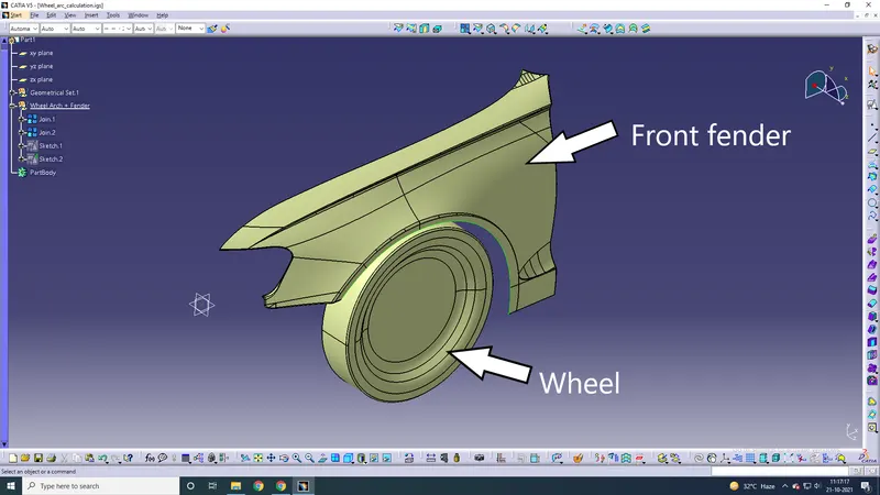
European Regulations Requirement:
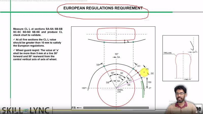
- Consider the fender and wheel contours.
- Make a circle in the wheel's center.
- Create perpendicular axes in the horizontal and vertical directions starting at the center of the wheel.
- Draw two lines 50 and 30 degrees apart from the center.
- Make a mark 150mm from the horizontal on the fender line.
- Draw a line from the center outward to this location.
- Then draw a line exactly halfway between the line at a 50-degree angle and the line at the 150-mm mark.
Measure the lengths between the wheel circle and the fender curvature. To comply with European regulations, all of these should be larger than 10mm.
- Second, the horizontal distances between the SA, SB, and SC positions and the fender curvature must be at least 5mm.
Check to see whether the design meets these criteria and if it meets the European Regulations Requirement.
Challenge:
A sketch has been made.
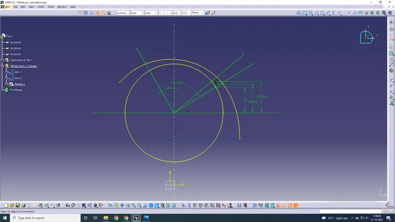
Now let us measure the distances between the points at the 5 sections.
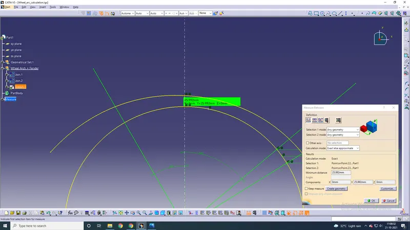
SA-SA
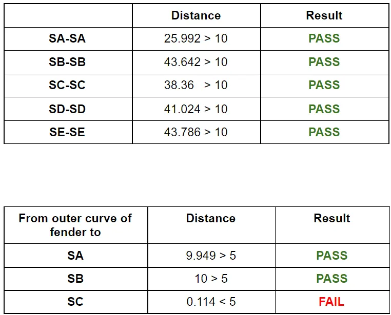
25.992 mm > 10 mm
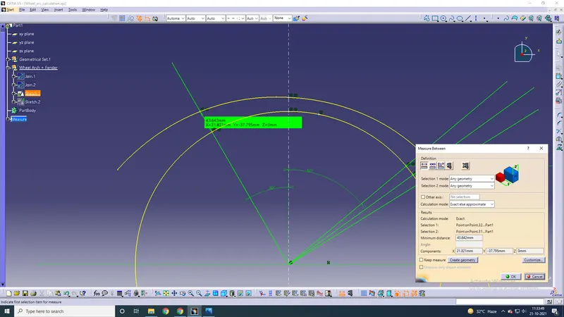
SB-SB
43.642 mm > 10 mm
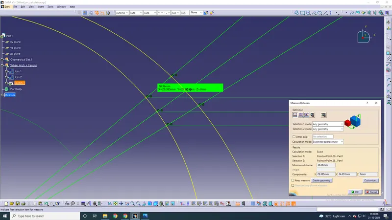
SC-SC
38.36 mm > 10 mm
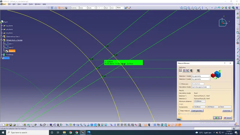
SD-SD
41.024 mm > 10 mm
SE-SE
43.786 mm > 10 mm
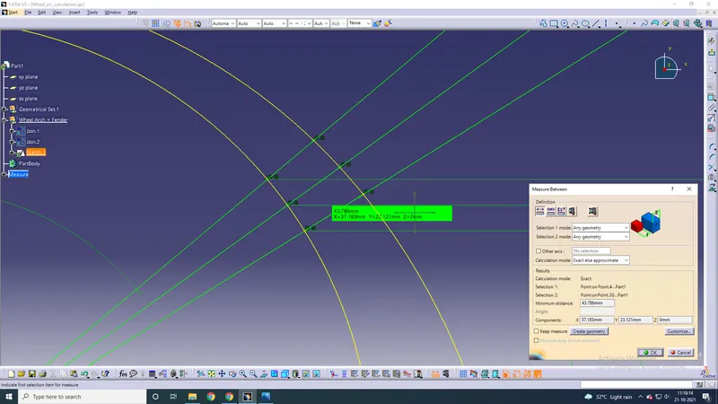
Next, measure the distance horizontally between the wheel and the fender. The SA point, SB point, and SC point should be at least 5mm away from this location.
Project the created sketch onto the wheel's axis.
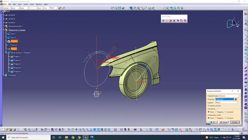
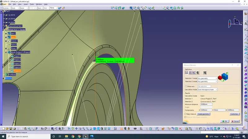
Distance between SA point and fender outer curve = 9.949 mm (pass)
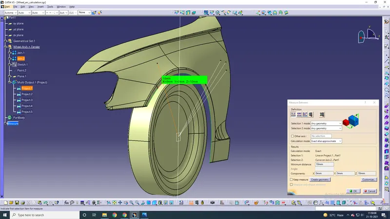
Distance between SB point and fender outer curve = 10 mm (pass)
Distance between SC point and fender outer curve = 0.114 mm (fail)
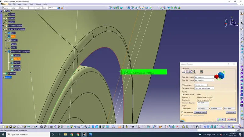
Table:
Conclusion:
The given design satisfies all European standards but one, i.e. the distance from the SC point to the fender curve (which is just 0.114 mm), which is way below the recommended 5 mm minimum distance. Therefore, this fender cannot pass European standards. The design should be reverted back to the class A designer telling him to modify the design and increase the gap there.