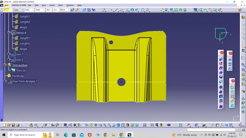
Week 9 - Challenge 1 - Base Bracket Design
AIM: Make the Base Bracket Plastic component using the provided Class-A surface. To begin, design the tooling axis for the specified Class A Surface while meeting the draught angle requirements, and then do the Draught analysis on the model.
Class A is the surface that the free-hand sketchers' concept sketches produce. The computer is then given the completed sketch, and software like Alias is used to turn it into a 2D surface. A Class A surface is this digital creation.
Class B is a duplicate of the class that the design engineer developed as a reference surface. a surface that is situated at a distance equal to the part's thickness.
Class C is a reference surface that the design engineer creates to connect the Class A and Class B surfaces, sometimes referred to as the surface's side wall.
Making two surfaces—B surface and C surface—from the provided Class A surface results in the creation of a part.
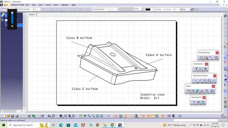
The method used to generate the model involves first creating a class B surface at a distance equal to the thickness (in this case, 2.5 mm), and then creating a vertical class C surface. The necessary component can then be obtained by trimming the three surfaces.
-
>) Procedures for creating the aforementioned component
*) The tooling axis was the initial duty in starting the model. The model was examined from all three planes, and the xy plane was chosen to produce the portion, with the hole taken into account and a point formed.
*) Using the same point as a reference, a dummy tooling line was generated. This line was afterwards used to generate a plane from which the intersection pattern was obtained.
*) The two slopes on either side of the intersection were employed to generate two more lines, which led to the creation of a bisector line, which became the main tooling axis.
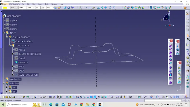
*) A geometrical set called a base bracket was established, and then the entire class A surface was retrieved independently.
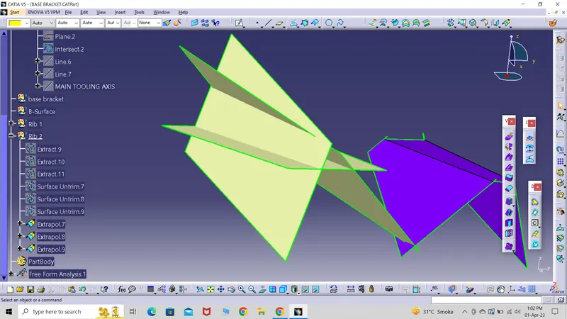
*) The extracted surfaces were then untrimmed to provide a complete surface, which was then extrapolated so that the trim command could be executed properly.
*) Two sides were trimmed at a time to obtain the below surface, which was offset by 2.5mm.
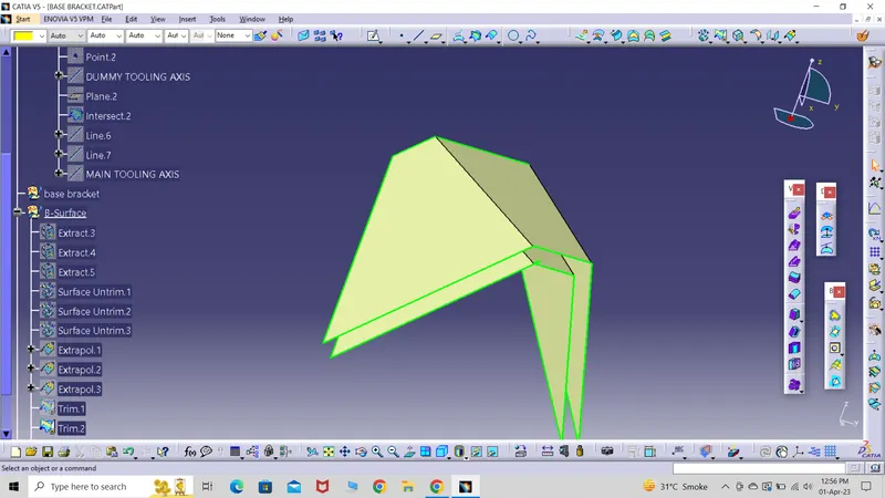
*) The same method was used to generate the second region, which was identical to the first region as indicated in the s.s.
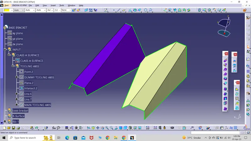
*) The central region was also extracted and offset to 2.5mm.
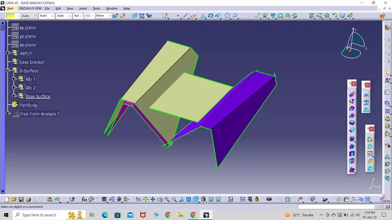
*)To get the necessary surface, the same area was cut to size using the previously developed two designs indicated above.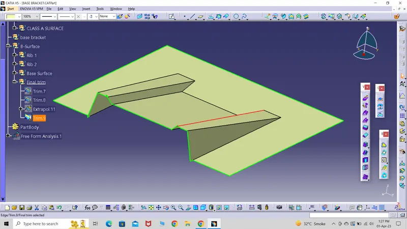
*) The surface B produced is an exact replica of class A, but it is 2.5 mm away and does not have fillets, thus fillets with a value of 3 + 2.5 = 5.5 mm were provided.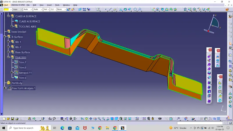
*) The class's surrounding region was also retrieved and extrapolated to trim the surface B with it.
*) Surface B is the final surface that was generated.
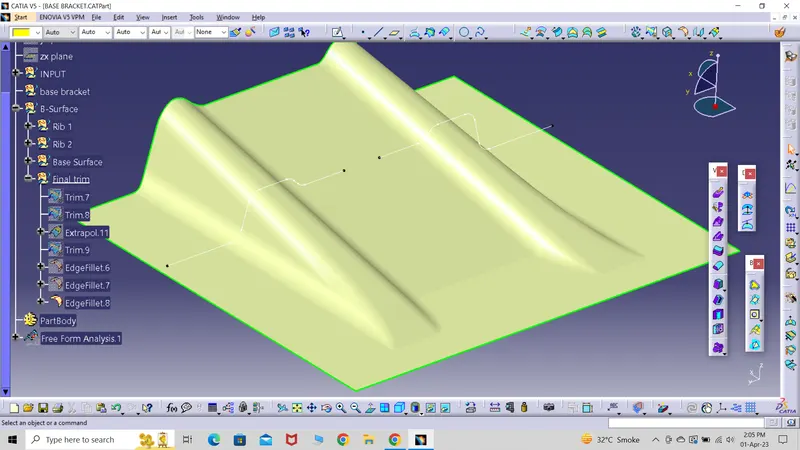
*) To trim the surface B with it, the class's surrounding region was additionally retrieved and extrapolated.
*) Surface B, the last surface to be formed, is displayed below.
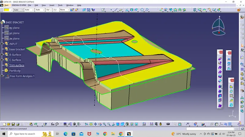
*) The boundaries were established, and they were both simultaneously swept in the same way as the two holes on the sheet.
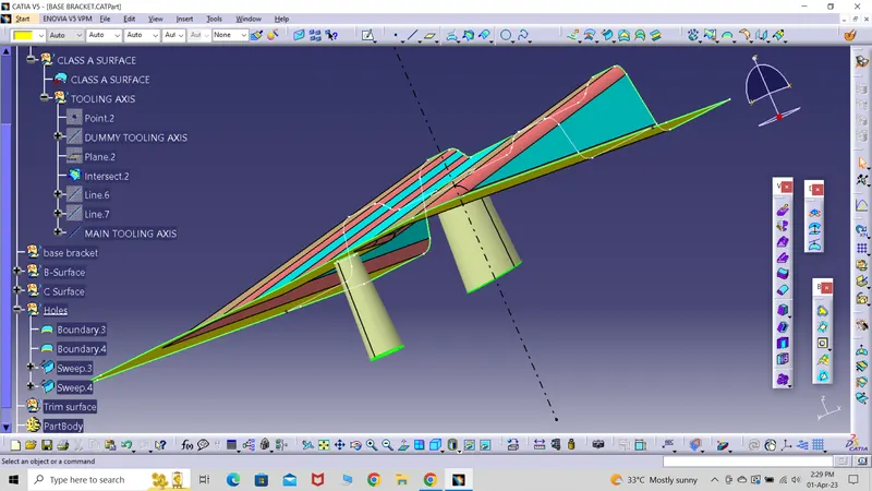
*) The necessary three surfaces were brought together while also taking into account any holes.
*) The final trim was applied to all three surfaces to create the item that is displayed below.
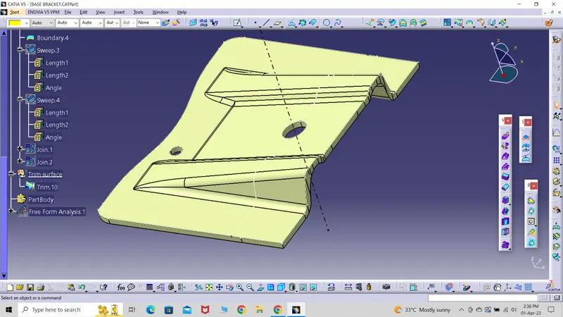
EXPLANATION OF BISECTING METHOD:
Using the dummy tooling axis, the bisecting approach is utilized to determine the proper tooling axis. The bisecting line is used in the bisecting technique, which either bisects the two lines or returns an error, indicating that the two lines are parallel to each other. To determine whether a surface is bearable, we intersect it with the appropriate plane and obtain a sketch consisting of two lines. Using the bisecting line option, we bisect the line, resulting in a line at the midway of the two lines. Similarly, we construct a tooling clearing axis for x and y, which will be used to generate the main tooling axis with the line command's bisecting line option.
DRAFT ANALYSIS
In plastic design, the draft analysis or angle that is considered in the OEMs is 3 degrees.
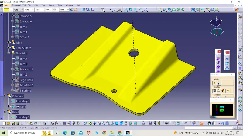
*) The first action to take was to choose the compass and position it on the tooling axis facing upward.
*) When you clicked on the surface, the entire component went green. If blue was seen, the analysis had been performed in the opposite manner simply by flipping the direction, draught analysis.
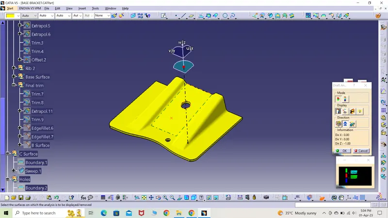
*) By selecting near body surface under the section Body option, the hollow section was later transformed into a solid body.
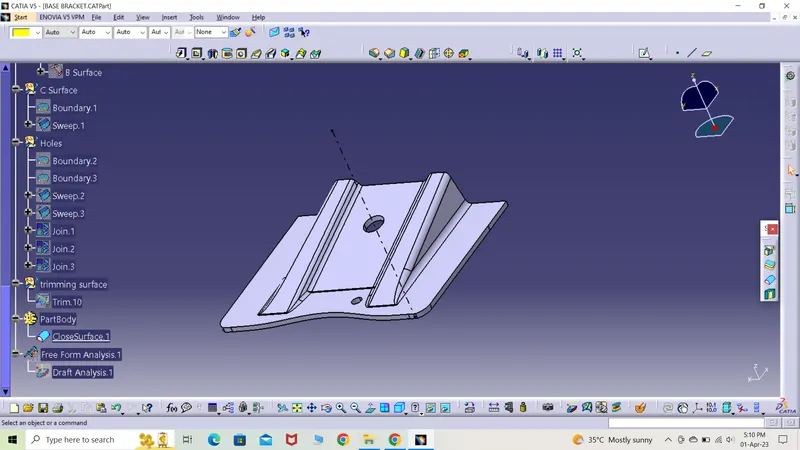
*) The solid portion of the draught analysis produced green and blue zones.
* The green area displays the moldable or toolable portion of the component, and the draught angle is 3 degrees.
* The blue colour zone indicates that while some OEMs may accept the part, others may require improvements due to the part's excessively high draught angle.
*) The absence of red in this instance indicates that the draught angle is less than 3 degrees, which makes production impossible or defective if it were to occur.
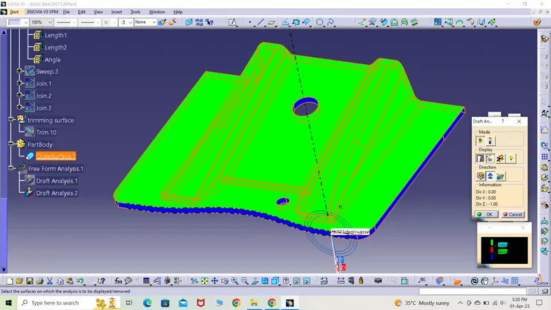
ISOMETRIC VIEW
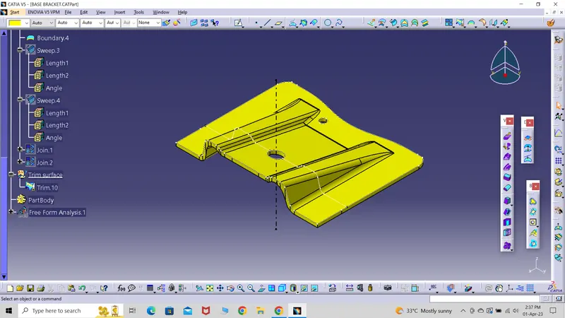
FRONT VIEW
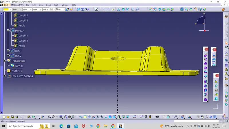
SIDE VIEW
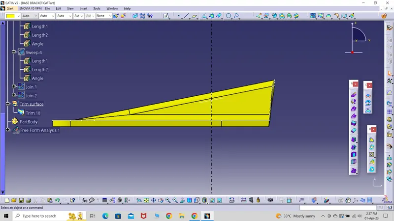
TOP VIEW