Week 10 - Challenge 1- Attachment Feature Creation (Ribs & Screw Boss)
Attachment Feature Creation (Ribs & Screw Boss)
AIM:
To make the Door Handle Component from the Class-A surface provided.
To create the tooling axis for the provided Class-A Surface while meeting the draught angle constraints.
To attach the component's B side features.
To run the model through the Draught analysis.
TOOLS USED:
- Boundary
- Join
- Multiple extract
- Bisecting line
- Trim
- Surface offset
- Draft analysis
- Intersect
- Surface sweep
- Close body surface
-
DESCRIPTION:
1. CREATING TOOLING AXIS
The direction in which an item is pulled out of a mould is known as the tooling direction. Basically, the mould is constructed out of two independent components. You have the Core side and the Cavity side. The Dye line or Tooling Direction is when the Core separates from the Cavity.
Dispatch the CAT component file.
-
Tooling Axis creation:
It is defined as the direction in which the mould/core and cavity open. Selection of the direction of the tooling axis depends on the ease at which components can be easily ejected.
By analysing the component the most easily ejectable direction is somewhere close to the Z direction,(might be inclined to it) so we have made a sketch on the YZ plane of Axis System) to create a bisecting line considering the 2 faces which might be difficult to be tooled.
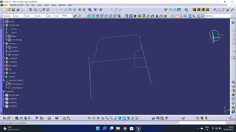
.
Then resultant tooling axis is created using the bisecting method.
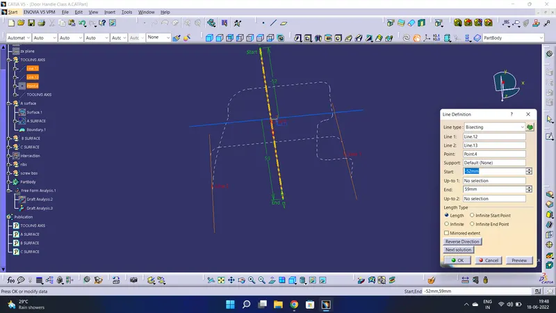
-
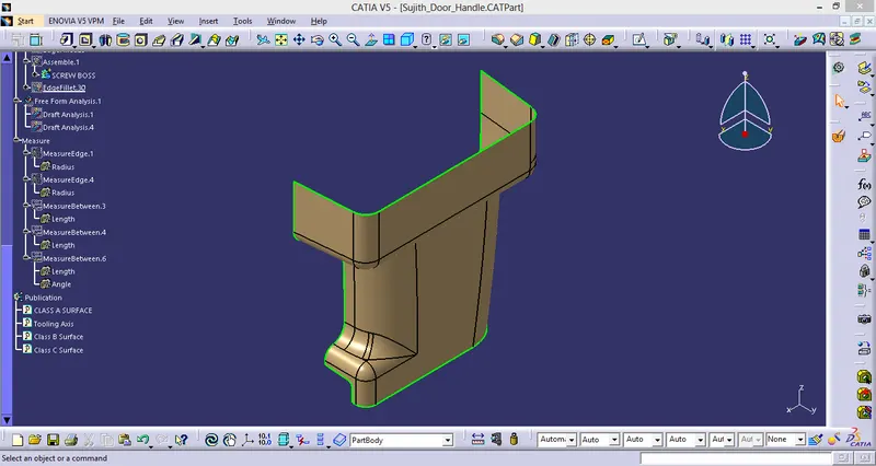
- Before clicking join and then preview, make sure there are no gaps between the surfaces.
Join the surfaces with a maximum tolerance of 0.003 mm if there is a gap. -
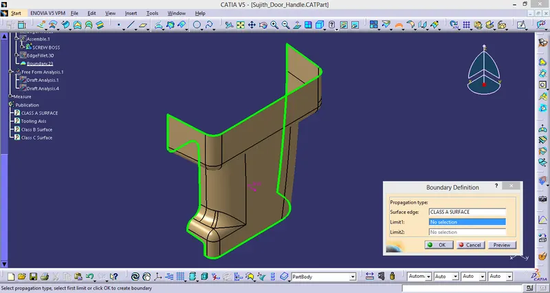
- Extract the boundary and dissemble the boundary.
- Find the correct tooling axis where the material don't interfere with the tooling axis and all the elements can be created.
- Create an axis system using at the centre of the switch Bezel.
-
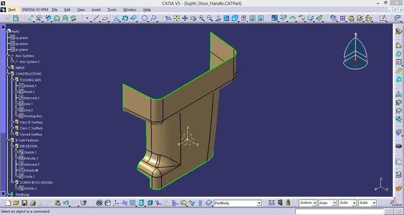
-
Divide the yz plane in half with regard to the class A surface.
Hide the class A surface and draw point-to-point lines across the questionable draughts.
Make a bisecting line from the two lines and point it to make a tooling axis.BISECTING LINES were employed to obtain the exact medium from the two sides in order to achieve the maximum positive draught angle.
-
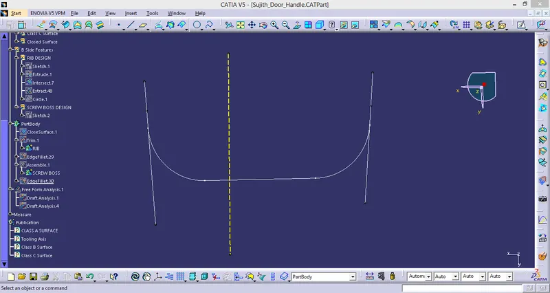
- The tooling axis is created for the component by bisecting two axis from x and y planes.
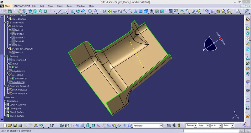
- The component is published to make it visible and easy to navigate.
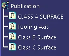
To publish the component, navigate to tools > publications and pick the tooling axis and class A surface.
Under the primary section, a second tree structure is generated. -
- 3. DRAFT ANALYSIS
-
You can determine whether the section you sketched will be simple to remove using the Draught Analysis tool. In this kind of analysis, zones on the analysed element are identified by colour ranges where the deviation from the draught direction at any given position corresponds to predetermined values.
Go to customised view parameter, under mesh, check material, and then click ok before moving on to drat analysis.
Now select "analysis" and then "feature draught analysis" to add draught analyses.
Set the draught direction using the compass.
Change the draught angle on the colour scale to 3 degrees.
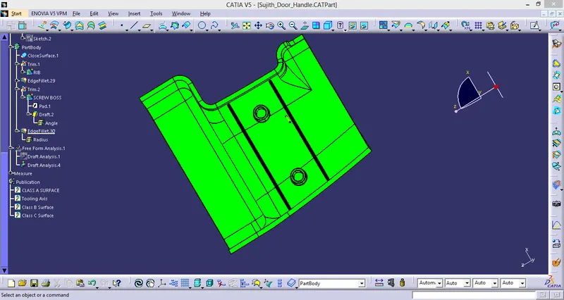
As a passing draught angle is shown, the component turns green.
Check the component's angle using running points. -
The purpose of draught analysis in design is to determine whether a CAD-created component can be manufactured under the given conditions. The created part needs to be simple to release from the mould, which is the major justification for the draught analysis. Additionally, it provides a sense of the draught angle based on tooling direction. Here, we're directing the tooling so that the component may be removed from the tool with ease. In the automotive industry, 3 degrees is recommended as the ideal draught angle for plastic components.
Hoods, fenders, roofs, side doors, and other parts are only a few of the components where draught analysis is done.
The draught analysis is a crucial tool since it enables the user to evaluate the draught on a variety of surfaces.
-
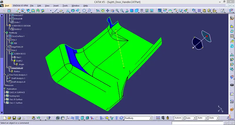
- The draft analysis is complete.
4. CREATING CLASS B SURFACE
- Extract the surfaces from the class A using multiple extract and untrim them.
- Use Extrapolate to make sure that all the untrims are properly intersected to trim and offset the surfaces to 2.5 mm to create the thickness.
- Trim the extra surfaces using trim command.
- Insert them into new geometrical set and name it with respective part names.
- Apply fillets to the model after creating the entire surface.
- If the edges are outside the fillet value will be added to the thickness of the component and if the edges are inside, the fillet value will be subtracted from the thickness of the component, for instance the thickness of the component Is 2.5mm the fillet value is 15mm so the outside portion value should be 17.5mm and inner eges should be filleted 12.5mm to get uniform thickness.
- Perform trims one at a time so that it will be clear to understand.
-
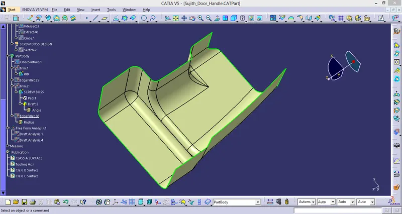
5. CREATING CLASS C SURFACE
- Extract the boundary from the class A surface using boundary command.
- Using disassemble tool to divide the boundary as the boundary contains domains.
- Use sweep command > choose profile type line > subtype as with draft direction > choose guide curve and draft direction > draft angle as 3 degree > preview.
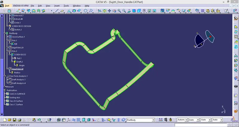
- After getting sweep then trim the output with class B surface to get final output.
-
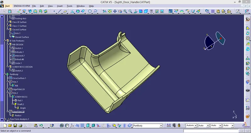
- Now open part design workbench and using close body surface create a solid of the component.
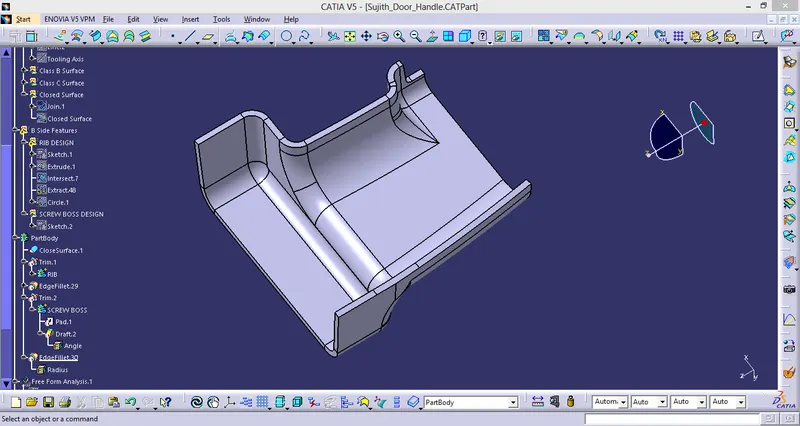
6. B SIDE FEATURES CREATION
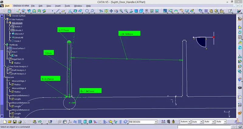
RIB CREATION
- Design Principle for Rib Creation
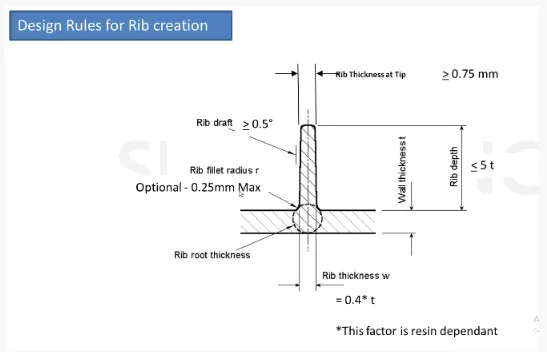
- Sketch Used For Rib Creation
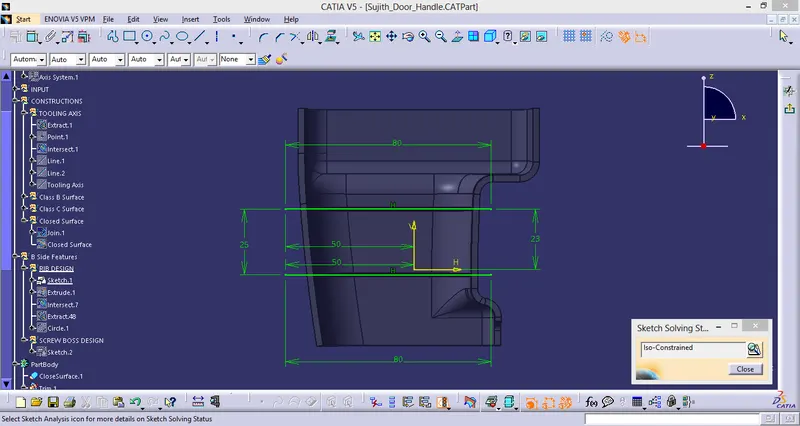
- RIB
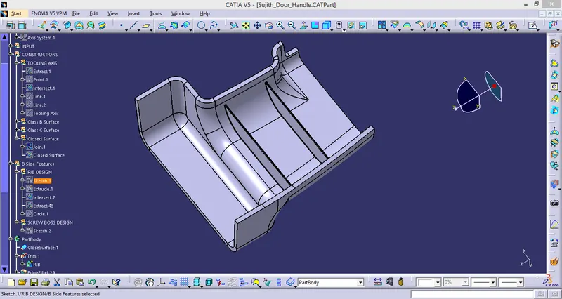
SCREW BOSS DESIGN
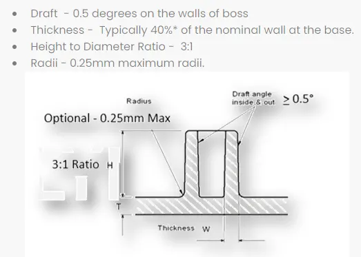
- Design Principle for Screw Boss Creation
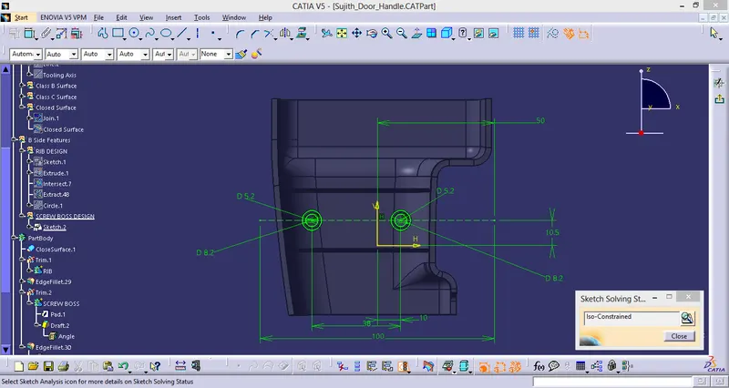
- Sketch Used For Screw Boss Creation
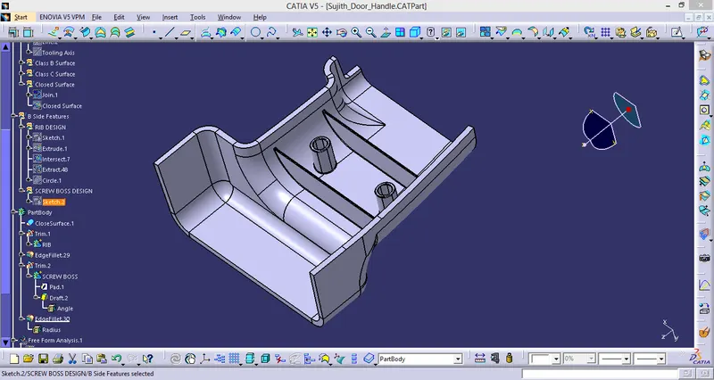
- SCREW BOSS
7. END DRAFT ANALYSIS
-
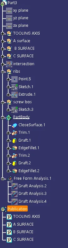
Tree image
8. 3D MODEL
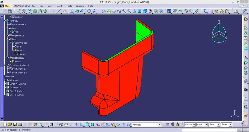
- ISOMETRIC VIEW
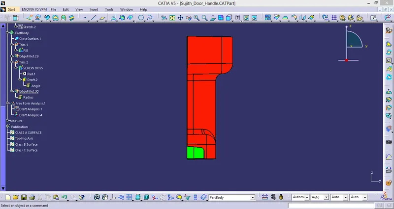
- FRONT VIEW
- LEFT SIDE VIEW
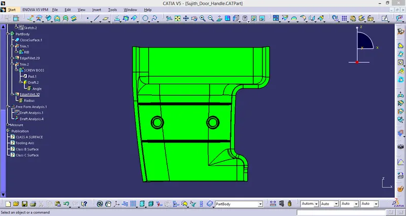
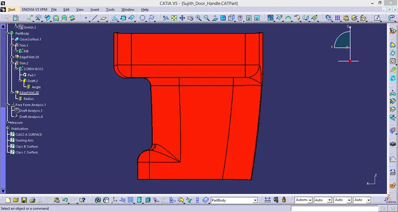
- RIGHT SIDE VIEW
CONCLUSION:
- The Tooling axis and the SolidCAT part with B Side Features is created from the given Class A Surface and Draft Analysis is Performed.