Week 9 - Challenge 2 - Switch Bezel Design
A switch bezel: is an automobile component that incorporates switches and buttons for controlling various operations such as window control, door lock, media, and so on. It is positioned on the inside of the door. The process for making the part was the same as for making the base bracket. The tooling axis was created using a Class A surface. The surface of class B was formed at a distance equal to the thickness of the surface of class A. Class C was used as the model's wall, and then all three surfaces were linked together and draught analysis was performed.
DESIGN OF THE TOOLING AXIS:
After being manufactured, the interior trim (switch bezel) must be ejected from the chamber of the mold with a minimum 3-degree draught angle.
In light of the foregoing consideration, the tooling direction is established using the bisecting approach.
A point was formed at the center of the base surface of class A, and an axis system was added to the topic with the current feature turned off.
The two inclined lines were then drawn inside the positioned sketch using the project intersection along the yz plane.
The two inclined lines were then used to draw bisecting lines.
The identical process is again carried out along the xz plane, except on one side there are no inclination lines, so
Steps in detail that are involved to create a switch bezel are as follows:
*) The first geometrical set was named tooling axis, and a sketch was made using the two planes as references. The sketch included two lines drawn in the planes, followed by a bisector of the two lines, which served as the main tooling direction.
*) All of the sketches were created with isometric constraints.
PROCEDURE FOR DRAFT ANALYSIS:-
- First the class-A – Surface is checked before creating the Class –B&C surface and finally the solid body must be analyzed. Both can be done by following the below procedures.
- By changing the view mode to custom view parameters – Material mode then the feature draft analysis is enabled.
- Then the compass was activated and placed with the tooling axis by dragging the red pointer and then locking it.
- Then, by selecting the quick analysis mode, the nominal value will be 3 degrees and checked for the component's draft angle.
- The green color area shows that it satisfies the 3-degree draft angle. If not satisfied then by using the Running point tool the area is measured and then altered to get a successful draft for the created tooling direction.
All Images are Given below.
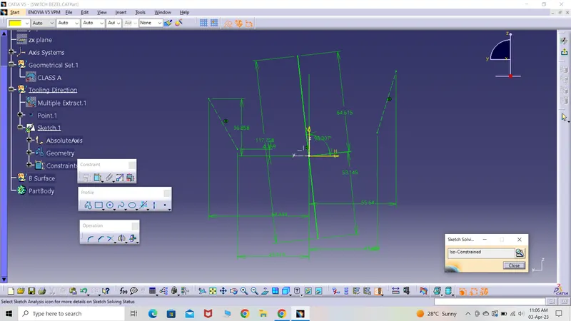
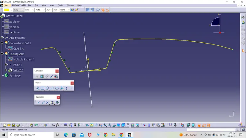
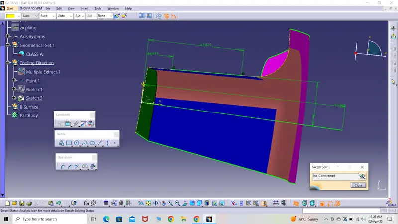
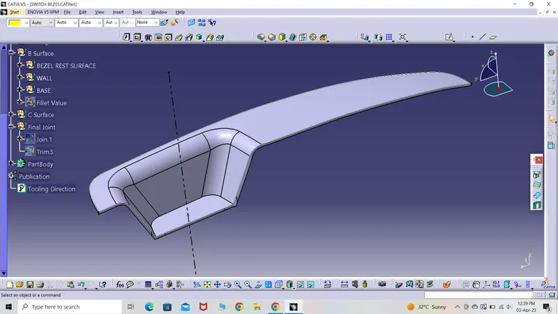
*) The tooling axis is indicated by a dotted black line.
DESIGN CONSIDERATION:-
- Class – A surface should be aesthetically smooth and good.
- Class – B surface should have all the supporting features like ribs.
- Parting Line should coincide with the B surface since flashing couldn’t affect the aesthetic of Class – A.
- Class – C surface should also pass the draft analysis.
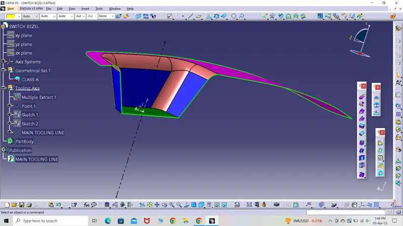
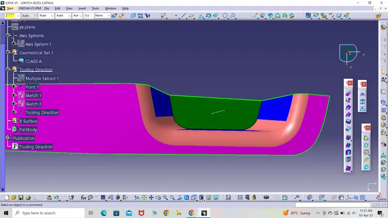
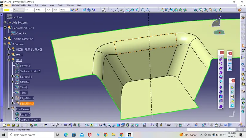
*) The top, side, and bottom surfaces were extracted from a new geometrical set called B surface.
*) The same surfaces were left untrimmed and then extrapolated to perfectly execute the trim instruction in between them.
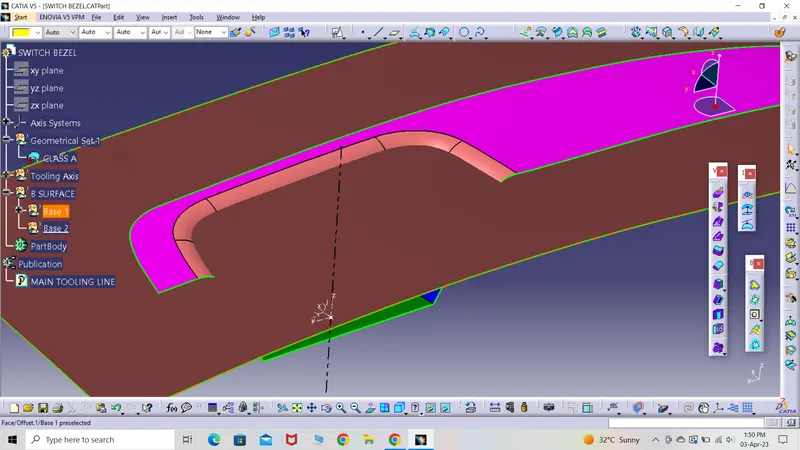
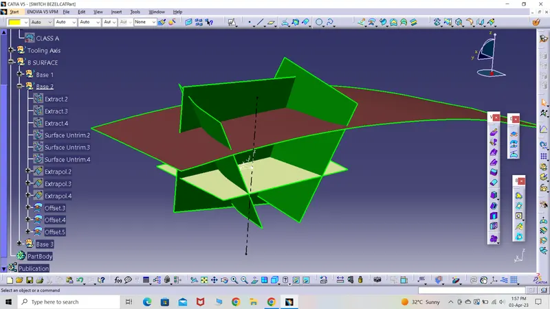
*) Once the surfaces were obtained, they were cut into one surface and trimmed.
*) The fillet radius was calculated by taking the same measurements and then applying them to the B surface in the same location as the A surface. The radius-thickness combination of 15-2.5=12.5mm and 14-2.5=11.5mm was specified as the fillet value.
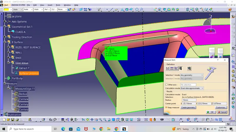
*) A new geometrical set, C surface, was constructed.
*) Using the multi-extract command, the boundary was drawn on the A and B surfaces.
*) It was turned into a surface using the swept option, with the tooling axis and draught angle set to 3 degrees.
*) Because the surface had too many marks, the smooth curve command was selected and substituted by the aforementioned curve to create a smooth surface with no marks.
*) Surfaces A and C were linked by setting the merging distance to 0.003mm.
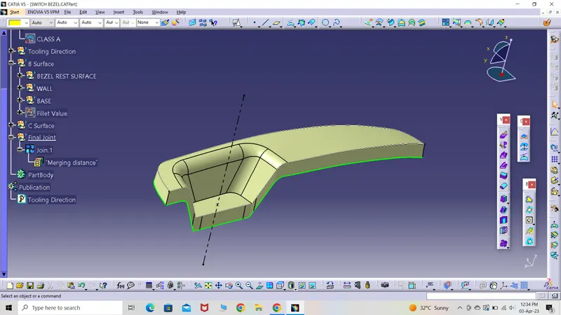
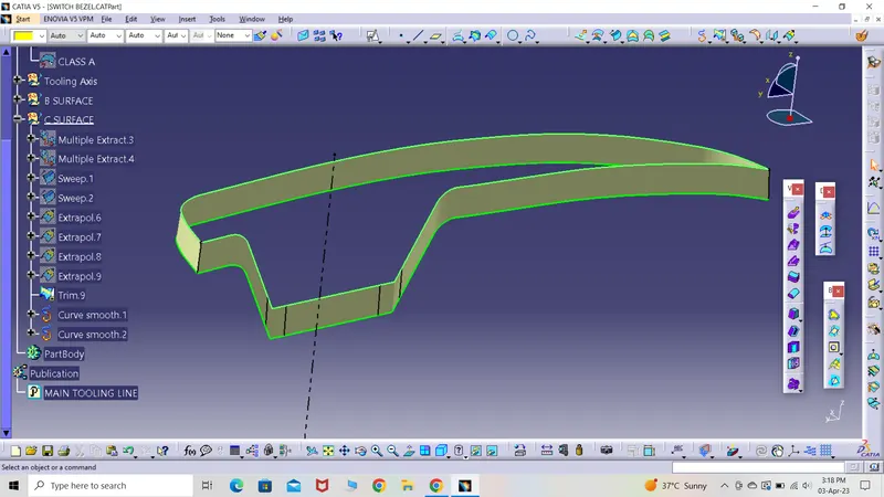
* The final geometric set, called Final join, was produced. Surfaces A and C were combined to create a single surface, and surface B was similarly trimmed while taking the previously described surface into consideration to create the final portion.
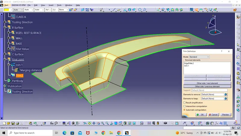
* The window was changed to part design, where the closed surface command was used to convert the hollow component into a solid part.
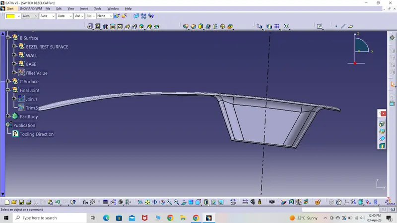
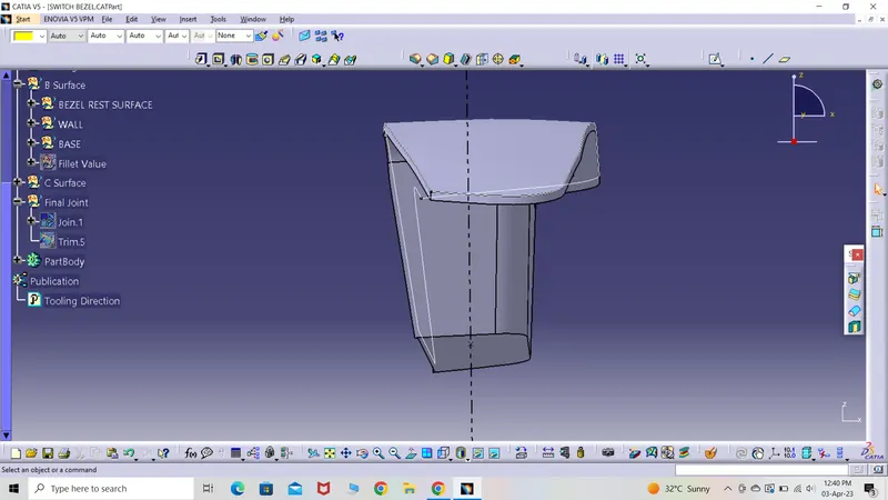
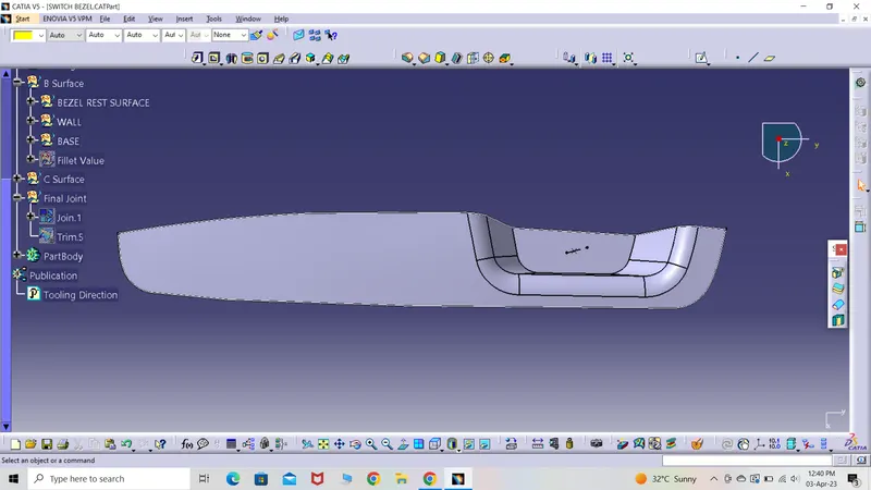
* Below, many perspectives of the same component are displayed.
ISOMETRIC VIEW
FRONT VIEW
SIDE VIEW
TOP VIEW
DRAFT ANALYSIS
*) The draught analysis was completed by moving to material view.
*) The compass was moved to the new location by aligning it with the tooling axis and locking it in place.
*) The result was obtained by placing the pointer on the part that displayed a red cross and clicking on the same position.
*) A location with a value less than 3 degrees was highlighted in red.
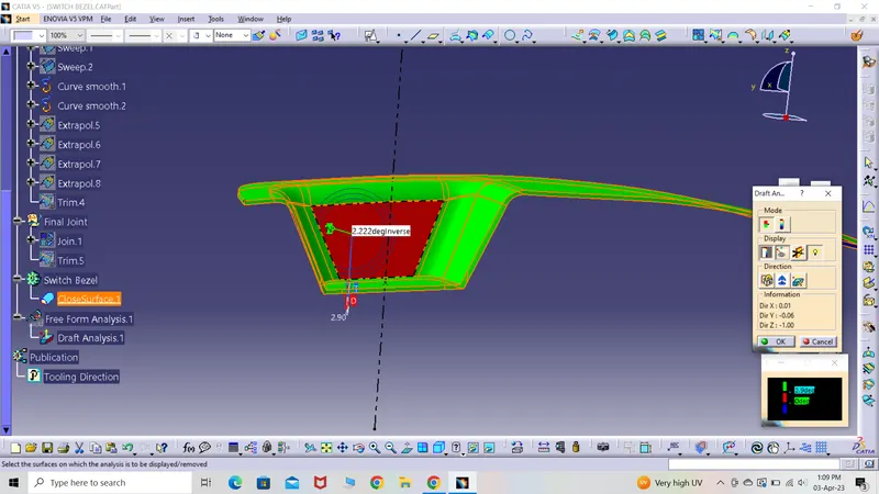
*) The value was changed to 2.9degree and the part turned green which states that the part is tolerable and producible.
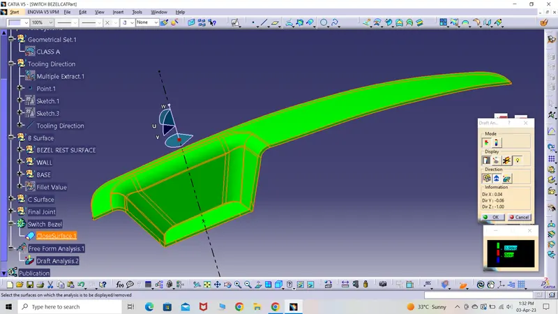
*) For more details, the .catpart file is attached below.