Week- 8 - Solid meshing
OBJECTIVE: To check for the geometrical errors and mesh the given Rear view mirror component, with the given 2D element Quality criterias given below.
|
S.No |
Quality Criteria |
Value |
|
1 |
Target/Average length |
1 |
|
2 |
Minimum Length |
0.5 |
|
3 |
Maximum Length |
2 |
Also, use the tetra elements to mesh the Volumes defined in the model and check for the below quality after Volume meshing.
|
S.No |
Quality Criteria |
Value |
|
1 |
Tet collapse |
0.2 |
REAR VIEW MIRROR:
fig 1
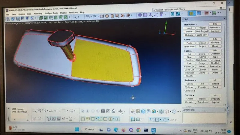
OBJECTIVE: To check for the geometrical errors and mesh the given Rear view mirror component, with the given 2D element Quality criterias given below. S.No Quality Criteria Value 1 Target/Average length 1 2 Minimum Length 0.5 3 Maximum Length 2 Also, use the tetra…
PROCEDURE: To solve the above objective we will follow 4 major steps as discussed below:
- Performing geometry cleanup & geometry check.
- Assigning Quality criteria and generating surface mesh.
- Defining a volume for the model components.
- Meshing the volumes with "Tetra rapid" algorithm & solving off elements with given quality criteria.
1] Geometry cleanup & geometry check:
The first step involves importing the geometry into the 'Ansa' tool and perform a geometry check. This is followed by the geometry cleanup which involves hiding of unnecessary 'cons' and checking if the distance between 'cons' is more than the minimum element size. This is shown below in the fig.1.
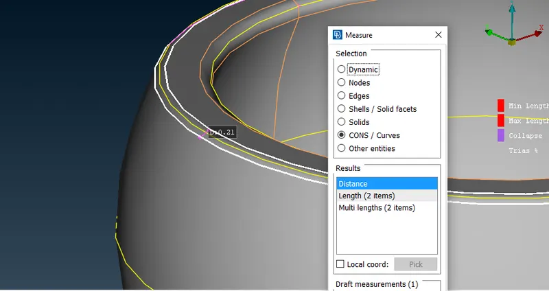
Fig.1.0
In the above fig.1, it can be seen that the distance between the 'fillet cons' is 0.21 which is less than the minimum element size (0.5), hence a mid curve is generated and projected onto fillet and the 'cons' that are capturing the fillet are suppressed. This is necessary inorder to pass the elements for the quality criteria.
2] Assigning Quality criteria and generating surface mesh:
The next step involves assigning the quality criteria and the mesh length given above. This can be seen in the fig.2 below.
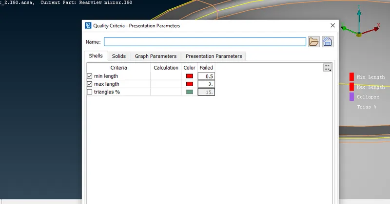
Fig.2
This is followed by surface meshing. To perform surface meshing we will mesh the curved areas using 'ortho-tria' mesh elements by spot meshing and the plane areas can be meshed using the normal 'tria' elements. The components of the geometry can be meshed seperately.
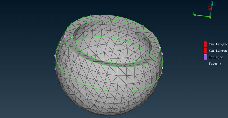 Fig.3
Fig.3
In the above fig.3, it can be seen that one of the components of the given geometry has been meshed using 'ortho-tria' elements. Also, if any of the elements fail for the defined quality criteria, reconstruction of mesh can be done untill all the elements pass the quality criteria.
3] Defining a volume for the model components:
When all the components of the model geometry are meshed and all the elements are checked for the quality criteria, we define a volume for each of the surface meshed components in the 'volume deck' of the ansa tool as shown in the figure below.
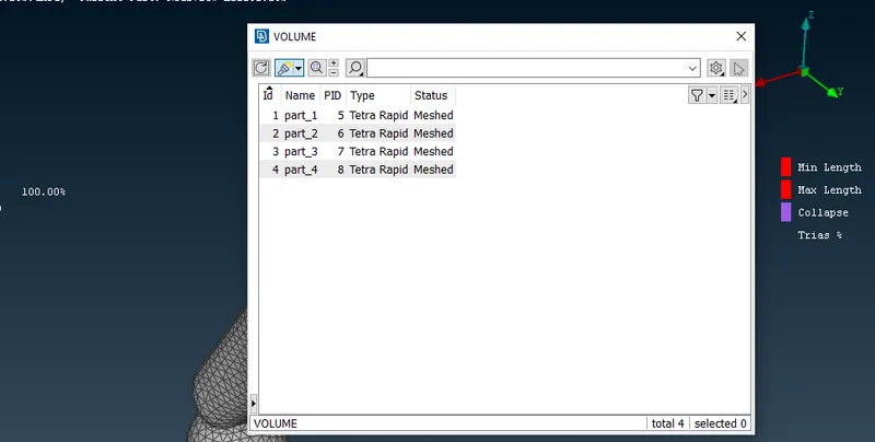
Fig.4
4] Meshing the volumes with "Tetra rapid" algorithm & solving off elements with given quality criteria:
This involves meshing the defined volumes with either the 'tetra rapid' or 'tetra FEM' algorithms. The tetra meshed volumes of the model can be seen in the below figures.
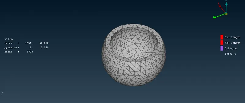
Fig.5
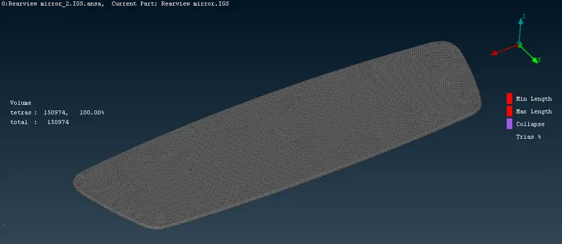
Fig.6
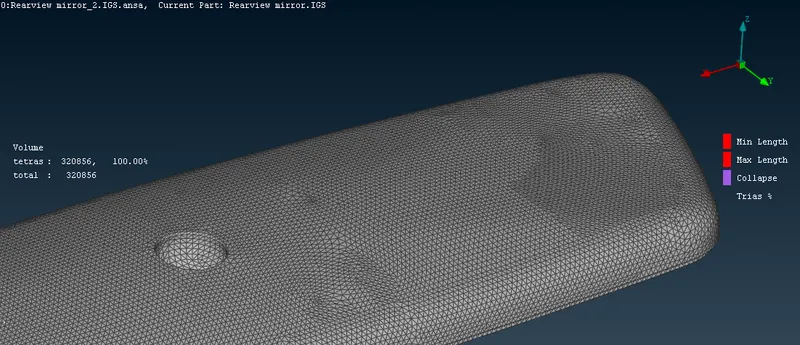
Fig.7
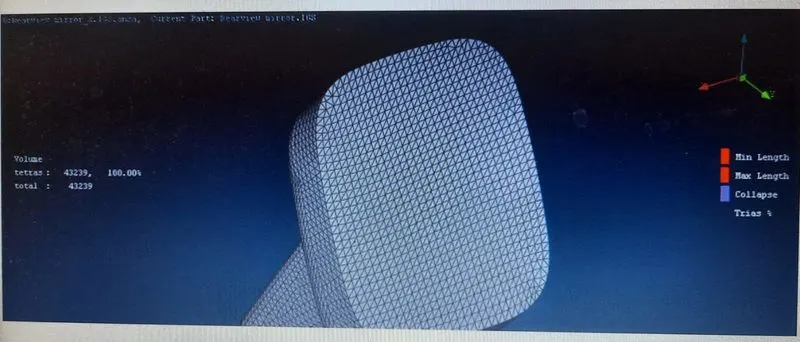
Fig.8
The final step involves fixing the off elements if present and resolving kinks and raised edges. The off elements in case of the volume mesh will be the elements failing for the 'tet collapse' criteria. This can be either solved by auto correction using 'improve > fix quality' or can be manually corrected using 'grids > MV free'.
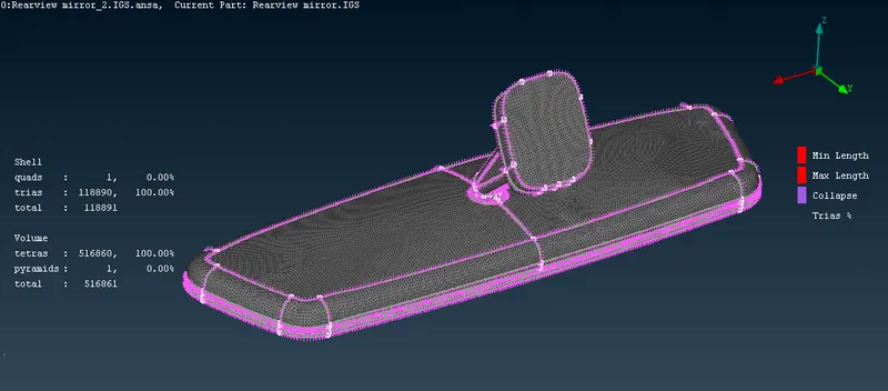
The final solid meshed model can be seen in the figure 9 below.
fig 9
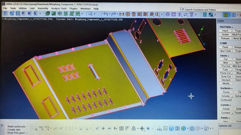
Sheet metal component:
fig 10
 starts morphing:
- The geometry clean-up and morphing operation are carried out as mention in the above procedure.
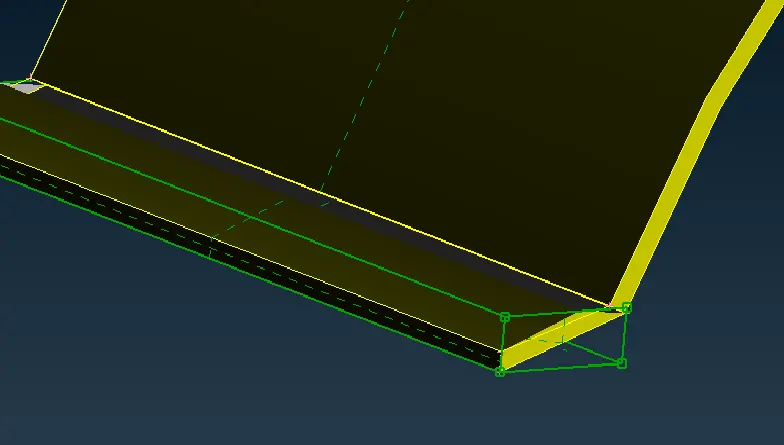
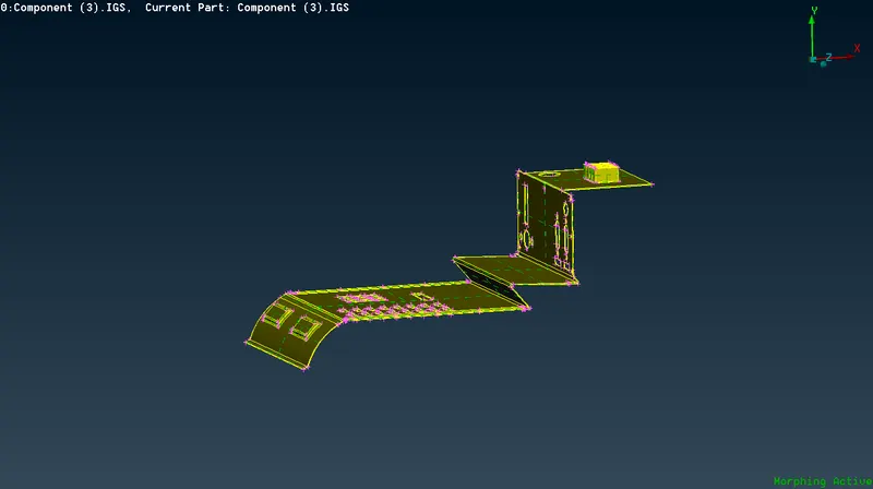
- The images below represent the morphing operation carried in the sheet metal component.
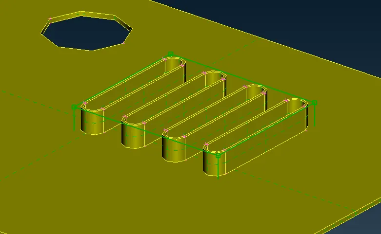
- 10 Before morphing 11 After morphing
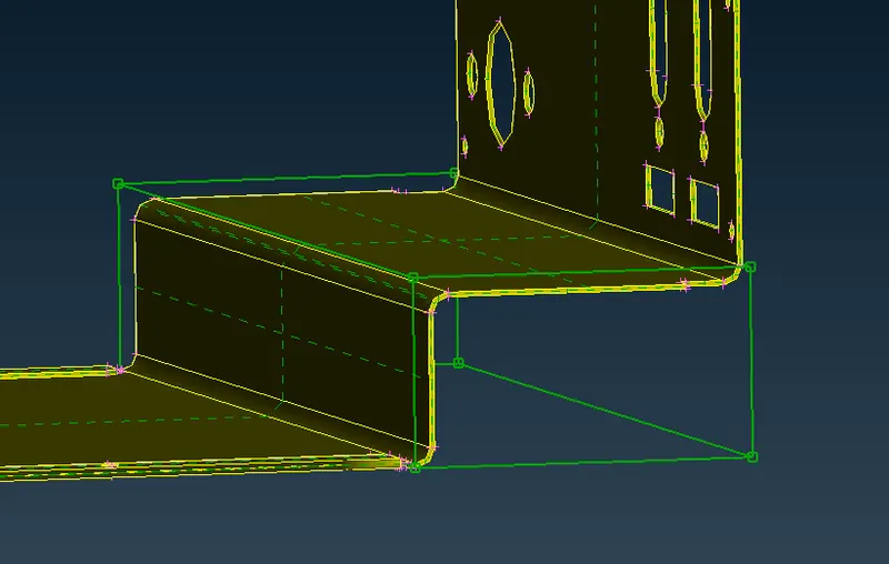
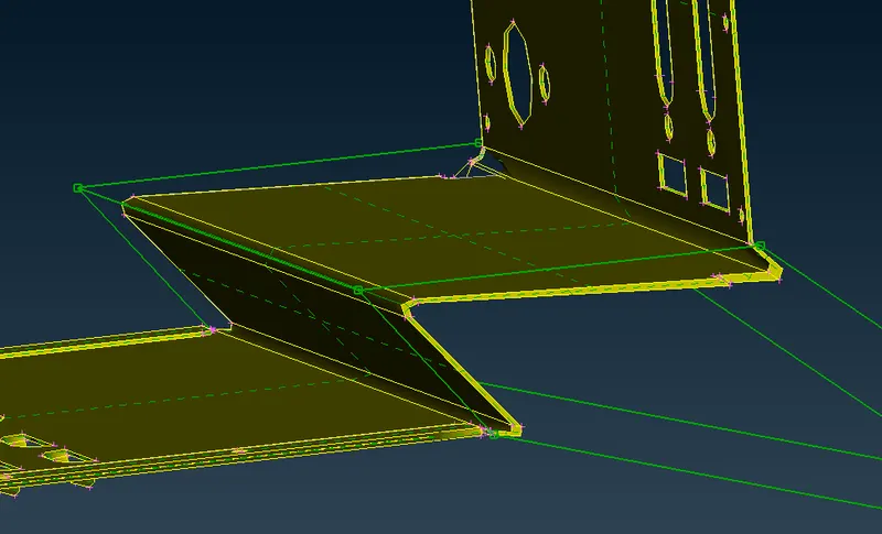
- 10.1. Before morphing 10.2. After morphing
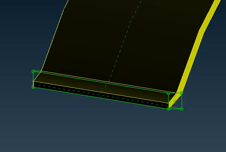
- 11.1. Before morphing 11.2. After morphing
- 12. Before morphing
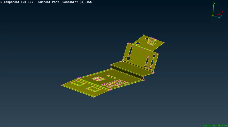
- 12. After morphing
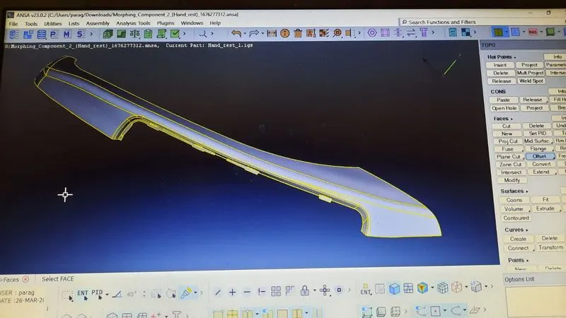
- Finally, saved the file.
-
OBJECTIVE:
-
The main aim of this project is to perform the basic morphing technique for a Hand rest plastic component and a sheet metal component.
-
PROCEDURE:
Hand rest plastic component:
- Imported the given .stp file in the ANSA work page.
- Checked for the orientation i,e. the upper part of the model should be in gray color meaning positive and the lower part in yellow color meaning negative.
- The issues with orientation are cleared using the topo module-->faces-->topo.
- The resolution of the CONS is improved using Auxiliaries--> fine from topo module or perimeters-->length from mesh module.
- The model is then subjected to a geometry checkup to check any free edges between the models, duplicate surface, irrelevant CONS using the option tools--> checks-->geometry.
- Some geometrical errors are cleared using the Auto fix option and some are manually done using options like release hot points, release cons, topo, faces cut, etc. from the Topo module.
- Morphing is performed using the morph module.
- when the morph module has selected the activation for morphing is done as shown below,
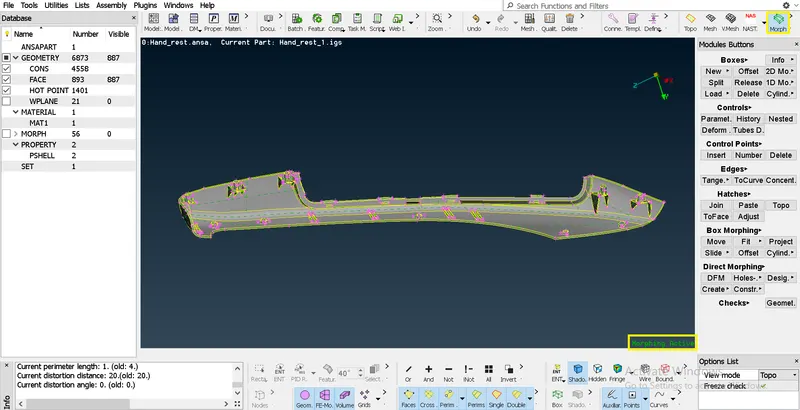
- 13.1 Morph activation
- The region that has to be morphed can be selected by using Boxes-->New-->ortho option, and Morph box representation is created as shown below,
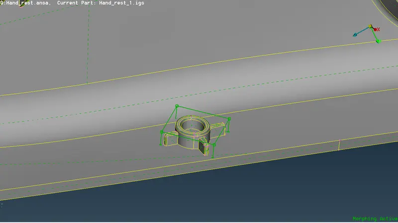
- 13.2 Morph box representation
- This morph box can be controlled by using the control grids at each end, the control grids can be moved manually or by specifying the distance.
- To move the control grids, Box morphing-->move option is used, on clicking the option a dialog box opens to selects the grids as shown below,
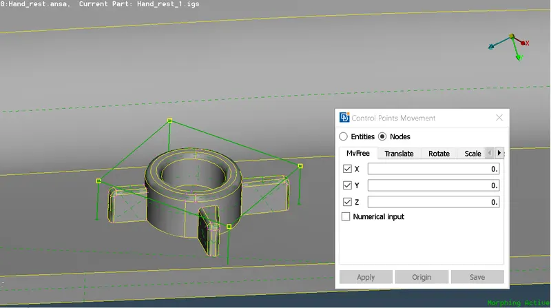
- 13.3 Selection of grids
- The movement of the grids can be done either using the global coordinate system or a local coordinate system.
- In order to move the grids using a local ordinate system, right-click is done inside the morph box to get the local coordinate as shown below,
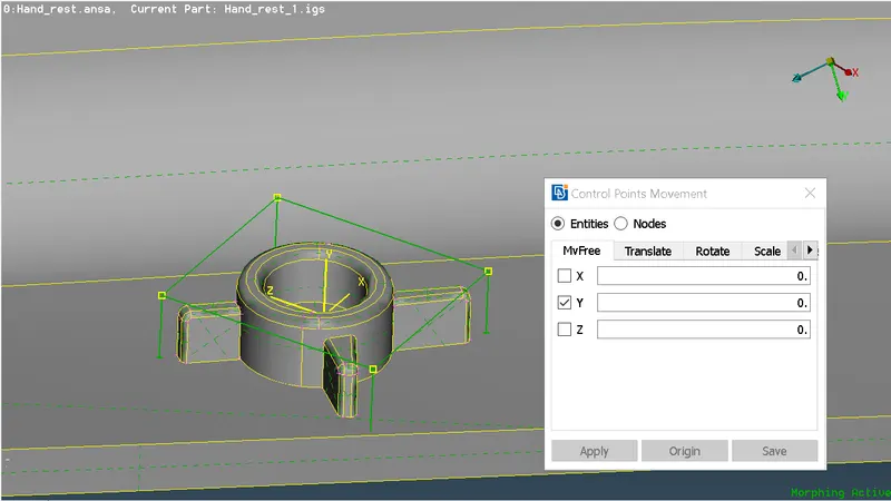
- 13.4 local coordinate representation
- The movement of the grids can be constrained in a particular direction by ticking the coordinate system direction as shown above in the picture.
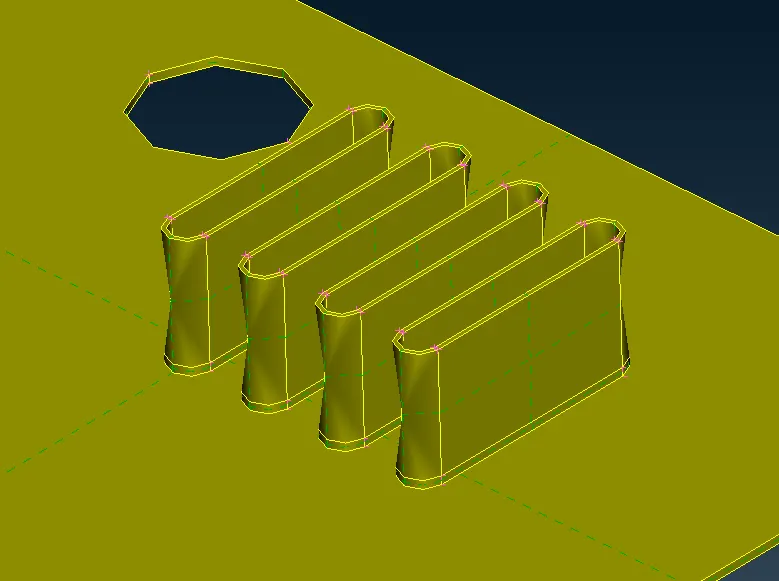
- In this hand rest component, the morphing operation is carried out by increasing the height of the dog houses and ribs as shown below,
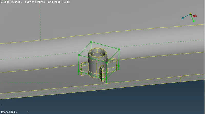
- 13.5 Before morphing 13.6 After morphing
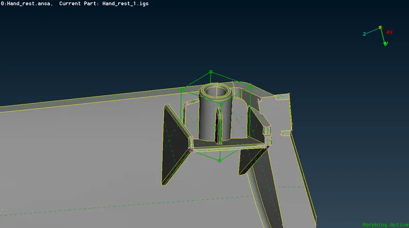
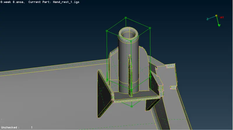
- 13.7 Before morphing 13.8 After morphing
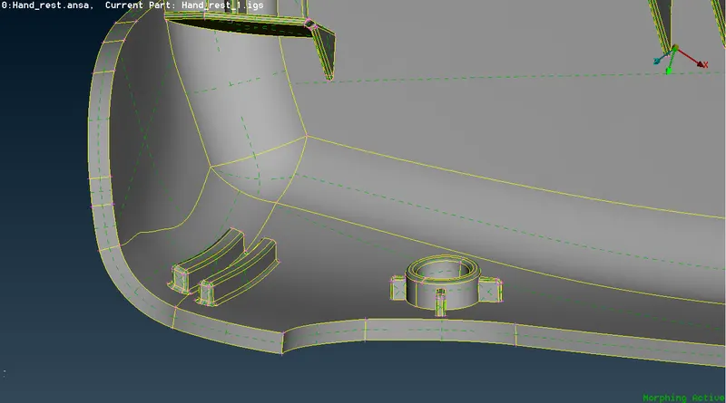
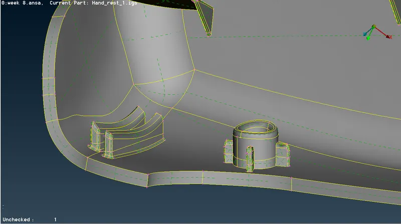
- 13.9 Before morphing 13.10 After morphing
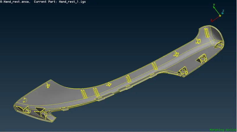
- 14.Model before Morphing
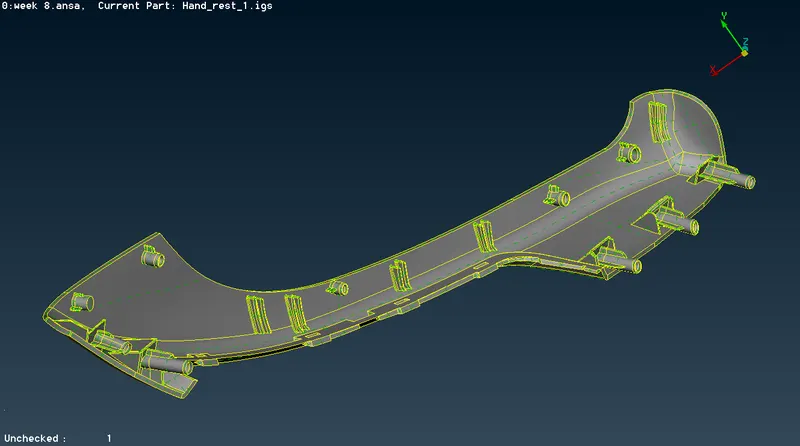
- 14.1 Model after morphing
-
INDUSTRIAL APPLICATION:
- The automobile industries like Honda, Maruthi Suzuki applied this morphing technique in designing a new model car from their existing models.
- For example, the Honda Brio is a Hatchback car from that model Honda creates its sedan version Honda Amaze.
- The morphing technique not only used for developing the car models but is also used to change the shape after the simulation of the FE model.
- For example, In a FE model, if the stress concentration is higher in a particular region, it can be reshaped by using this technique for better results.
RESULT:
Hence, the basic morphing operation is done for the Hand rest plastic component and a sheet metal component.