Week 12- Final project
*Introduction-
*Door Trim Panel
The door panel connects the interior of the car and the machinery inside the door, as well as the passengers inside the car and the door. They must comply with a number of operational, aesthetic, and safety design specifications. They should also preserve the material theme of the dashboard while concealing the electrical and mechanical components that operate the car's locks, windows, and other luxuries. The door panel has changed from a simple latch and winding mechanism in two parts to a more sophisticated enclosure. Currently, doors have a central locking mechanism, an inside full-width panel with speakers, and electronic glass. These panels often contain a core made of foam that is covered in fabric or plastic. Plastics are important.
*Class-A surface-
The Course-A surface is the most visually appealing surface of a plastic component. As an input component for design work, it is also the surface that the designer creates aesthetically.
*Class-B surface-
The Class-B finish is a high-quality, flaw-free finish. A Class-B finish is the most common finish for outdoor surfaces. It is commonly specified on elements and surfaces that are visible, such as exterior coverings and panels.
*Class-C surface-
The Class-C finish allows more defects than Class-A or Class-B finishes do. Interior surfaces that are difficult to view, sections that will be covered by another part when the component is finished, or surfaces that the customer feels don't need a high level of aesthetic finish typically have Class-C standards created for them.
*Tooling Axis-
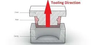
When molding, a machine configuration is offered to open the mold in the direction of the tooling. Alternately stated. The Core and Cavity are two separate components that make up the mold, and how they separate depends largely on the tooling orientation.
*Draft Analysis-
Using the Draught Analysis tool, you may decide whether the section you sketched will be easy to remove. This type of analysis, based on color ranges, locates locations on the studied element where deviations from the draught direction at any given point match predefined values. The majority of parts or applications require a minimum of 1/2 to 1 degree, with 3 degrees being considered the industry standard.

1) Creation of tooling axis:-
To determine the tooling axis, the model must be imported into catia as a product.
MASTER SECTION FORMULATION.file=>open, browse igs file.
Given class A surface
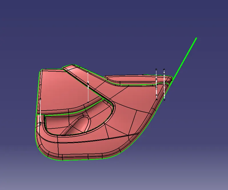
The rear side of class A with the master section
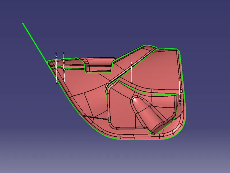
After creating a product file, duplicate each component into a new part file and give it the proper file name.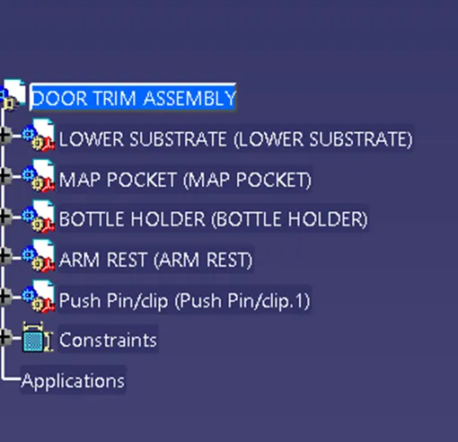
*CREATION OF TOOLING AXIS
In the first stage, insert a geometric set. Extract the base surface and make a point in the center of it with the point tool's point-on-the-surface option. Find a suitable axis to create to guarantee that all faces are clear for tooling.
Step 2: Create an axis system without using the preceding option. Create a positioned sketch with the axis system's zy plane as a reference point and the point above as a reference point.
Step 3: Select an appropriate plane (zy) and utilize the intersect 3d objects option in the project tools to create two lines. Draw two lines that intersect at the projection point, as well as lines on either side of it. To draw a line, use the bisect option. Align
Step 4: Draw the tooling axis about the x-direction using the projection point as the beginning point and the xz plane as the reference plane in a position drawing. Create an intersection by using the projection tool and the cut section tool. Draw a line that touches this line after that.
Step 5: Draw a horizontal line with a maximum 5-degree angle from the starting position. Use the bisect option to draw a line that connects the lines above. This is our X tooling axis.
Step 6: Create a new line between the X and Y tooling lines by using the bisect option. This is the Tooling Axis that is required for us. Create a website for this and call it the "tooling axis."
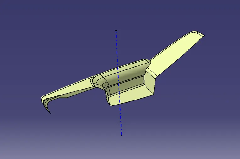
PROCEDURE FOR DRAFT ANALYSIS:
1) When the tooling axis and component have been developed, use the Publication from tool option to publish them.
2) From the Inserts toolbar, select the Feature Draught Analysis tool.
3) After altering the view choice to your liking, select the material option under shading.
4) After aligning it with the tooling axis, pick the axis option from the Draught analysis tools, and then lock it.
5) Increase the draught angle value to 3. Select Quick Analysis Mode to display the feature in the colour scheme supplied. Check that the draught analysis is clear from every angle.
6) Since the generated tooling axis does not remove the draught analysis at the formed axis, click the lock axis button to unlock it. To rotate the tooling axis, left-click on the rounded top of the axis system. Rotate the axis up until the maximum clearance is reached. Right-click the axis and choose to lock it after that.
7) Using the initial axis origin and this axis, create a line using the point and direction (using compass direction) option. We require the tooling axis in question.
8) If we now perform a draught study on the ribbed area, we can see that it has not yet been eliminated. We must therefore create a side-core tooling axis. Make a line utilizing
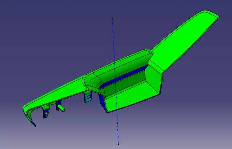
Similarly created a tooling axis using the same procedures for all other components.
*Tooling axis for lower substrate-
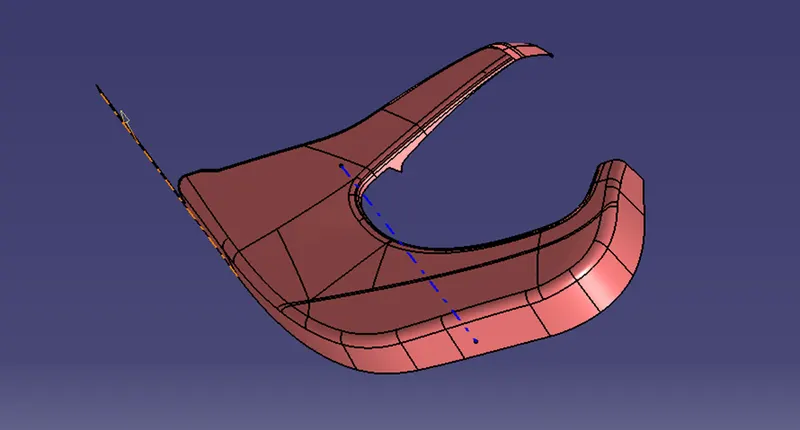
*Tooling axis for Map pocket-
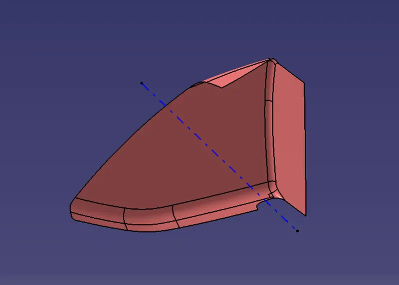
*Tooling axis for BOTTLE HOLDER-
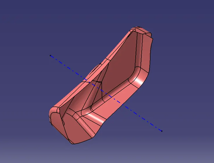
In this view, we can see that the CYAN color patches have a 0-degree draught angle. This could lead to ejection concerns during the molding process. As a result, the class A surface must be modified to meet the draught criteria. As a result, tooling axes for each component have been constructed.
2) Creation of class B surface-
Create a class B surface using this method for the lower substrate.
Step 1: Use the offset tool with a distance setting of 2.5mm to create an offset for a class A surface.
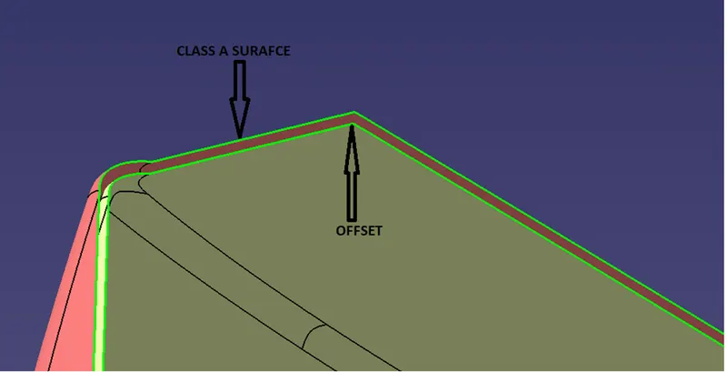
Step 2: After offsetting, the edges of this surface were all expanded with the extrapolation tool. This is done to ensure that the dividing line reaches the B surface.
Step 3: In places where extrapolation was not possible (Fillet or cusped surfaces), the multi-section surface option was used.
Step 4: Join every extrapolated surface and multisection surface to form a single surface.
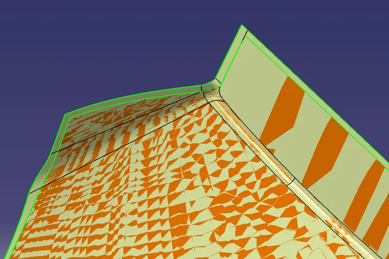
Similarly, a class B surface was created for other components.
*Class B surface of ARMREST-
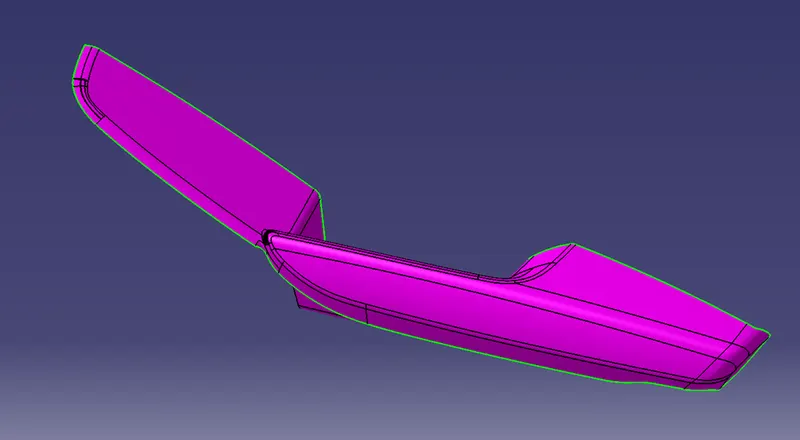
*Class B surface of LOWER SUBSTRATE-
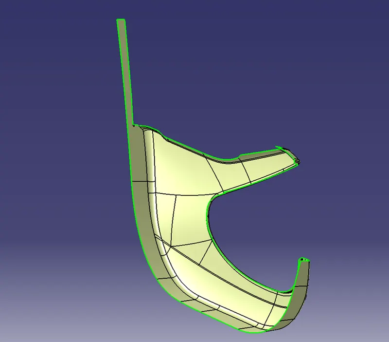
*Class B surface of BOTTLE HOLDER-
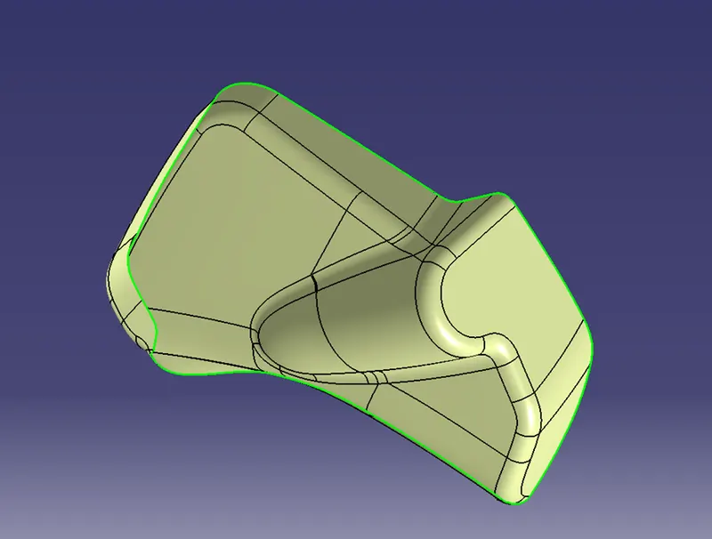
Hence class B surfaces for all components were created.
3) Creation of Class C surface-
creating a class C surface for the upper map pocket procedure
Step 1: Use the sweep command to create a new surface that is perpendicular to an existing surface. This angle is normally 90 degrees for mating surfaces and relies on the draught angle for free edges.
Step 2: In places where a sweep is impractical, create a new surface using a multi-section surface.
Step 3: To build the C surface, join all of the surfaces from Step 3.
As a result, MAP POCKET's class B surface was developed.
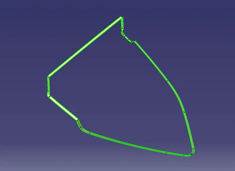
Hence C surface was obtained for MAP POCKET
Similarly, C surfaces were obtained for all other components.
Class C surface for ARM REST-
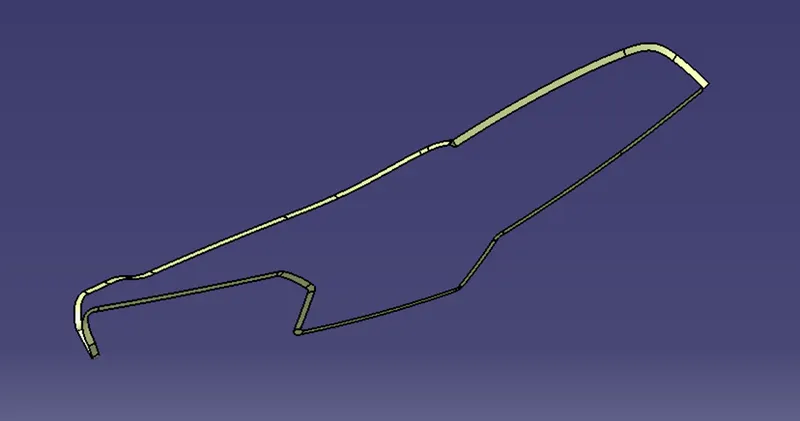
*Class C surface for LOWER SUBSTRATE-
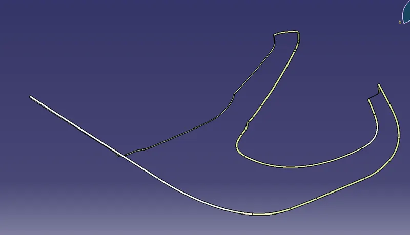
Hence class C was created for all components.
4)Creation of closed body-
How to make a closed body for the lower map pocket.
Step 1: To join Classes A and C, use the trim or join option.
Step 2: Using the trim feature, combine the aforementioned trim with class B.
As a result, we now have a closed body for the BOTTLE HOLDER.
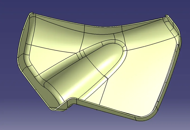
The similarly closed body was obtained for all other parts
Closed body for MAP POCKET-
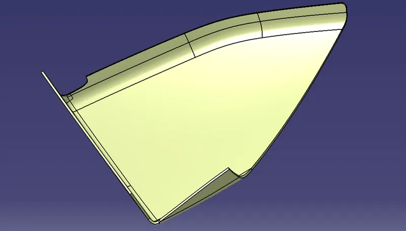
Closed body for LOWER SUBSTRATE-
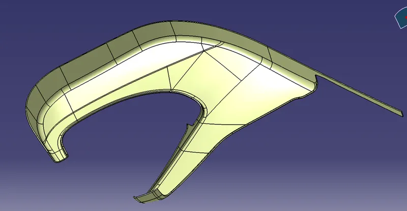
Closed body for ARM REST-
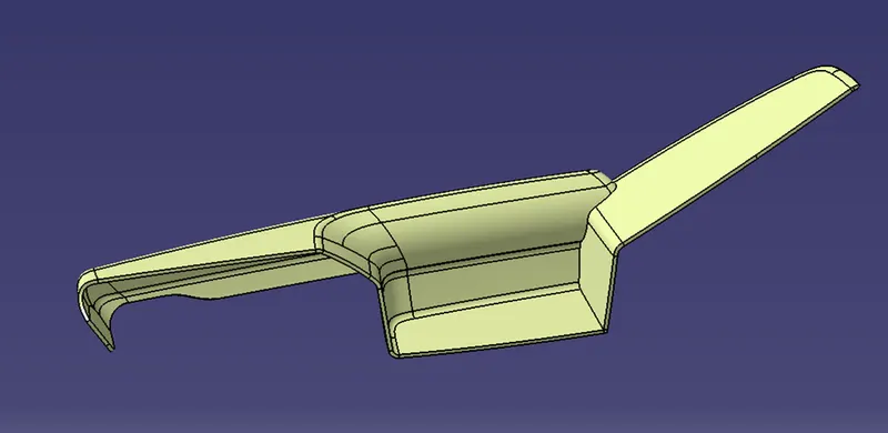
Hence, we have created closed bodies for all parts and thus we have created solid bodies from them.
5) Draft Analysis:
How to check the lower substrate's draught analysis.
1) Once the tooling axis and the component have been developed, publish them using the Publication from tool option.
2) From the Inserts toolbar, choose the Feature Draught Analysis tool.
3) Under Shading, choose the Material option, and then adjust the view choice to your liking.
4) Select the axis option from the Draught analysis tools, align it with the tooling axis, and then choose the lock option to lock it.
5) Increase the draught angle's value to 3. To display the feature using the suggested colour scheme, select Quick Analysis Mode. Make sure the draught analysis is accurate from every perspective. Click ok to exit the Draught analysis mode.
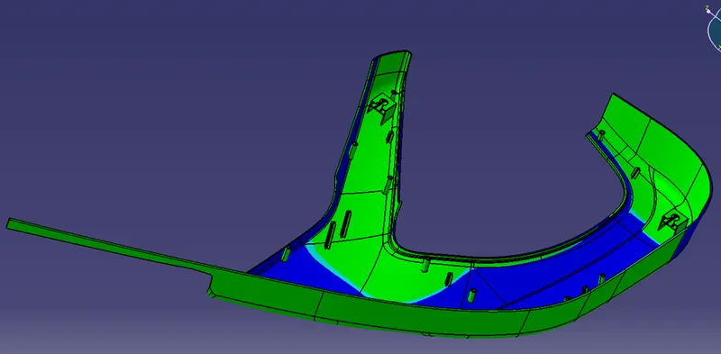
Draft analysis for MAP POCKET-
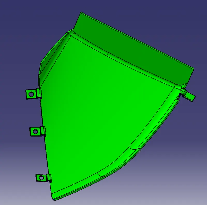
Draft Analysis for ARM REST
As a result, we completed the first phase of the project and received the closed body for all parts, clearing the draught analysis.
*PART 2-
Attachment of flanges using given master sections.
Procedure to create FLANGES and HEAR STAKES for Armrest from given master sections.
Step 1: Produce the necessary sweep and guide profiles for the flange top surface using a number of extracts.
Step 2: Using the sweep option, create a surface from the various extracts below.
Step 3: Using extrapolate to extend the surface in accordance with the master section, create a solid body in a new body. For the heat stake, create flat surfaces with holes.
Step 4: A master section point was used to pad a sketch in order to create a heat stake.
Step 5: Multiple extracts from the master region were thickened and cushioned to provide the stake support.
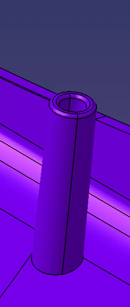
Similarly, features were created on all parts according to the master section.
Flanges on MAP POCKET-
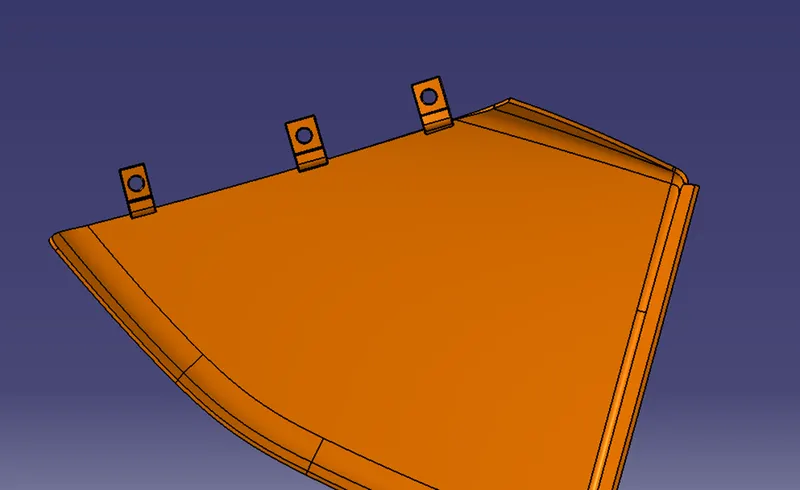
Hence, we have made features according to the master section.
3) Creation dog house and additional attachment features according to industry standards.
Procedure to create dog house on LOWER SUBSTRATE-
Step 1: Establish a point at the required place and a plan based on it. Draw a picture utilising the dog house as the focal point.
Step 2: Using this profile and the draught direction with a 1.5-degree draught angle, create a surface with the sweep tool.
Step 3: To create the required surfaces, extrapolate and extrude options are utilised. Trim and split options are then used to create the dog house's exterior shell.
Create a new body and give it the name "dog house" in step four. Use the thick surface option to create a solid with the specified thickness.
Step 5: Transform the dog home to the required height using the translate option, and use the thick command to enlarge the base surface such that
Step 6-Extract the inner base edge and build a surface to acquire the required base profile. Create a solid with a thick surface, then use a Boolean operator to remove it from the base of the dog home.
Step 7: Create a drawing, extrude it, and then split it from the solid to create the top profile for connecting push pins.
Step 8: Make a new drawing, extrude it, and offset it to make a base for the push pins to rest on. To convert it to solids, use the thick surface option.
Use Boolean operation union trim to obtain the required design.
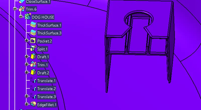
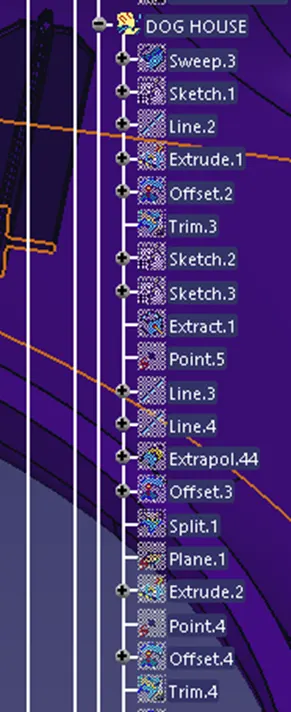
Thus, we have created a dog house.
Now we have made a complete dog house. Use the translate (point to point) option to position it in the required locations.
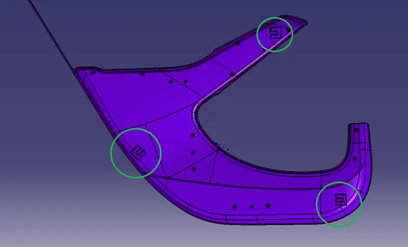
Using the methods indicated above, produce heat stakes and flanges where necessary to produce a full substrate body. Apply draught to all necessary surfaces and fillets to all edges that are straight.
Final MAP POCKET-
Final ARM REST-
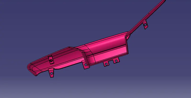
Final BOTTLE HOLDER-
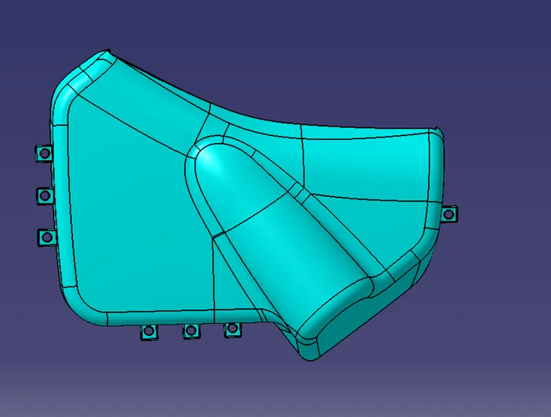
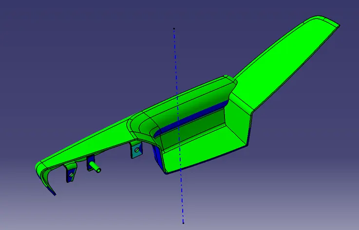
Draft analysis for Completed parts
1)ARM REST-
2) Lower Substrate-
3) MAP POCKET-
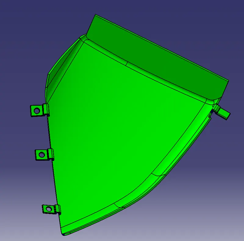
4)BOTTLE HOLDER-
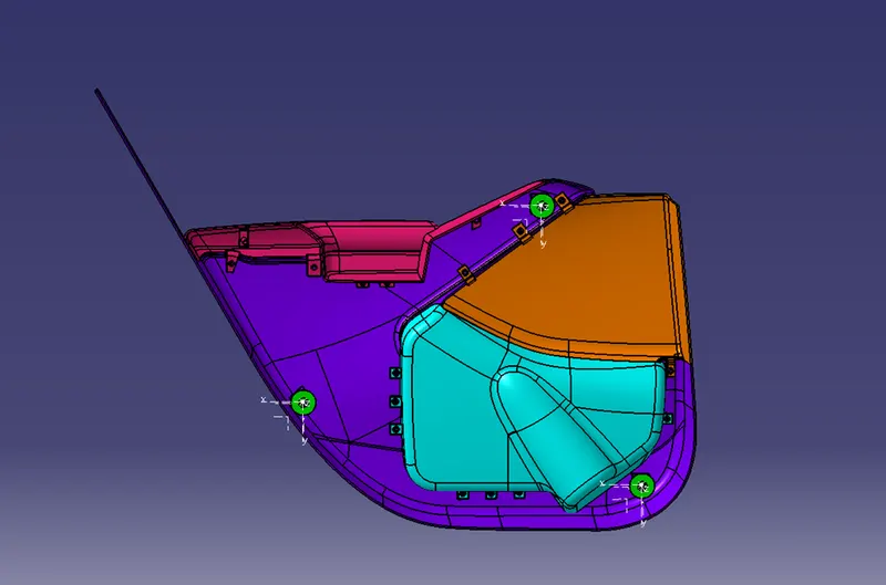
COMPLETED DOOR TRIM-
*CONCLUSION-
The following inputs are used to create the CAD model, just as they are in OEM and tier1 firms.