Hood design-Week 2
Front Hood Design: Buggati



AIM :
to create the car's hood using the dimensions and input for the outside panel.
Hood Introduction :
The movable cover above the engine of a car is referred to as the hood (North American English) or bonnet (Commonwealth English). On some mid-engine and some rear-engine vehicles, hoods can be opened to provide access to the engine compartment or trunk for maintenance and repairs.
A front-engine vehicle's engine is covered by a hinged cover known as a car hood, sometimes known as a bonnet in certain other countries. Its function is to make the engine accessible for upkeep and repair. Usually made of steel, car hoods can also occasionally be made of aluminum.

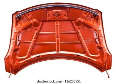
A hood is a cloth covering that covers the passenger compartment of a car (called as the "roof" or "top" in the United States). When opened and viewed from the front of many motor cars manufactured in the 1930s and 1940s, the resemblance to a genuine hood is evident; in newer vehicles, it still performs the same job, but no longer resembles a head covering.
The hood of a front-engined car may be hinged at either the front or rear edge, or it may be split into two portions, one on each side, each hinged along the centerline, as in the Ford Model T. Another variation merges the bonnet and wheel arches into a single piece, allowing the entire front bodywork to tilt forwards around a pivot towards the front of the vehicle.
Hoods are typically composed of the same material as the body. Steel, aluminum, fiberglass, or carbon fiber can all be used. To make the vehicle lighter, various aftermarket businesses provide fiberglass or carbon fiber steel hood replacements.
The inner hood latch/lock handle, a hood release cable, and a hood lock assembly normally make up the hood release mechanism, which is present in most cars. The hood lock handle is typically found in the door frame, close to the driver's seat, or beneath the steering wheel.
HOOD DESIGN :
Before the hood enters the hands of the designers, there are several other factors to be taken into account.
As the average height of a person varies from place to place, the height of the hood is created using national standards.
Additionally, a material consideration that can be produced affordably is necessary.
For pedestrian safety, the hood should be made of lightweight material so that if someone is hit by it, their injuries won't be severe.
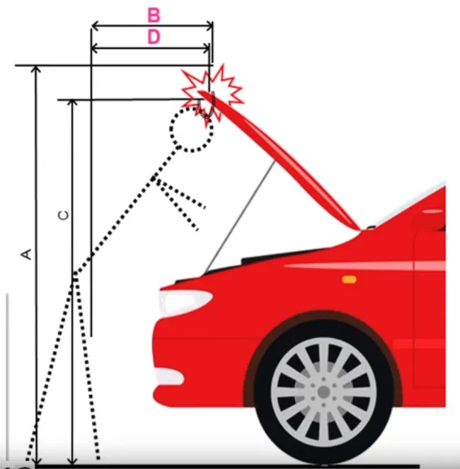
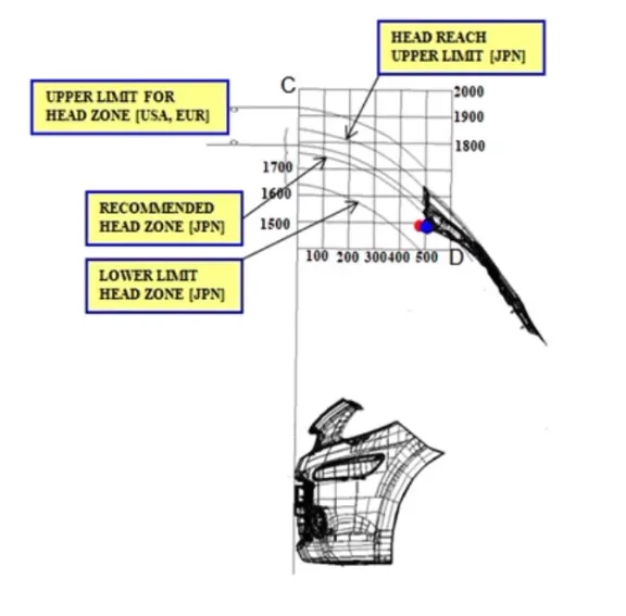
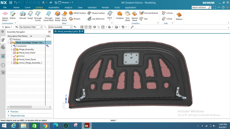
The input design for the input panel is given below :
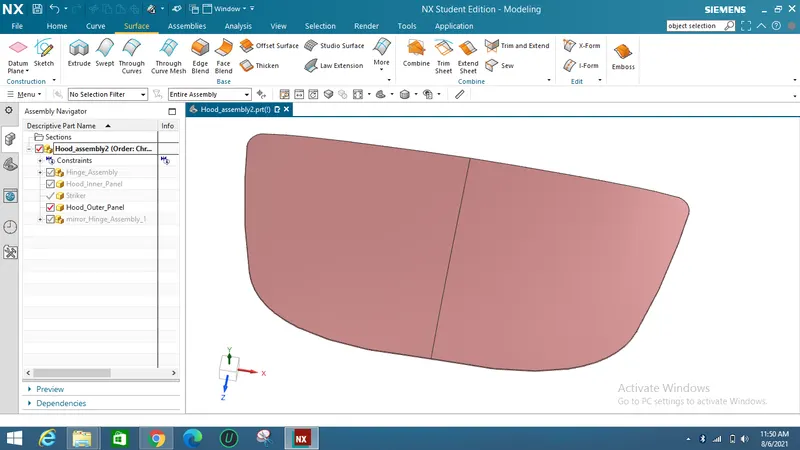
The outer panel given is shown below :
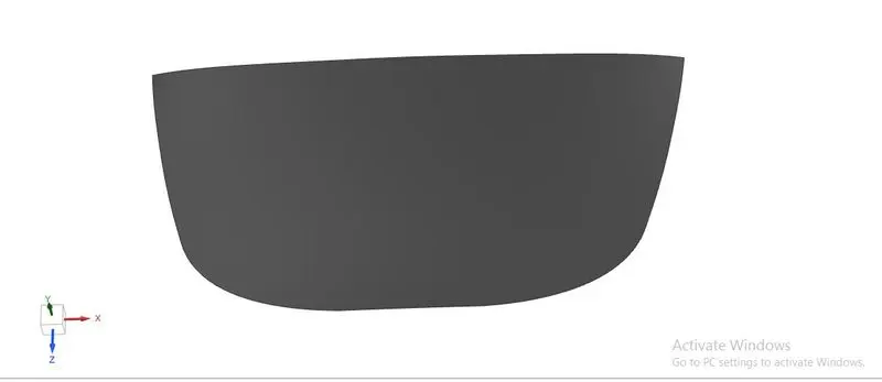
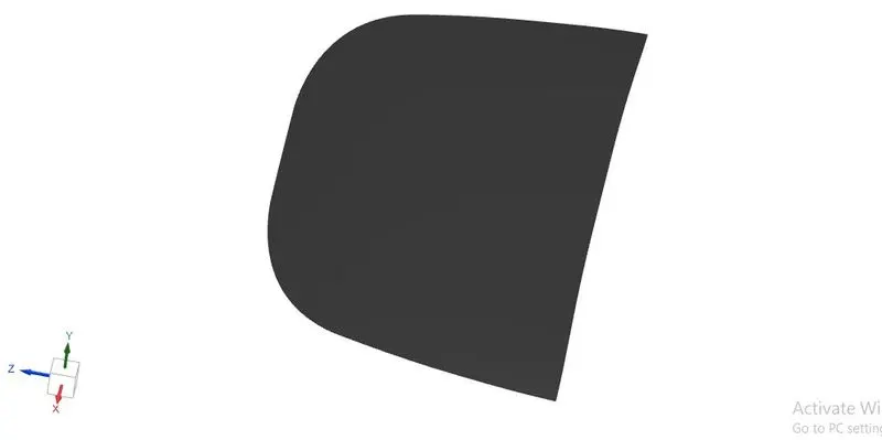
So according to the input design given the outer model should be modified to get the final input panel model.
First, the outer panel should be exactly halved into the middle using a midplane and should work on the half anel.
Then all the features should be mirrored and sewn together.
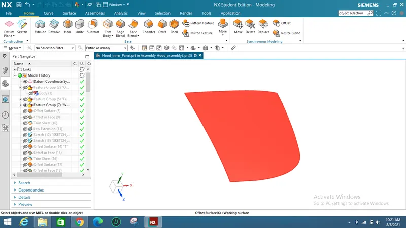
Now the features are to be built up like embosses, mastic points, embosses for hinges, and latch.
The law extension command is used to combine the upper edge and the offset surface.
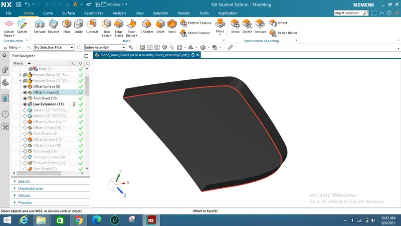
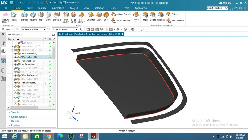
Through curves, command is used to join between the both upper face and the lower offset faces.
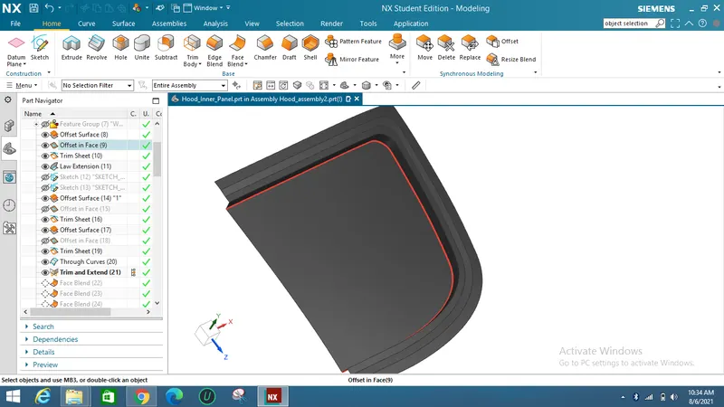
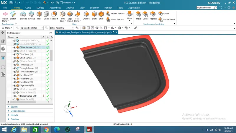
Now embosses should be created on the inner panel for removing material to get a lightweight component.
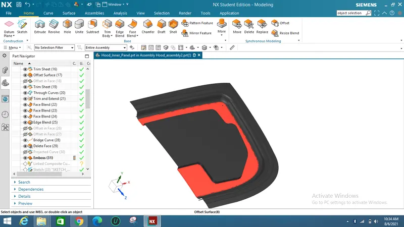
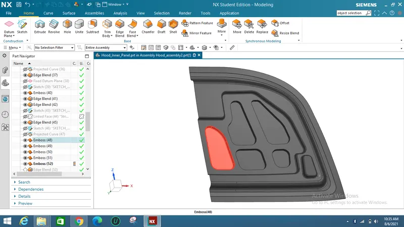
Below image is shown for mastic embosses and the hinge embosses.
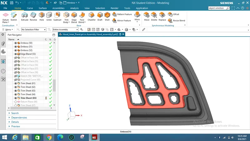
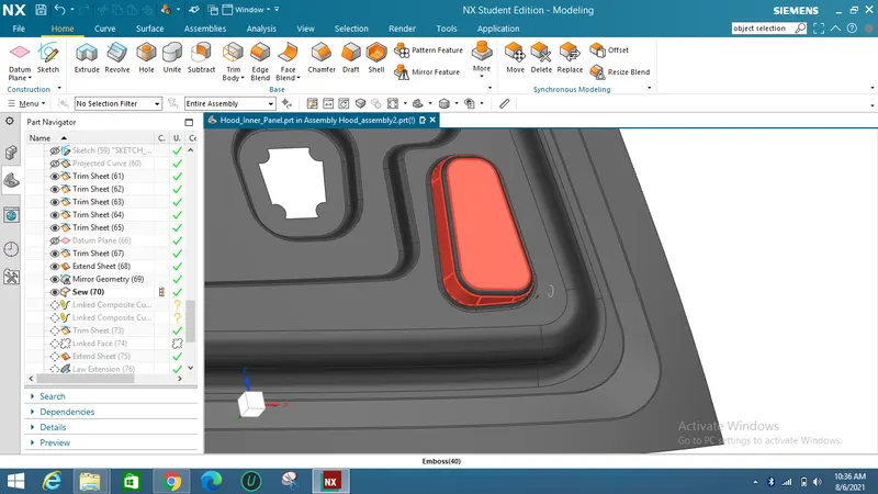
To stick the inner panel with the outer panel mastic points were created and the maximum distance between them should be 5mm.
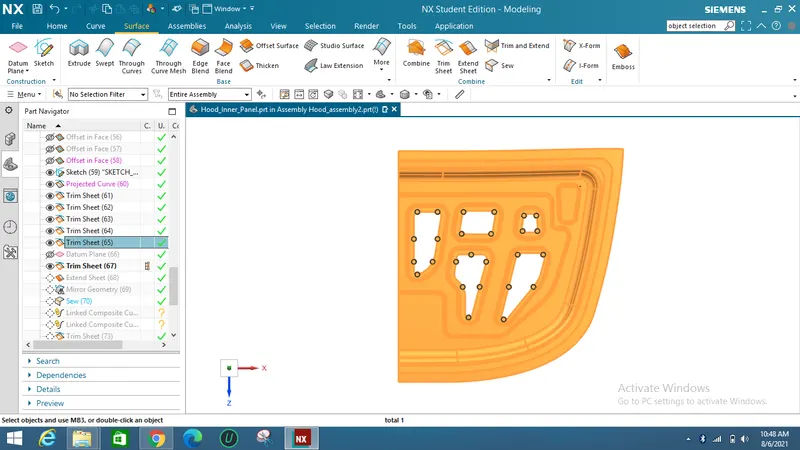
So after completing the mastic points the inner panel should be mirrored and sewed together.
Then the sewed feature should be examined with geometry to check if any cracks were built in between.
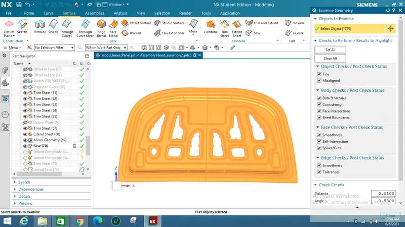
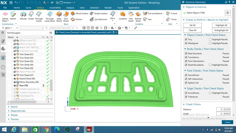
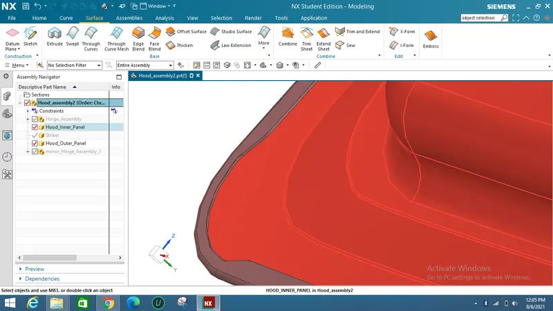
When geometry is checked, the green colour shows that there are no faults, whereas the red colour denotes the presence of errors in linking the mirrored section.
The ends of the embossed inner panel margins are where the hinges should now be joined.
HINGE PLACEMENT :
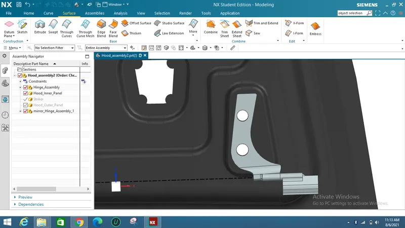
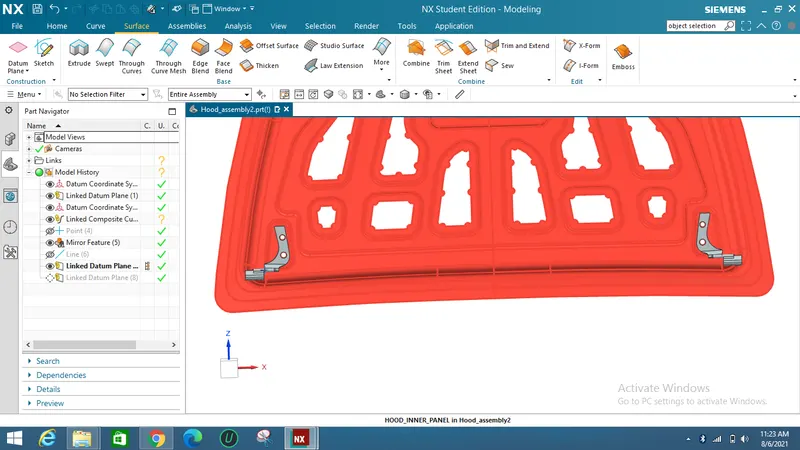
The hinges are first attached to the embosses, and as the inner panel is applied with a fixed constraint, a parallel and touch constraint is placed on the hinge.
In order to obtain the same hinge position on a different side of the inner panel, the hinge is then mirrored with an associative link to that side.
LATCH ATTACHMENT :
The latch/Striker is positioned from the basis of the hinges center point.
Two points are marked from the two hinge axis and a line is drawn from the two points.
A midpoint is taken from the line for positioning the latch.
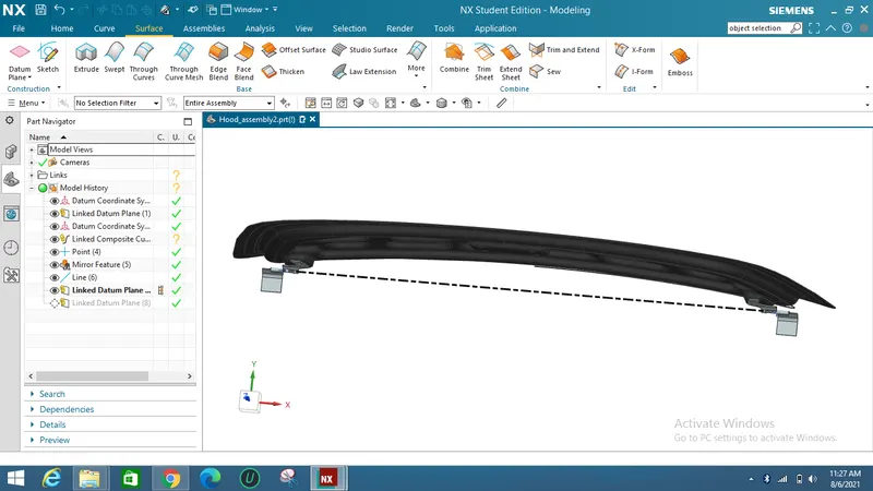
Now a circle is drawn as that point as a center with a radius of approximately 300 mm(based on the hood designer) and the tangent line is drawn on that circle.
Then latch coincides with that tangent line.
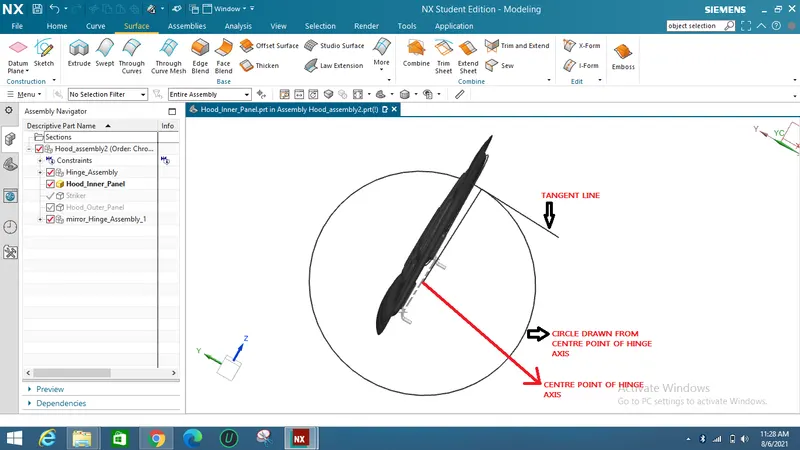
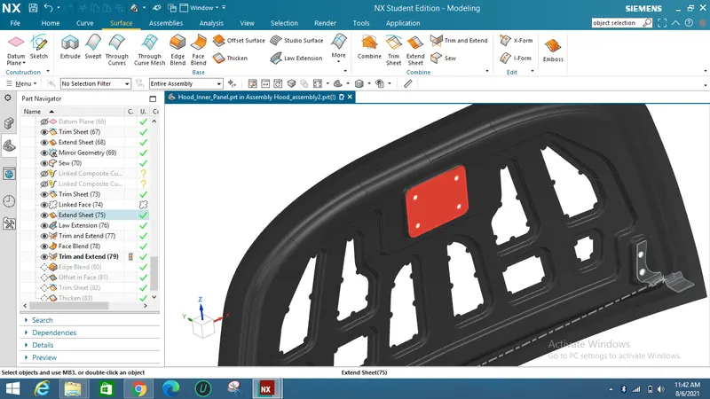
So after the latch position is fixed then the embossing is created from the latch surface using a wave geometry linker into the inner panel file.
Striker emboss is shown in the below image.
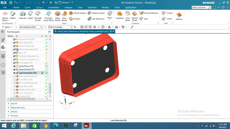
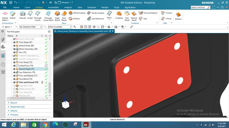
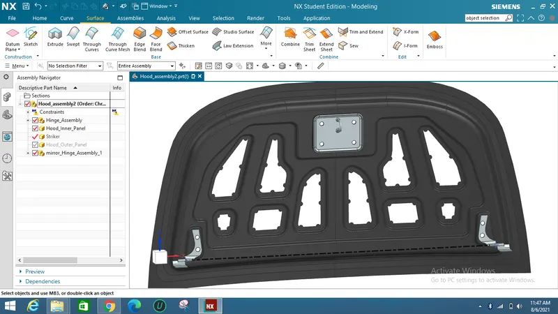
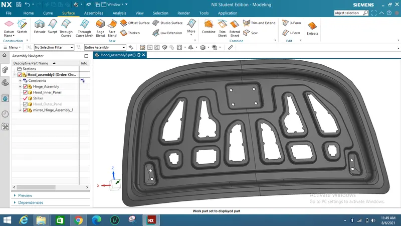
The whole assembly is shown below in the inner panel.
Hood Outer panel :
HEMMING OPERATION :
Hemming is a shaping technique in which the sheet's edges are folded or folded over another section to obtain a snug fit. Hemming procedures are typically used to join parts, improve the look of a part, and reinforce part edges.
Hemming is used in automotive component assembly as a supplementary procedure following deep drawing, trimming, and flanging to unite two sheet metal sections (outer and inner). Hoods, doors, trunk lids, and fenders are typical parts for this type of assembly.
Since the hemming operation has an impact on the surface's look and surface quality, precision is crucial. During the hemming process, material deformations might result in dimensional changes and other parts faults. The flange may split or crease, the material may overlap in the corner sections, or the material may roll in. Because of this, it's crucial to employ simulation tools to both better understand the hemming process and to drastically cut down on the quantity of "trial and error" cycles during test and production.
There are various types of hemming operations:
- Conventional die hemming
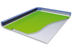
- Roll hemming
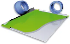
Conventional die hemming :
Die hemming by hand is appropriate for mass production. Die hemming involves folding the flange across the full length with a hemming tool. The actual hemming is usually the product of a forming process in which the flange is created using a hemming tool after the drawing and trimming operations are finished. Several production stages are required to hem the manufactured flange. These procedures include, for example, pre-hemming and final hemming depending on the flange's opening angle. Traditional die hemming production plants are relatively expensive, but the cycle periods are very short.
Roll hemming :
A hemming roller is used to hem rolls progressively. The flange is formed and the hemming roller is guided by an industrial robot. Several pre-hemming and final hemming process processes can also be separated into the roll hemming operation. When compared to traditional die hemming, roll hemming offers much greater tool flexibility and cheaper tool costs. The fact that the hemming is accomplished with a hemming roller that follows a predetermined path, however, results in substantially longer cycle times.
Corner reliefs are provided at the edges of hemmed part to provide corner reliefs.
Given outer panel data :
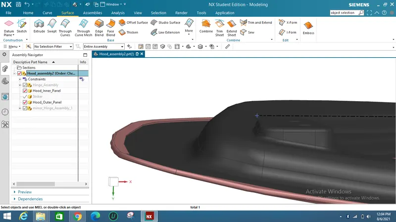
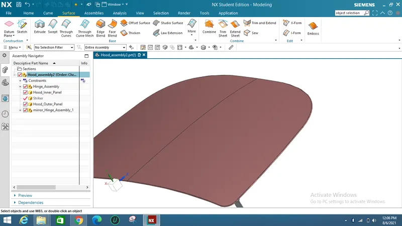
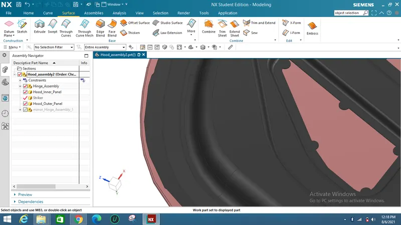
The outer panel is first offset to the distance below inner panel with all thickness and allowances are provided and using law extension command and face blend command hemming process is done.
FINAL HOOD MODEL DESIGN :