Week 9 - Challenge 3 - Bumper
BUMPER:
AIM: to make a model from the specified class-A surface.
INTRODUCTION:
CLASS-A SURFACE: A surface created by the designer and provided to the plastic modeler to work on. It is both an aesthetic and an outermost surface.
CLASS-B SURFACE: Class-B surfaces are those that are thinner than the class-A surface. This is the area of a model where the engineering components are located.
CLASS-C SURFACE: A class-C surface is one that connects class-A and class-B surfaces.
INPUT GIVEN:
A-Surface
The thickness of component is 3.00mm
- Draft angle is 3 degrees.
METHODOLOGY:
In this model we have focused on the following things:
Tooling axis
Draft analysis
Class-B surface
Class-C surface
Making a solid model from the surface.
The following tools were used to reach the final step:
Extract
Un-trim
Trim
Extrapolate
Offset
Edge fillet
Boundary
Sweep
Join
Close (part design)
CREATION OF TOOLING AXIS:
The tooling axis is the direction in which a mold's core or cavity opens. This axis is critical for determining component orientation in mould, core, and cavity design.
The inertia method is used to produce the tooling axis by following the procedures below.
Choose "Measure inertia" and the A-surface.
In the Measure Inertia window, click the "Create geometry" button.
Select Non-associative geometry in the Creation of Geometry window.
"Centre of Gravity" should be selected.
The point of inertia is formed.
The component is visible on all three axes, namely X, Y, and Z.
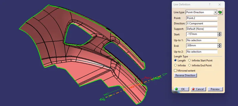
The X-axis is found to be the direction for the Tooling axis, and a line is produced using the CG point and the X-direction as the line's direction.
FOR DRAFT ANALYSIS:
We begin by analyzing the model and then select a dummy axis in the x and y directions.
We noticed that the side walls are not given any draught when we intersected to continue. As a result, we assume that the axis is normal to the bottom surface and parallel to the side walls. This will undoubtedly pose issues because a minimum draught must be given.
Because the class-A surface is created by another designer, only he has the authority to make changes, we examine it to finish the coin holder for practice.
Now we will insert analysis draught analysis and do the analysis as usual.
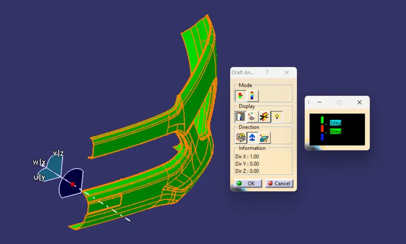
Align the compass and click on the surface; the model is predominantly red, as intended.
CHECKING THE INPUT - A SURFACE:
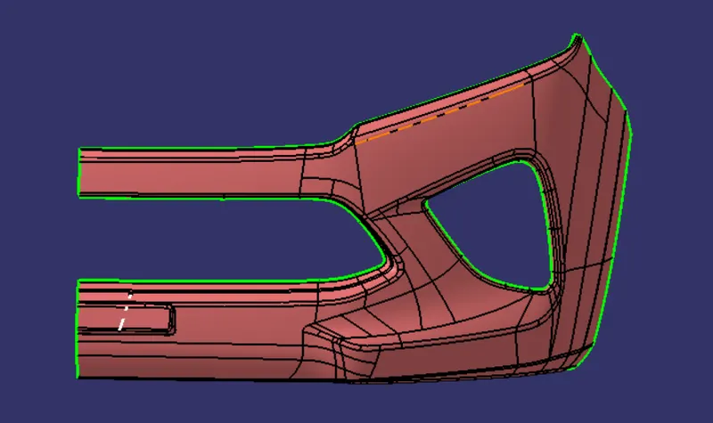
The A-surface or the styling surface is first checked for any gaps and other issues in its surfaces. This Surface acts as the input surface so any correction to be done should be with approval from the styling team or done by them. A- perfect surface is the one when a boundary is created, the lines are only on the edges of a component and its holes or cutouts as shown below.
DRAFT ANALYSIS OF A SURFACE:
Surface draught analysis is performed to determine whether the surface or item can be fabricated with the required draught angle.
Because the component would have shrunk towards the centre while cooling, a draught angle is required for it to clear the core and cavity surface.
In this design, the draught angle is 3 degrees. Because A is a single surface, there will be little colour difference.
CREATION OF B-SURFACE :
The A-surface is offset by 3.00mm since that is the necessary thickness.
Affected areas of the B-surface are closed using commands like Multi section, Sweep, Offset, and Extract.
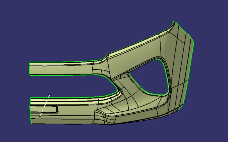
Finally, the offset surfaces formed previously are used to trim or unite all the created surfaces. The result was the creation of a single surface that will serve as the final B-surface.
By generating a complete border, a generated surface is examined for any holes or mistakes.
CREATION OF C-SURFACE :
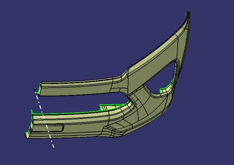
Another single surface, known as the C surface, connects the A and B surfaces.
With A surface serving as the reference surface and curve produced from the boundary of the same surface, it is made using sweep.
A-surfaces can also be produced by sweeping in a draught direction.
The image of the combined Class A and Class C surface is shown below.
CREATION OF CLOSED BODY :
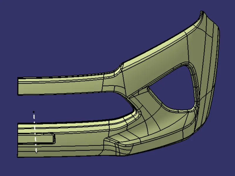
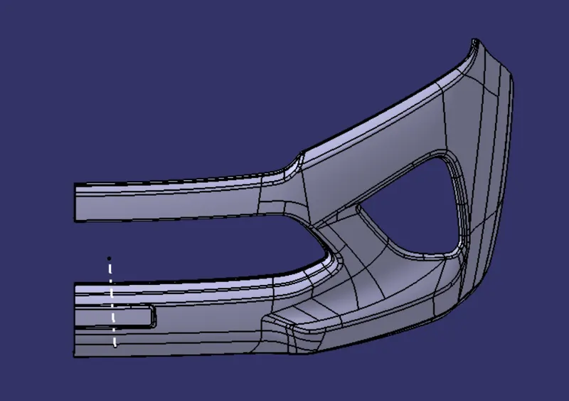
A closed body is created by joining together all three surfaces (A, B, and C).
The body is picked, and the boundary is chosen. It is clear that all surfaces are connected to one another to create a proper closed surface body since an error appeared.
Finally, using close volume, it is transformed to a solid body in the component design workbench.
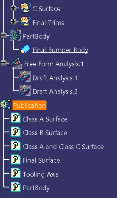
MODEL TREE:
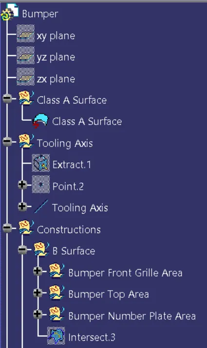
All of the geometrical sets are named for clarity, according to the constructed model tree.
Tooling axis, A, B, and C surface publications have been completed.
Additionally published are the closed surface body and Volume.
DRAFT ANALYSIS OF PART BODY:
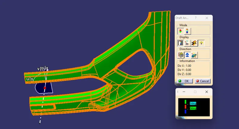
Draught analysis must be used to analyse the final solid part body. This is done to see if every part of the body meets the 3 degree draught angle requirement.
To help the part release from the mould, the vertical walls of the injection-molded component have a taper called a draught angle.
Draught angles are a necessary component of bespoke injection-molded products. Draught angles that face both the cavity and core sides are necessary for a functional injection-molded item. This will lessen the possibility of the parts being harmed and make sure they can be removed from the machine.
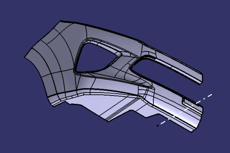
Images for the Bumper body are presented below after it has been examined utilising analysis.
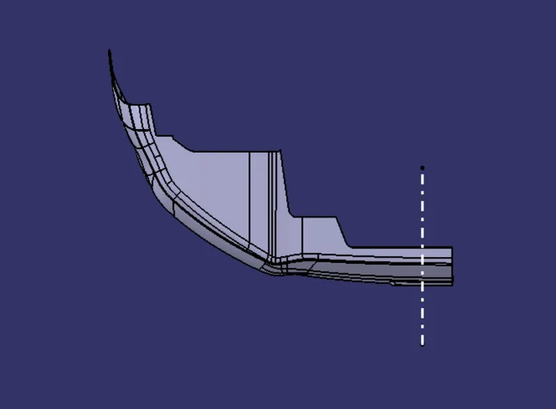
Views from the different orientations of the Bumper Part Body:
Isometric View:
Front View:
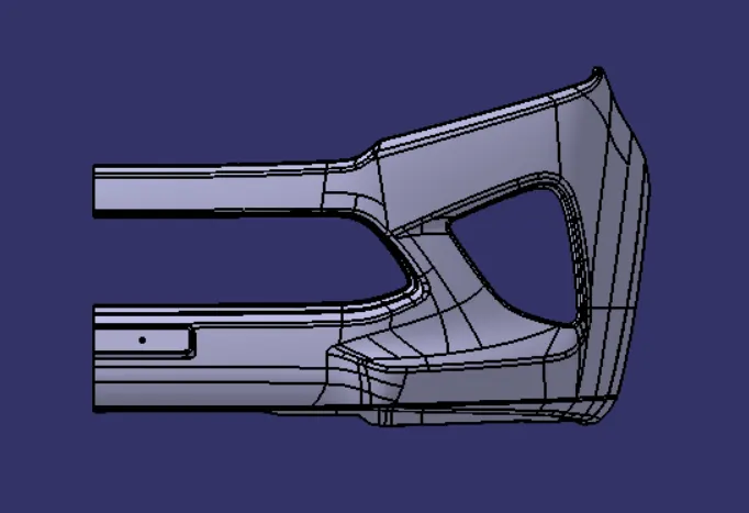
Back View
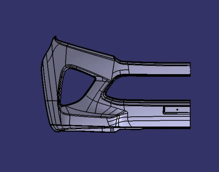
Left View:
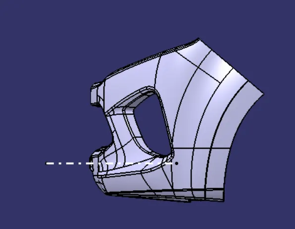
Right View:
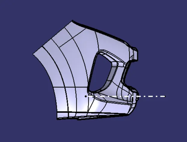
Top View:
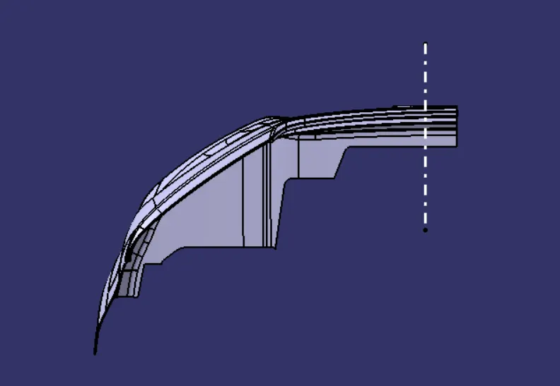
Bottom View:
Conclusion:
The component's feasibility for moulding without any problems was demonstrated by the draught analysis.
As a result, it meets all design and production requirements for an appropriate part.
The Design of Bumper Body Report is now complete.