Week 9 - Creating connection for Rear door
AIM:
The connections for the front door by using different 1D elements are taught in detail.
Now for the given Rear door FE model, Create and Apply different PIDs for different components. By using the same technique and the elements as shown in the video, Perform suitable connections. (No thickness need to be assigned to FE as intention is just to deploy connections)
(Refer “Model Requirements” in “Grading Policy” to know what to be done in the model)
Write a detailed report on why you choose a certain type of element for connecting certain parts of the door.
PROCEDURE:
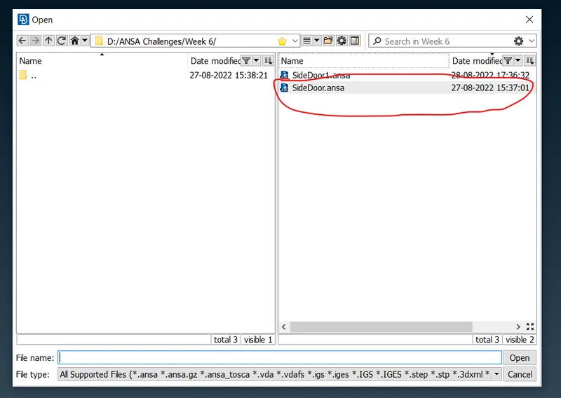
Import The Geometry.
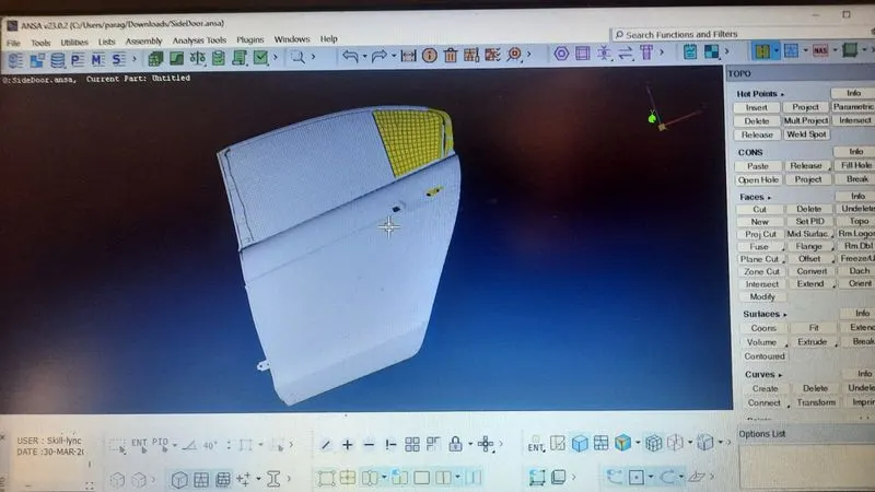
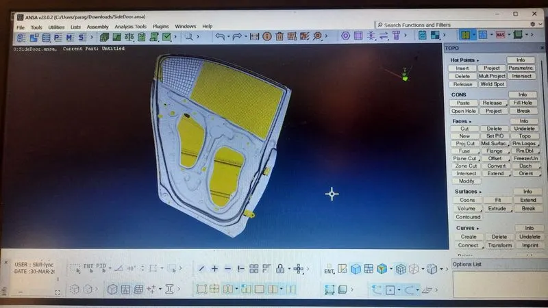
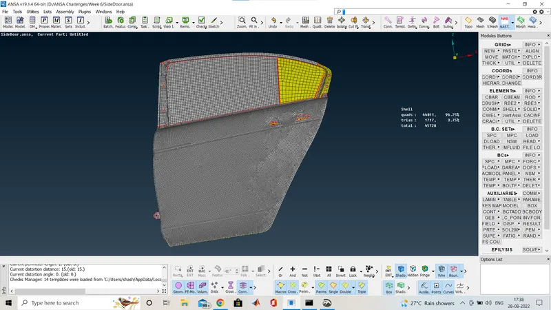
Check for the gemometry cleanup:
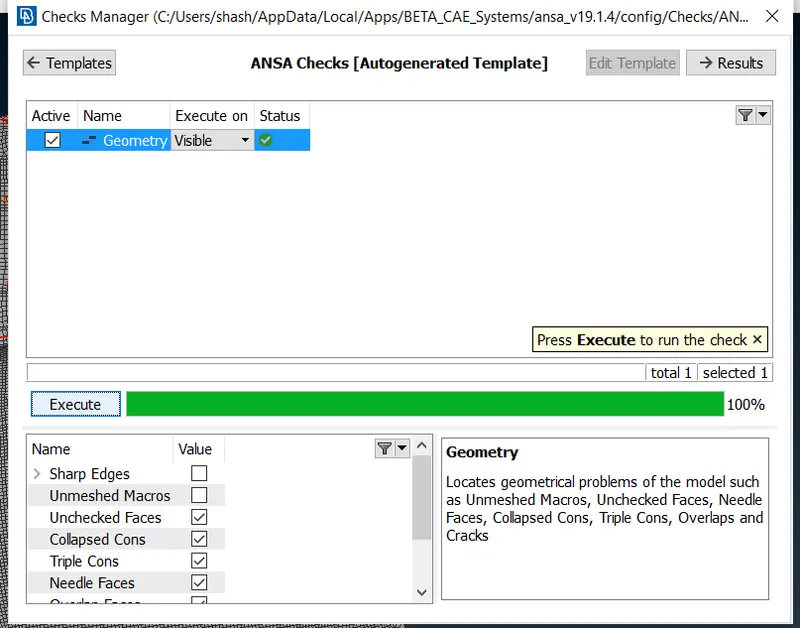
Here i go through the checks manager and check for the geometry cleanup,here as we have already provided the FE-model so no geometry cleanup required and also the meshing is done already as you can see below.
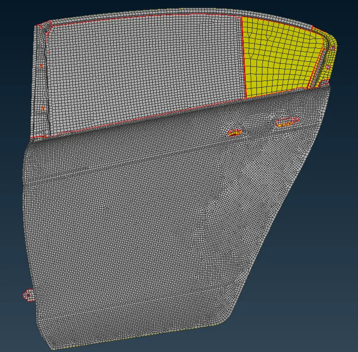
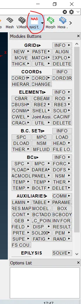
We directly go for the connection,so for connection i have to go to the NASTRAN Deck
Now i am going to show you bolt connection.
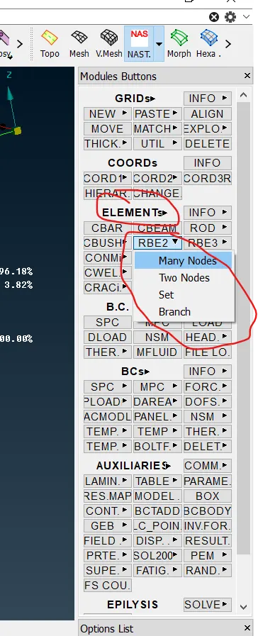
Here you can see the option Under NASTRAN Deck>Elements>RBE2>Many nodes
so fter selecting that many node option you are going to see the image as below
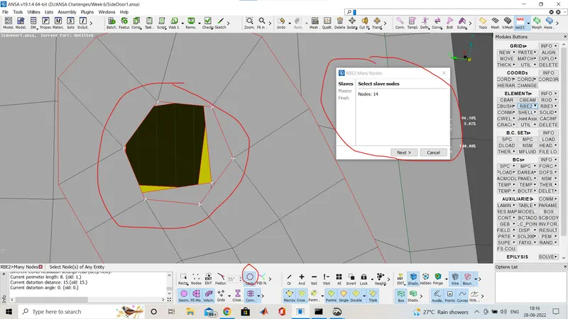
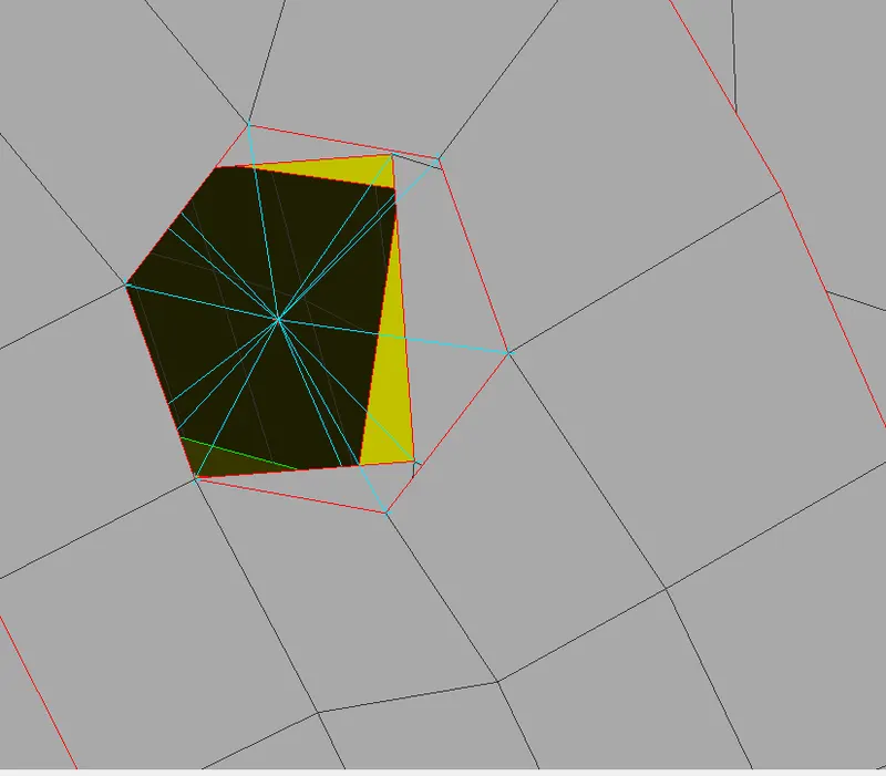
Here you have a winow one to select the slave nodes and by using loop selector i have selected all the node for bolt connectionas there is 4 holes and total 14 nodes so fter middle click the cluster bolt connection completed all the nodes joined through one master nodes.As sone below image.
Now i am goin to show another method of bolt connecton.
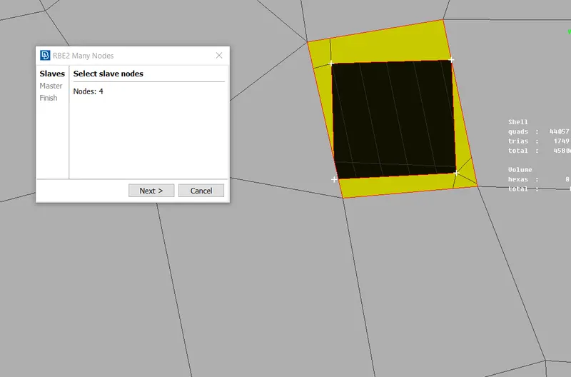
The same way i am going to select the many nodes option and now we are going to select only one bolt hole after making connection we will amke another bolt hole connection.as shown below,
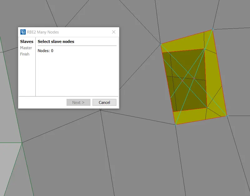
Here you can see we have two master nodes and two different connection now i am going to join this to node by Two node option under RBE2
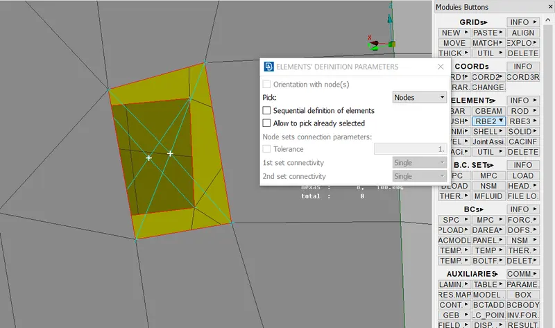
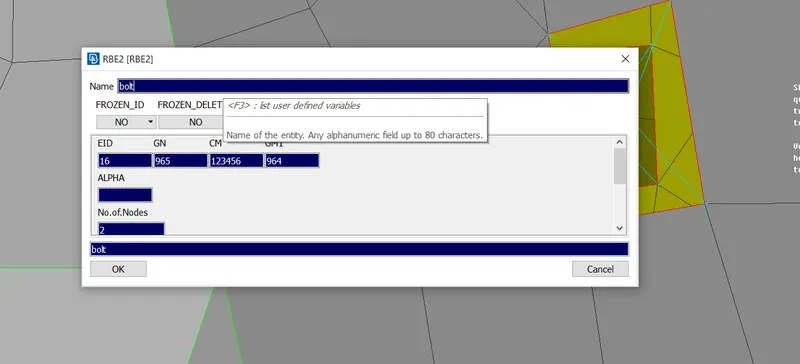
Here i selected the both master node and then do middle mouse click And we have to give the connection name,as shown below
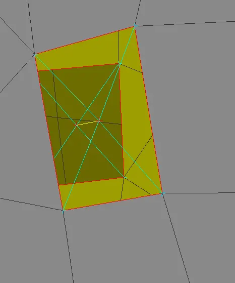
After that do middle click again and the both master node is conected ny a stem,as shown below.
Now i am goin to show weld connection we have used two type of weld connection spot weld and seam weld,i am going to show one by one so first spot weld.
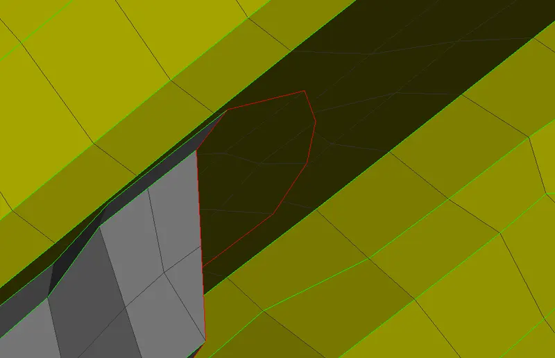
As you can see that we have two plates so no i am goin to join through spot weld.So first i creat a cog there
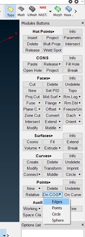
In the TOPO Deck>Points>ON COG>Edges
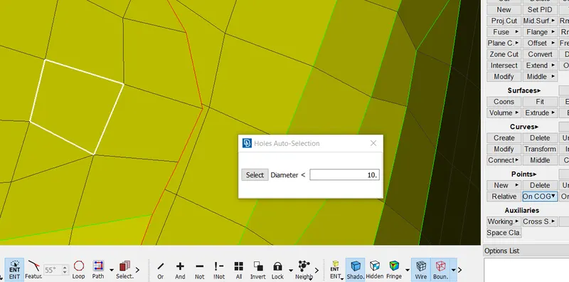
Select the elges where i want the cog point.
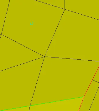
after middle click we got the cog point
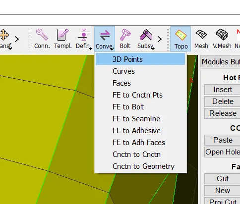
on the connection bar we have to select the convert option and then select 3D points
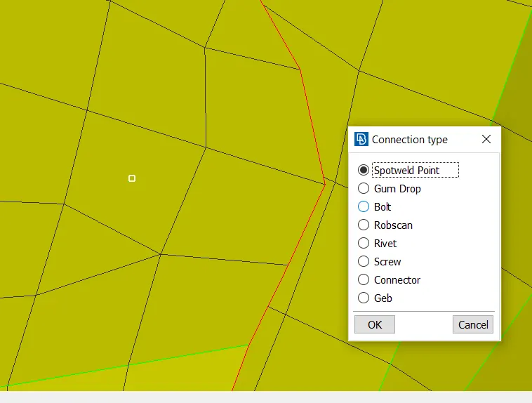
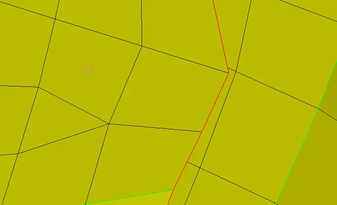
After selecting the poin the spotweld option we have created the spot weld poin as shown below image
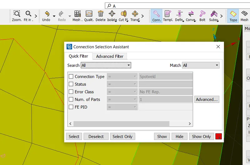
Then again in the connection bar we have to select the connect and then the window will pop up like shown above and then select that spotweld point and again the connection manager window will popup as shown below
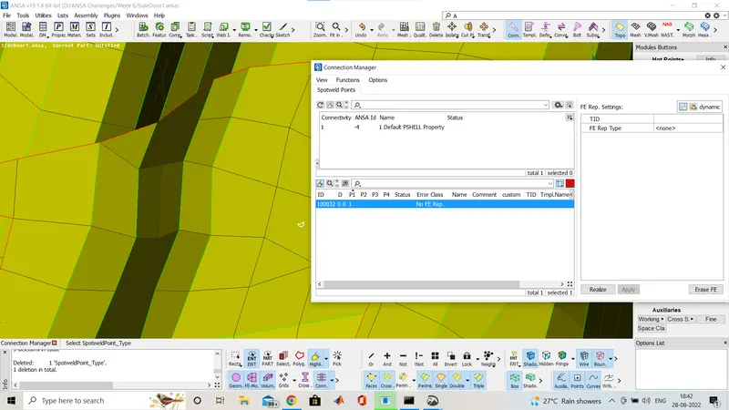
then we have to select the p1 and p2 which is part 1 and part 2 by clicking on the p1 and press f1 and selection window open where we have to give the weld spot as shown below one by one
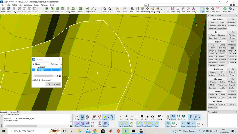
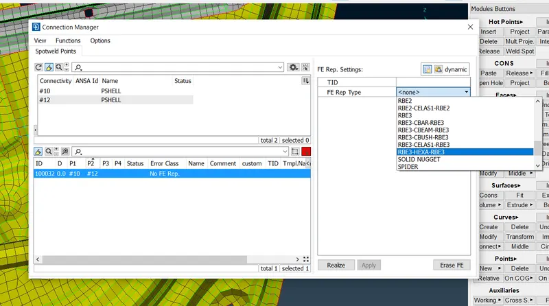
Ater that we have to select the type of connection it is here RBE3 HEXA RBE3 for spot weld
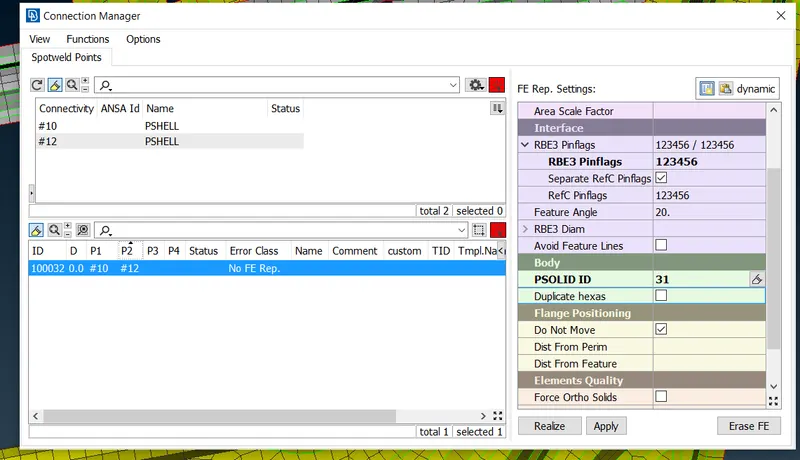
Now give the serch distance and make the RefC pinflag to also 123456 for all degree of freeddom, then creat solid id by clicking on that option and "shift+?" popup window as hown below
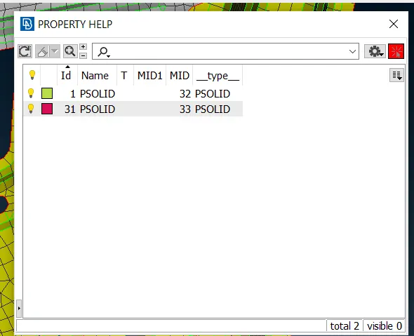
And select as hown above
then click apply and after that click realize and the spot weld connecton done as shown below image
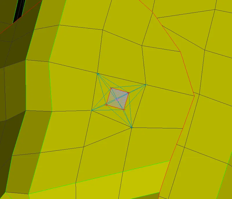
Now i am showing you the seam weld connection
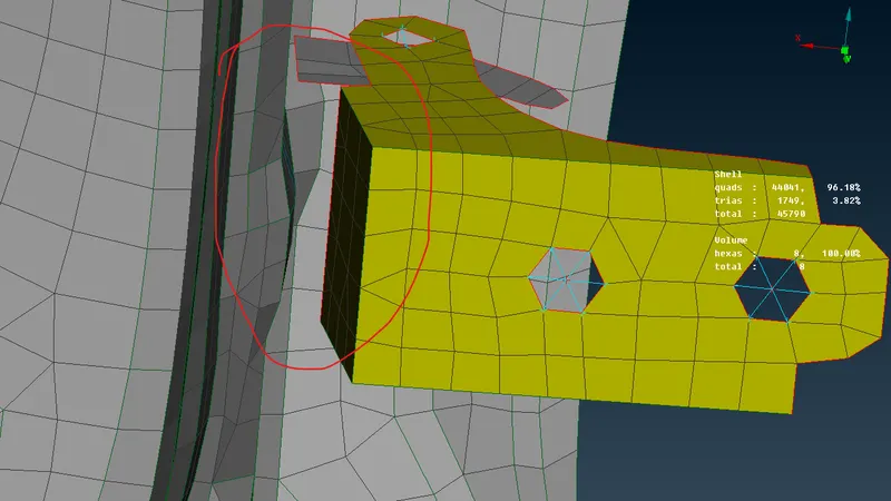
Here we can see the hinge part we have to weld it to the door.for that we dont have the weld data so we are asumin it so here we have a option in mesh deck>peremetre>Feat2curve
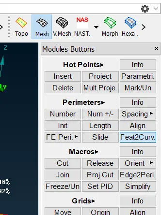
After this option selectgion we have to select the elge as shown below to creat curve.
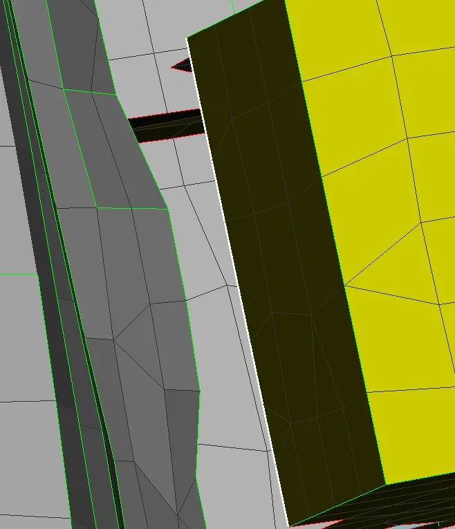
After that curve we arfe goin to off the fe so that we will see th curve below and then we will convert
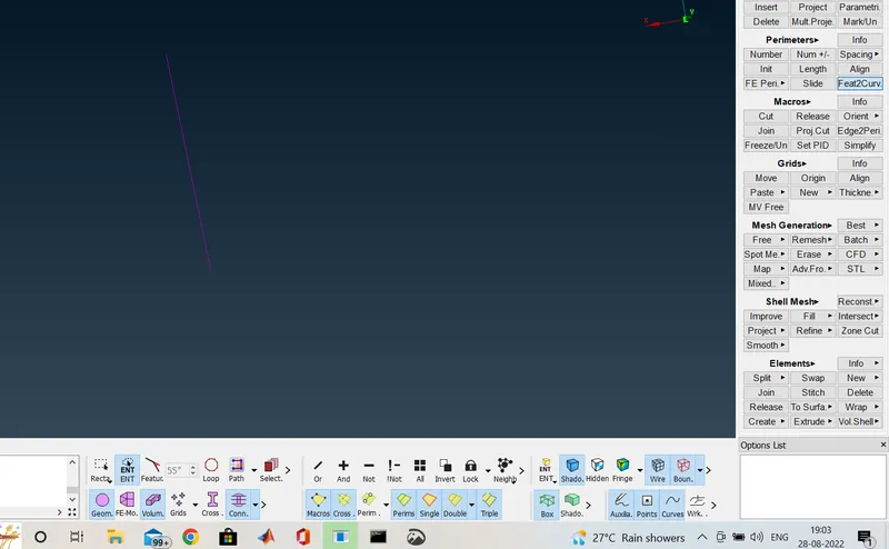
like earlier we have to select the convert option then curve and then select the curve and do middle click we will get the seam weld line
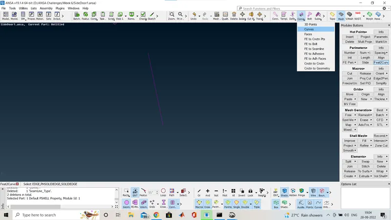
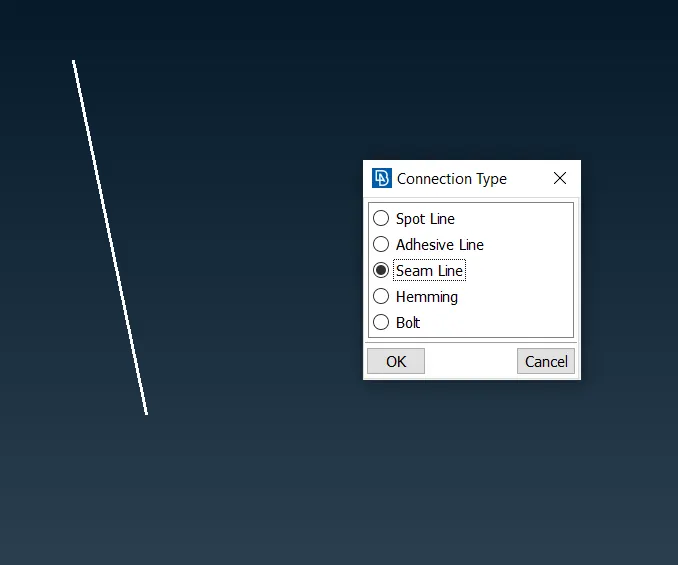
as you can see here
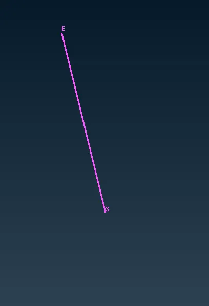
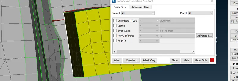
now select the connect option and on the fe and select the seam weld line and the connection manager popup
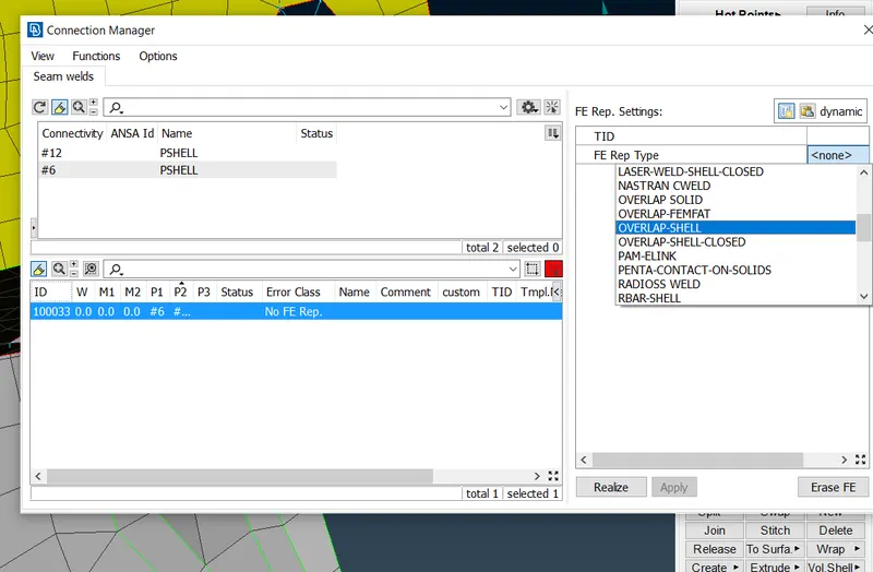
Select the part as told earlier and then we have to select the type of connection so here we have two type one is overlap[ shell and another is y joint shell so we select here overlap shell because both ARE in parallel
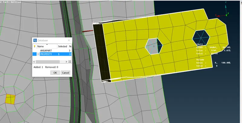
this is how select same part one by one
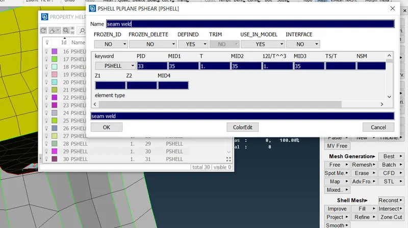
creat the weld id
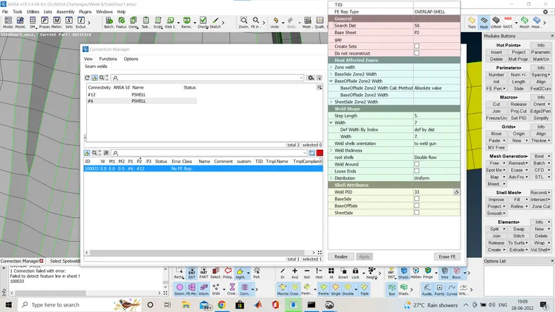
fill all the detailsa serch distance ,width of weld,step length,and then we click apply and then realize.
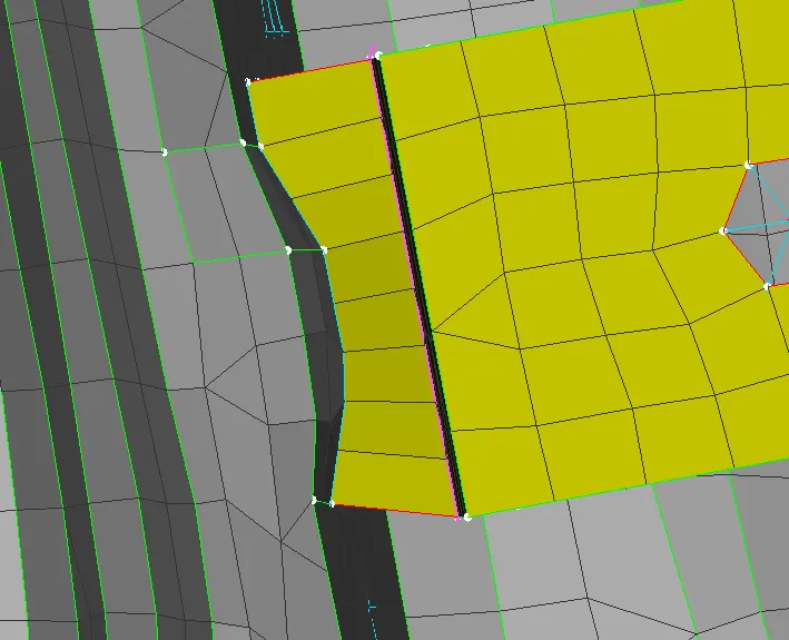
after that is seems like it as above.
Now i am going to show the door handle connection.
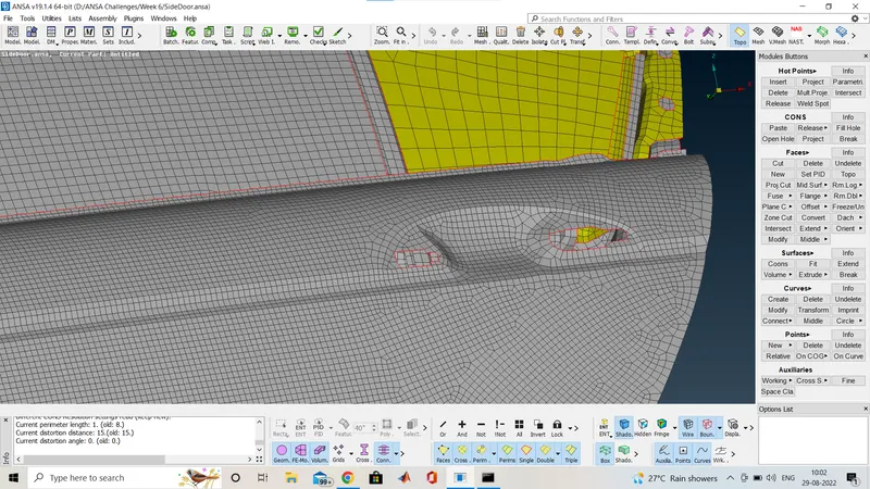
Here i am going to attach the door handle connection so first we select same RBE2 connection to both of the hole
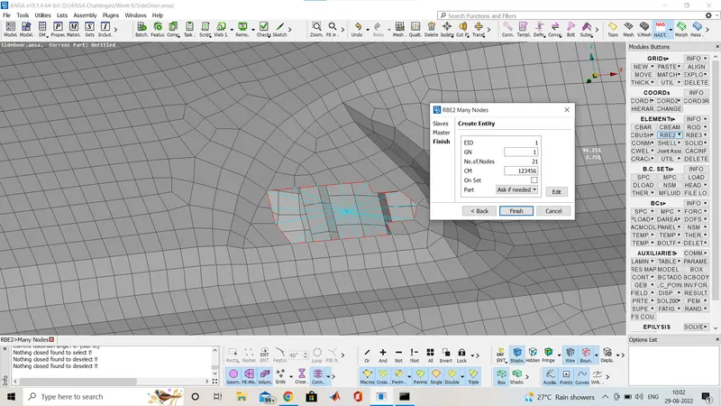
Here i made the RBE2 connection as told earlier
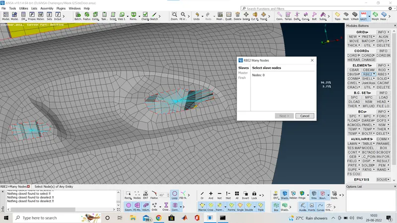
After making conection with RBE2 ,both the master node is connected with single node for that here we are using again RBE2 option.
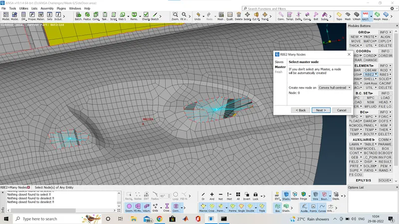
Here you can see above that i selected both the master node and i am getting a new master node and after middele click i am going to make the connection as shown below.
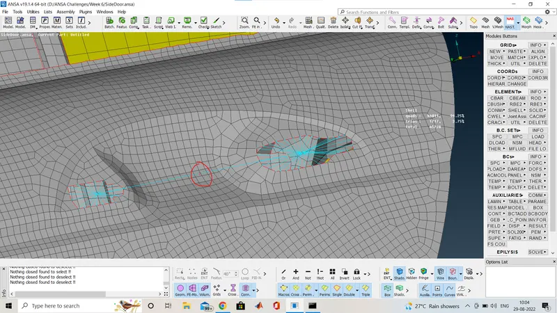
This is the connection made and the master node which is the cog of that handle there we are going to assign some mass.So for that i am using the CONM2 option.
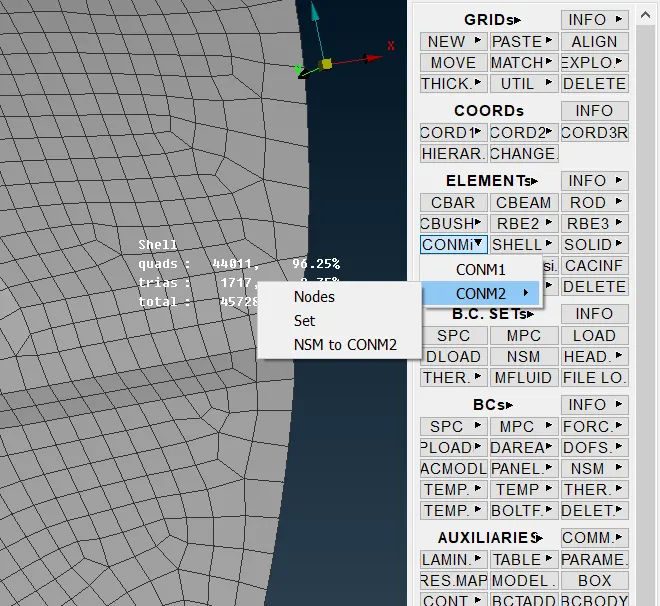
Here you can see we have selected the option from CONMi in Elements
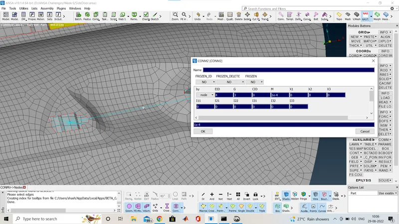
After selecting the master node a window will pop up and there we will assign the mass and the mas we have given it is in tonne.
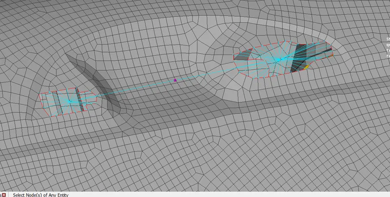
the final door handle connection looks like this
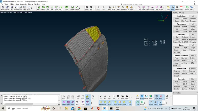
Now we have to make the window gass connection,so as there is some mechanism for opening and closing that window glass but while simulation we are going to give it as a rigid connection so no for making that connection first i am going to make the curve around the gass and for that we have to use the option in MESH Deck>Peremetres>Feat2curve
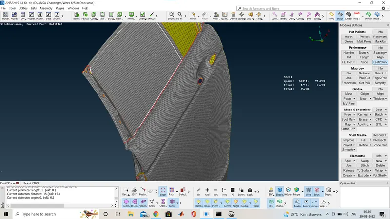
here we have use that option and select the edge of window glass after middle click we will have a curve around the edges of glss so for seeing that we have to off the FE model,and we are able so see as below image.And after that we have to copy that lower side curve in the y dirction side for that we are using the transform option>copy and move that curve by 10mm in y direction.
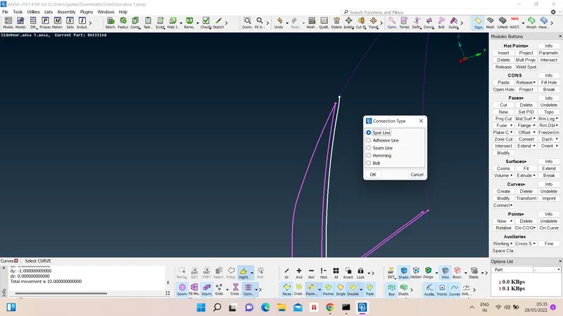
Now i have to convert that curve into spot line so same are using the convert option on the upper bar and select the curve one by one not in a single shot.
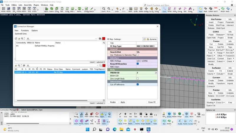
And after that we are using the connect option from the same bar and select the lower middle curve and a connection manager window will pop up.
And then again select the same p1 and p2 for making the connection and sapce i have given 10,and now select the connection as RBE3-CBUSH-RBE3, and frovide all the details like serch distance,keep all branches as ticked,and select the PBUSH ID,then click apply and then click realize. now the connection is made as shown below.
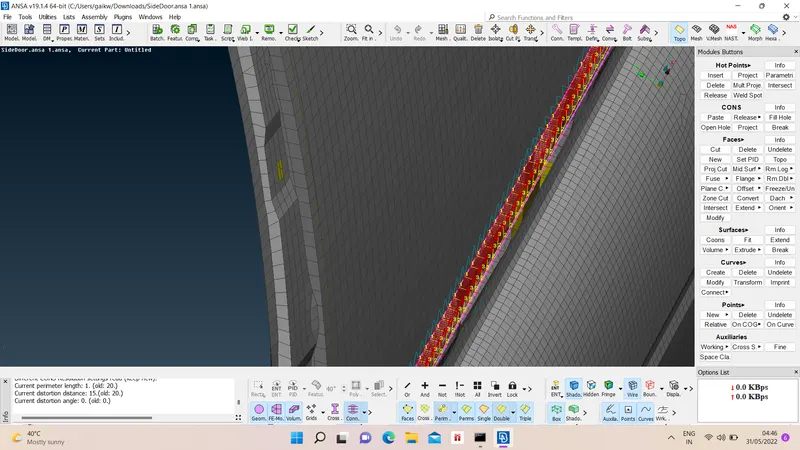
Here after the window all side connection we have to make the orientation of the CBUSH because if you see the bush every bush is in different directoin of axis so we are goin to make it on global axis and make it as coordinate as 0 so that it is on global axis
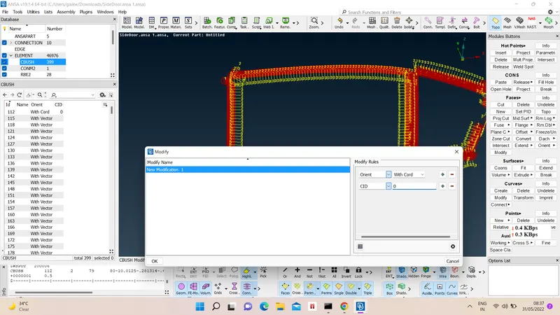
Open tha database and select the CBUSH and select all the CBUSH and click th option modify and make the orient to with cord.And add the CID as 0.
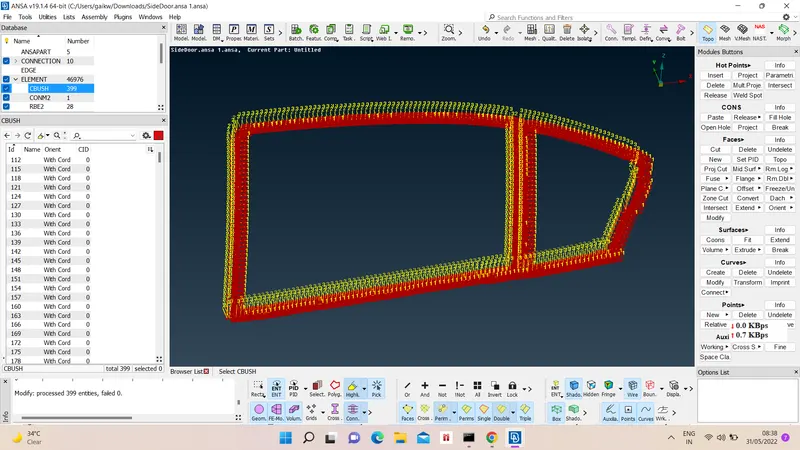
Now after clicking ok we shall see all the bush in one direction as shown above image.
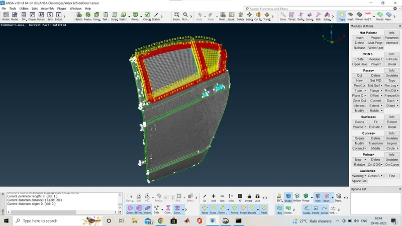
The final model is look like this after making all the connection.