Report On Tail Lamp Design
Report for Tail Lamp
Aim- To create a tail lamp from the given Class-A surface by following all the design parameters with attachment features, Positive mounting points and ECE(Economic Commission of Europe) regulations.
Introduction-
The lighting system of a motor vehicle consists of lighting and signalling devices mounted or integrated at the front, rear, sides, and in some cases the top of a motor vehicle. They illuminate the roadway ahead for the driver and increase the vehicle's visibility, allowing other drivers and pedestrians to see its presence, position, size, and direction of travel, and its driver's intentions. Emergency vehicles usually have distinctive lighting equipment to warn drivers and indicate priority of movement in traffic.
For the rear of a vehicle is provided by rear position lamps (also called tail lamps or tail lights). These are required to produce only red light and to be wired such that they are lit whenever the front position lamps are lit, including when the headlamps are on. Rear position lamps may be combined with the vehicle's stop lamps or separate from them. In combined-function installations, the lamps produce brighter red light for the stop lamp function and dimmer red light for the rear position lamp function. Regulations worldwide stipulate minimum intensity ratios between the bright (stop) and dim (rear position) modes, so that a vehicle displaying rear position lamps will not be mistakenly interpreted as showing stop lamps, and vice versa.
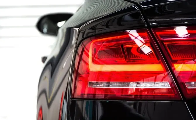
LENS
Lens is the outer part of a tail lamp unit which covers the reflectors and housing.
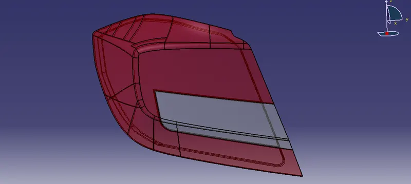
In Lens, there are two parts:
- Red Lens
- Clear Lens
Red Lens is used for Tail and Stop Light, Clear Lens is used for Turn Indicator and Reverse lights.
Material-: PMMA material is used for Tail Lamp, PMMA is a strong, tough, and lightweight material, which is less than half that of glass. It also has good impact strength, higher than both glass and polystyrene. It has a density of 1.17–1.20 g/cm3. PMMA transmits up to 92% of visible light (3 mm thickness), and gives a reflection of about 4% from each of its surfaces due to its refractive index (1.4905 at 589.3 nm) and PMMA ignites at 460 °C (860 °F).
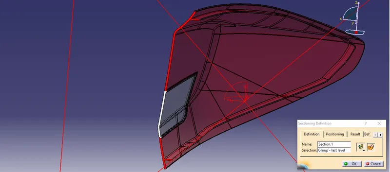
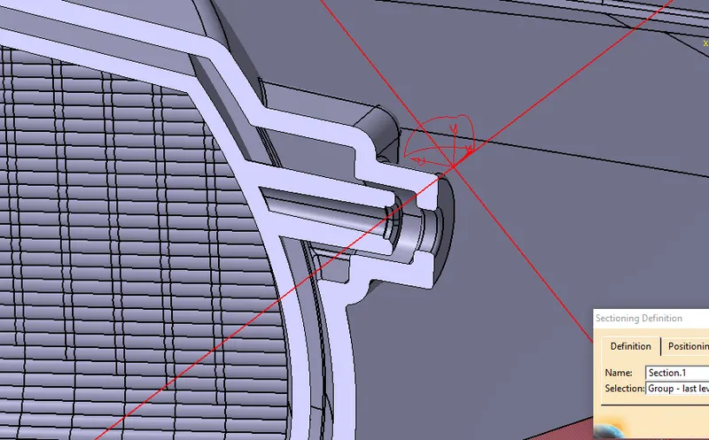
Manufacturing Process of Lens- Lens is manufactured by injection molding process but exact process is called as "Insert molding or 2K Molding/2 shot molding "('2K' stands for german word 'Zwei Komponenten' in english 'Two component'). In Insert molding/2K Molding- Initialy, an insert part is injection molded, which is clear lens in the tail lamp case and that molded part(Clear Lens) is used as an insert in other cavity, onto which the other part is formed by injection molding process.
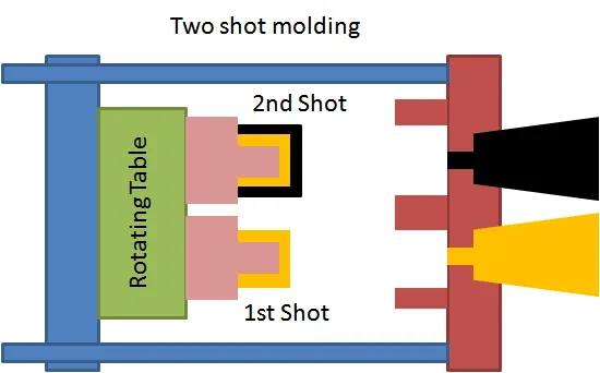
Insert Molding Section
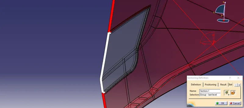
REFLECTOR
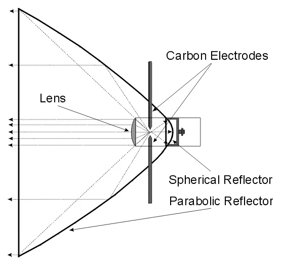
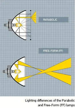
Reflectors are the internal part of a tail lamp unit, reflectors are the part which reflects the light of the bulb fitted into the tai lamp unit. Reflectors are shiny in appearence which helps them make more refractive to enhance the light. Reflectors shape are made of a parabola. Parabolic reflectors gather the light from the focus of the reflector and return it in a concentrated beam in the direction the reflector is facing. This concentrated beam of light can be directed to the horizon and can be manipulated to provide a very useful light.
Significance of parabola- A parabola, parabolic or paraboloid reflector is a reflective surface used to collect or project energy such as light, sound or sound waves. The surface generated by a parabola revolving around its axis.
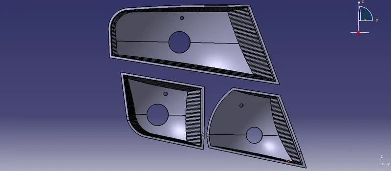
There are three different reflectors
- Tail and Stop Light reflector
- Turn indicator Light reflector
- Reverse Light reflector
Material- Tail lamp Reflectors are made of Polycarbonate. Polycarbonates are strong, tough materials, including temperature resistance, impact resistance and optical properties. Polycarbonate has a glass transition temperature of about 147 °C (297 °F).
- To create reflectors
The major shape of reflectors are depend upon the Class-A Surface.
- The shape of reflectors is made with Parabola.
- To create the reflectors, the sketch is drawn and swept with 3 degrees draft for easy tooling.
- There are Rollets or Flutes on the reflectors surface to uniformly reflect the light.
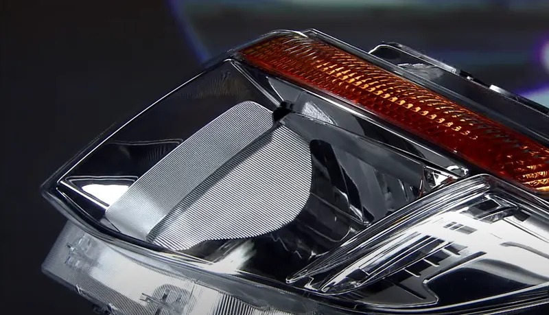
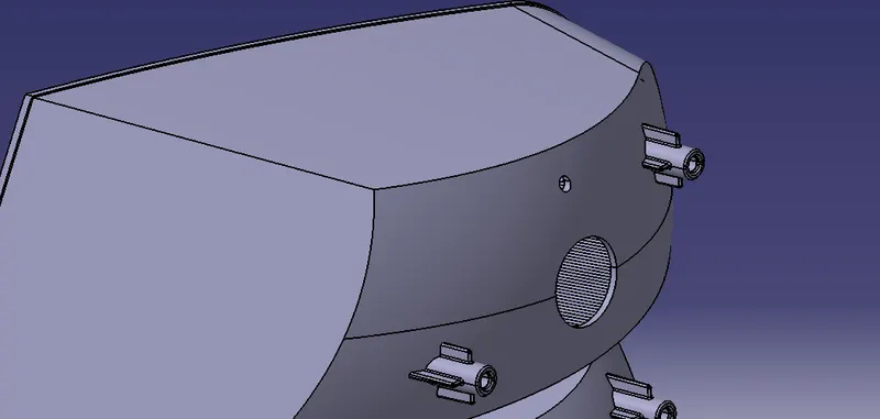
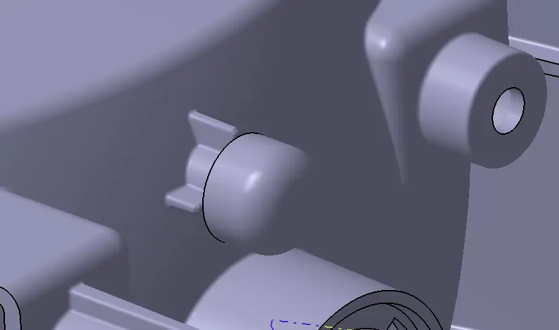
- Reflectors have vent cap holes which helps to reduce condensation in the lamp unit.Plastic cap vents to block water and dust ingress inside the lamp are called vent caps. Headlamps and tail lamps have to cope with environmental conditions that change every day. What’s more, they have to be protected against dust, dirt, deposits, and condensation if they are to work effectively and guarantee drivers a clear view at all times. Various options are available to automobile manufacturers and suppliers for removing moisture from headlamps. When selecting a venting membrane as an option, the solution must be able to equalize pressure within the headlamp housing, form an effective barrier against dirt and water ingress, and be able to reduce condensation.
- Condesation- In regard to car's Head/Tail lights, the phenomenon takes place when the outside air is cooler than the air inside the lighting assembly. The warmth of the bulbs paired with the cold weather can create the perfect environment for condensation, leading to the formation of water droplets inside the headlights.
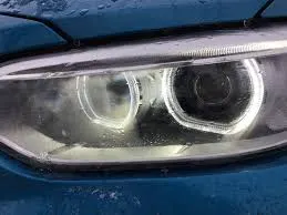
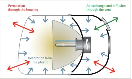
- To reduce Condensation Vent Caps are provoded.
- Bulbs used in the lamp are:
Stop Function- PR21/5W
Turn Function- PY21W
Reverse Function- W16W
- Mounting of Reflectors
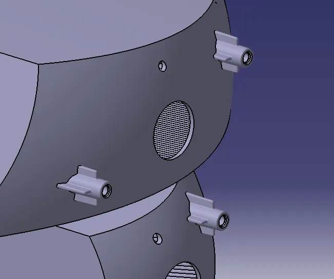
M4x10 Screw Boss
- According to ECE R48,R23,R7,R6 ,The maximum height at which the tail lamp should be position is 1500mm from the ground plane, the ground plane is taken at 500mm away from the axle centre
- And from the centre it should be minimum 600mm.
- ECE Regulations
- For Tail function- Vertically it should be visible 15 Degrees upward and downward.
- For Turn function- Vertically it should be visible 15 Degrees upward and downward.
- For Reverse function- Vertically it should be visible 15 Degrees upward and downward.
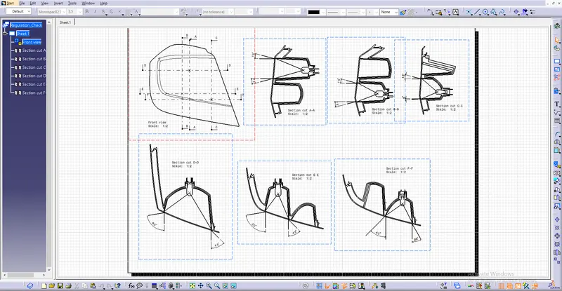
- For Reverse function- Horizontaly- It should be visible 80 Degrees Outward and 45 Degrees Inward.
- For Turn function- Horizontaly- It should be visible 80 Degrees Outward and 45 Degrees Inward.
- For Tail function- Horizontaly- It should be visible 80 Degrees Outward and 45 Degrees Inward.
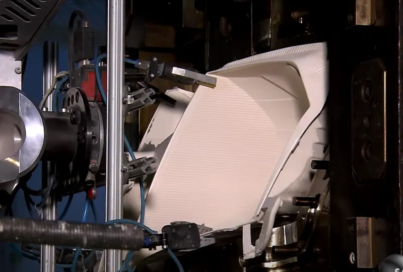
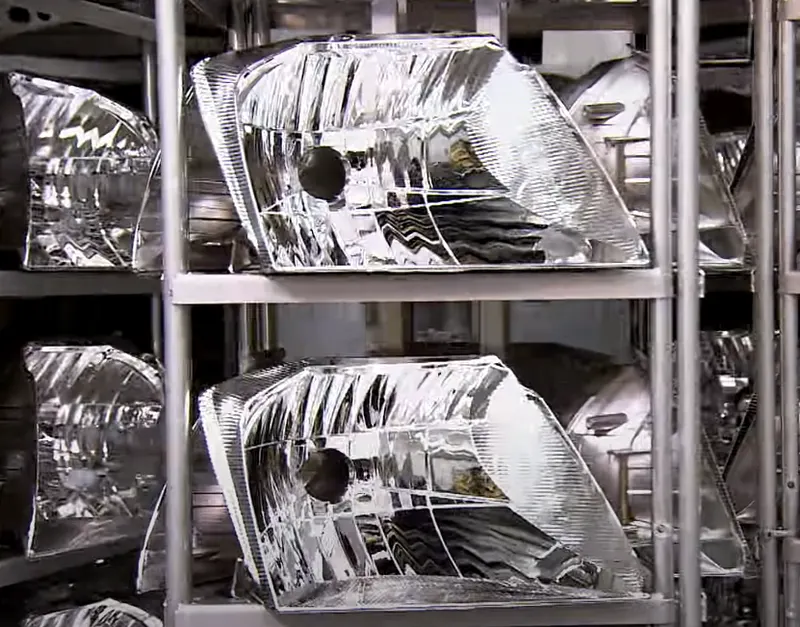
Manufacturing Process of reflector- Reflectors are made by Injection molding process, tail light reflectors are made of Polycarbonate(PC). To make reflectors reflective, The Aluminum coating is done over the reflectors, in which the aluminum is heated and air blown over the reflectors in a close heated chamber, this process is called as Metallization Process. By this process aluminuim coating is done over reflector evenly.
HOUSING
Housing is a part which covers the reflectors and joins with the lens. Housing contains the bulb holders and seating area in which the bulb fits, It contains the reflector mounting points to mount the reflector on the housing and It has many mounting features through which the light unit can be mounted on the vehicle.
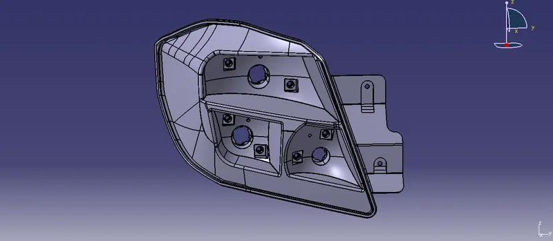
Material- Housing made of ABS(Acrylonitrile butadiene styrene). Housing is a unit which holds all the parts of a light unit and mounts on the vehicle. So the housing should be strong and sturdy and ABS is the perfect material to make housing of a tail lamp unit.
ABS provides favorable mechanical properties such as impact resistance, toughness, and rigidity when compared with other common polymers. A variety of modifications can be made to improve impact resistance, toughness, and heat resistance. Its glass transition temperature is approximately 220 °F (104 °C).
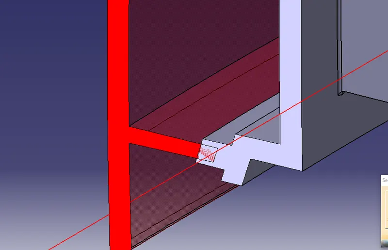
- Housing has a welding track which joins with the Lens welding track.
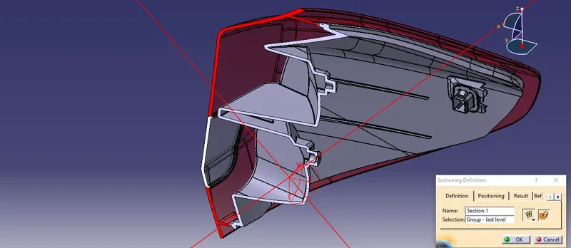
- Housing has bulb holder in it to hold the bulbs for the reflectors.
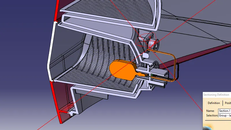
- Housing has Reflector Mounting points
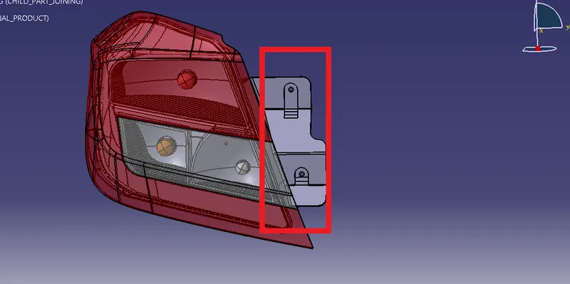
- To attach the tail lamp to the car body a positive mounting should be designed. It will be input as BIW or we can create a reference surface and use it as biw panel, Design a mounting flange and create an area to mount the M5 screws and make a slope so that the water can slide through that slope
- It has 2 stud mounting and 1 clip mounting to mount on the BIW panel.
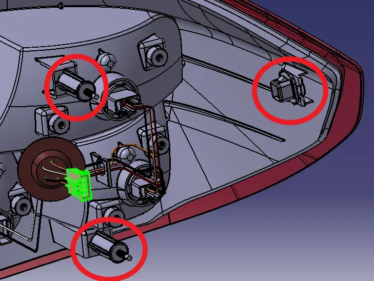
- It has Positive mounting of M5 bolts to mount the lamp unit on the vehicle. Positive Mounting Point is where it does not accumulate water in the different weather conditions.
WIRING HARNESS
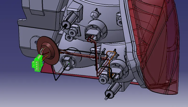
Wiring harness is electrical connection between electrical euipments to the electric source like like terminals and Wiring harness is the wiring structure that protects the lights from outside environment and water
- Grommet was created so that the wiring can be separated from inside the housing and from outside.
- The water slides and stops at the grommet and prevents the water entering the housing.
- A routing feature is created to keep the wires held in place and helps the wires get not tangled
- Given connector have 6 poles and we have 7 poles for the lights , we have common wire for earth which is black
- Here, Tail and stop function have same pole.
HOT PLATE WELDING
Hot plate welding, also called heated tool welding, is a thermal welding technique for joining thermoplastics. A heated tool is placed against or near the two surfaces to be joined in order to melt them. Then, the heat source is removed, and the surfaces are brought together under pressure. Hot plate welding has relatively long cycle times, ranging from 10 seconds to minutes, compared to vibration or ultrasonic welding. However, its simplicity and ability to produce strong joints in almost all thermoplastics make it widely used in mass production and for large structures, like large-diameter plastic pipes.
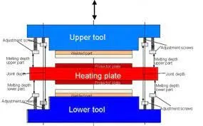
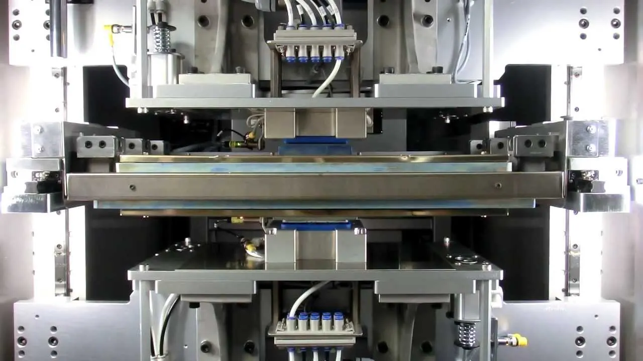
HOT PLATE WELDING SECTION
The Assembly and the Child Part drawing for the taillamp
Assembly Drawing
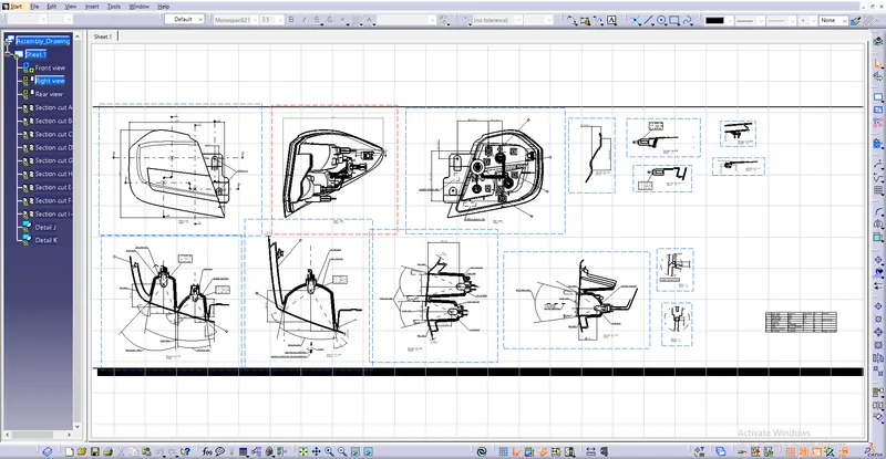
Child Part drawing
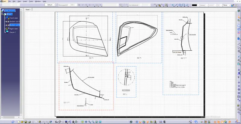
Lens drawing
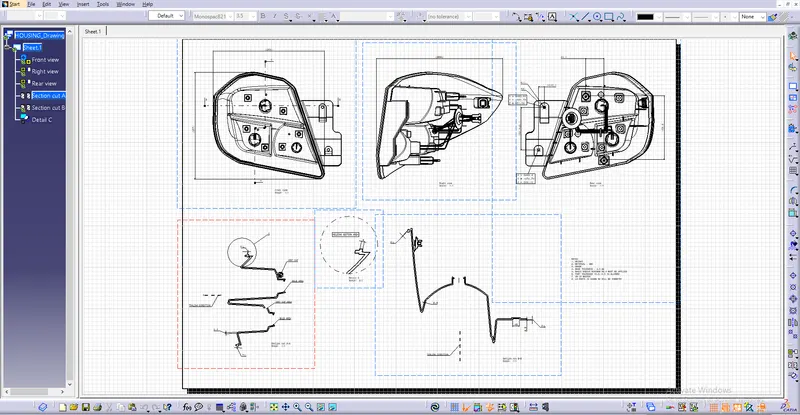
Housing Drawing
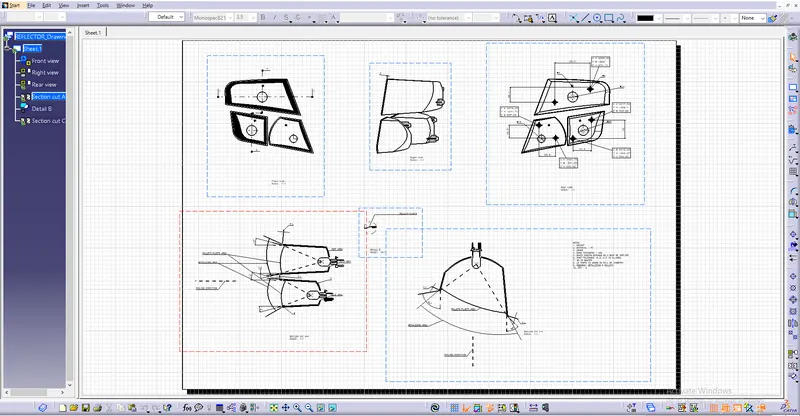
Reflector Drawing
Different Views of Tail Lamp
Front View
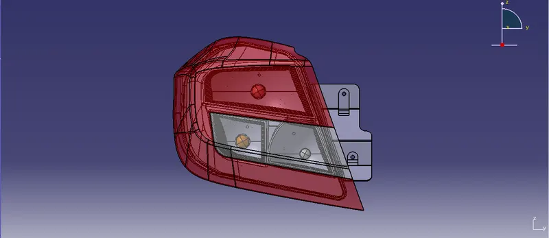
Left Side View
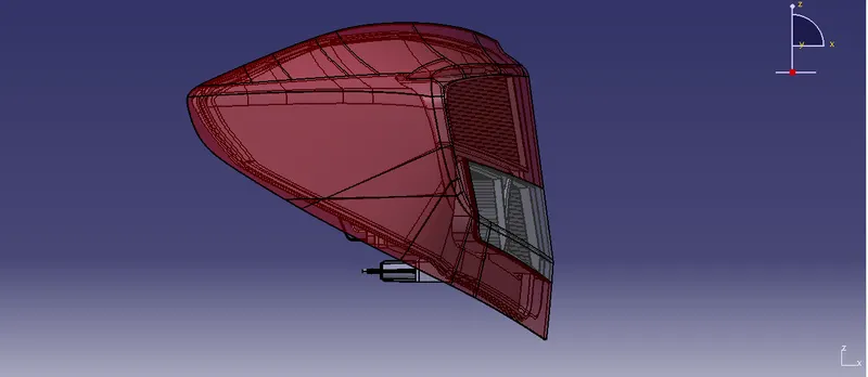
Right Side View
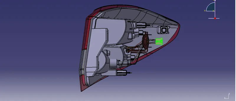
Rear View
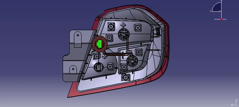
Isometric View
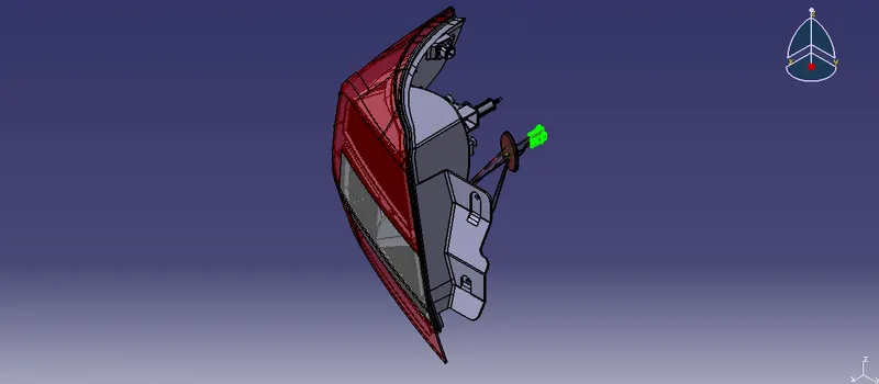
Rendered Images
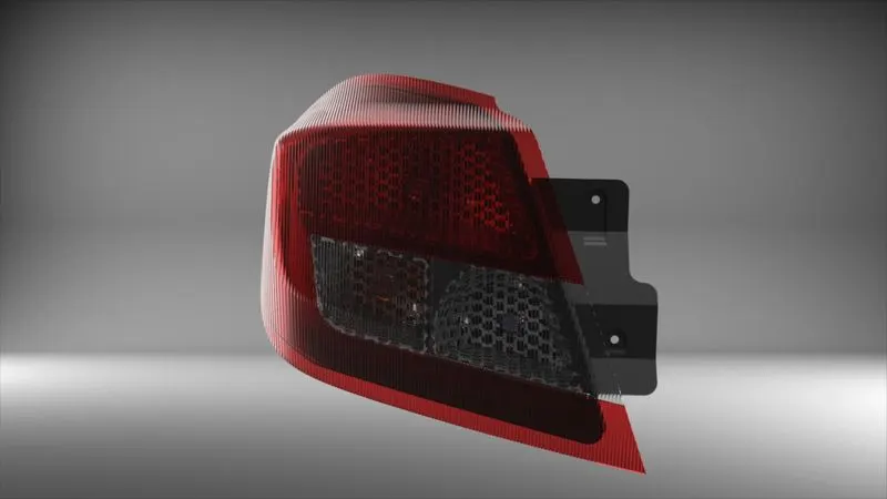
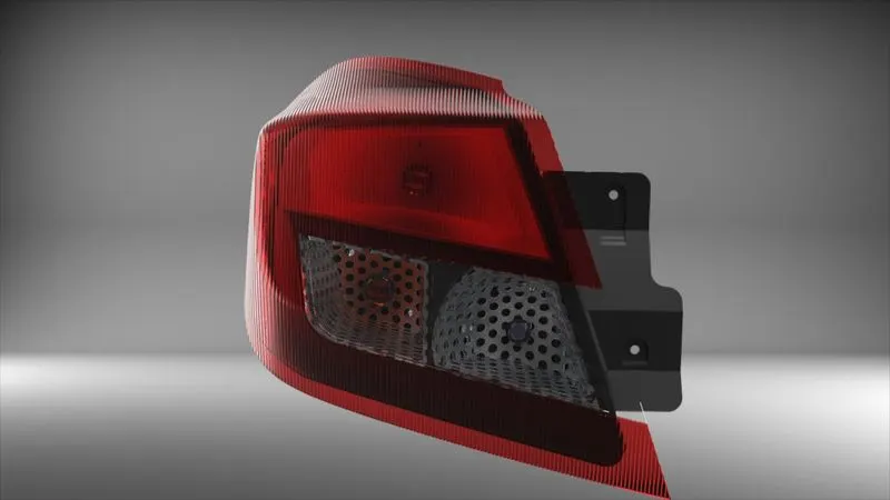
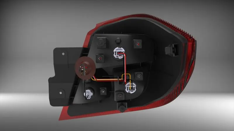
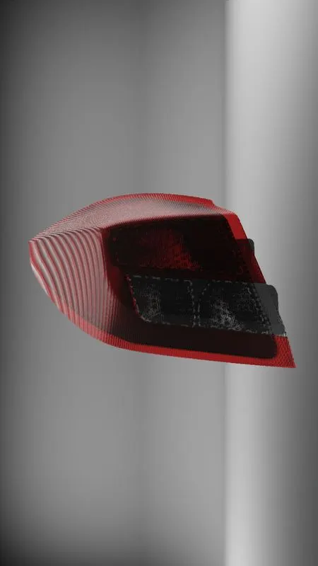
Conclusion- Thus, the tail lamp was designed with the given surface by following required design guidelines, parameters and ECE regulations and Assembly and Child parts drawings are also created.