Wiring harness routing & packaging Rules Week 3 Challenge
P CLAMP
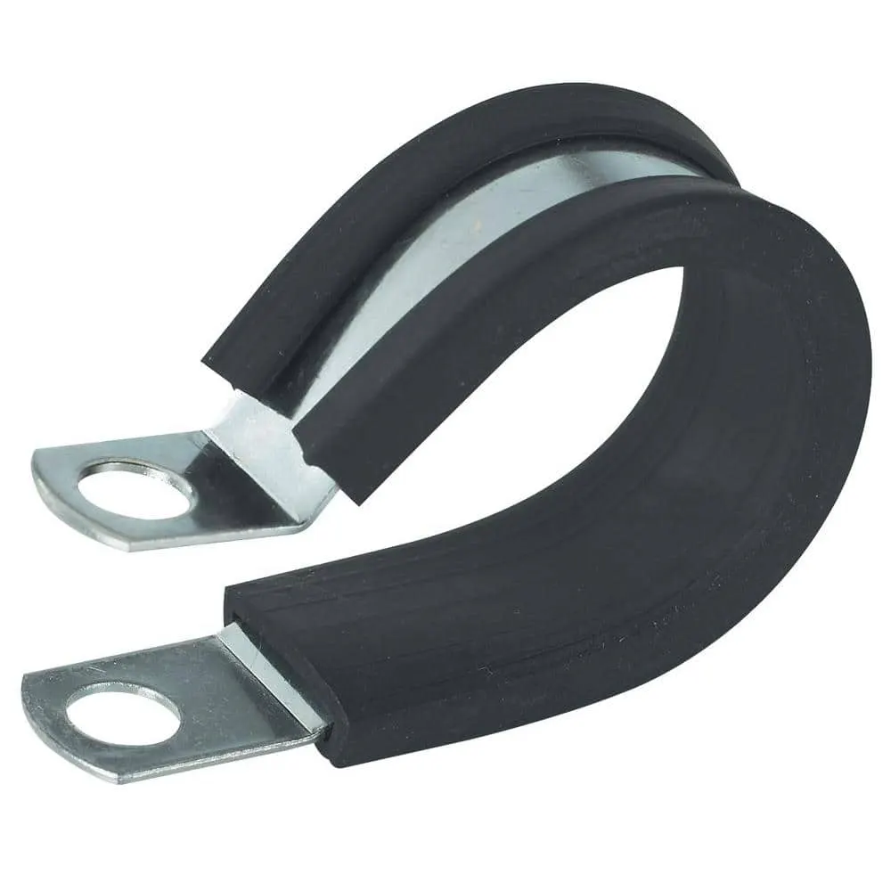
P clamps are used to mount or hold the different housing in wiring harness and the other applications.
To Define P Clamp:
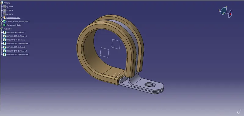
- First Defined the Geometry parameters like Points and Planes.
- Define Support part command is used to convert it into electrical support.
- Took the entry point and plane, base plane and exit point and plane of the P clamp.
- Defined Entry, Exit and Base plane using support definition command.
Back shell
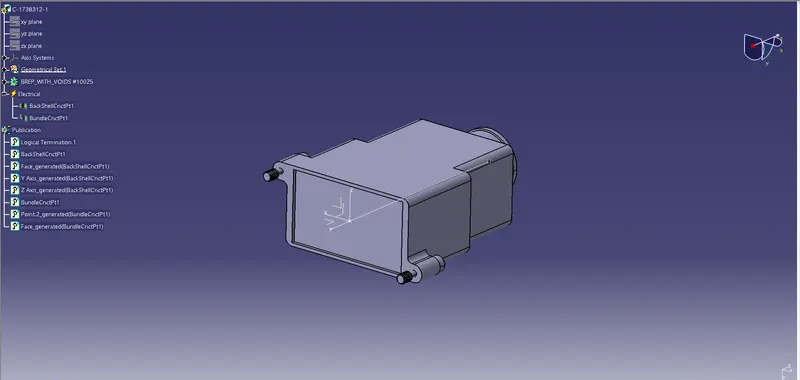
Back shells are the dressing and packaging devices/covers used at the end of the connectors as a retention devices.
To Define Back Shell:
- First Defined the Geometry parameters like Points and Axis System.
- Defined the geometry as Back Shell using command Define back Shell > Electrical Device Definition.
- Defined as Back shell Connection point and Connection Bundle point.
COT TUBES
|
Name |
ID (mm) |
OD (mm) |
Thickness (mm) |
|
15mm COT |
12 |
15 |
1.5 |
|
20mm COT |
17 |
20 |
1.5 |
|
35mm COT |
32 |
35 |
1.5 |
|
10mm COT |
7 |
10 |
1.5 |
|
5mm COT |
3 |
5 |
1 |
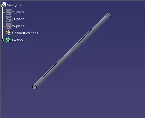
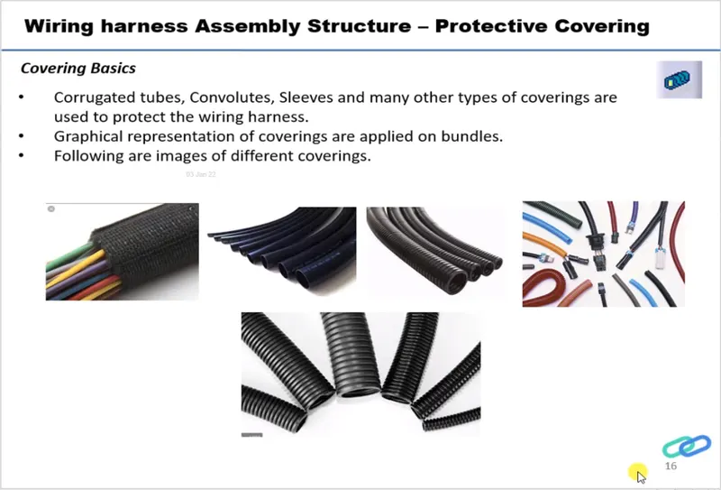
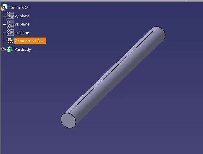
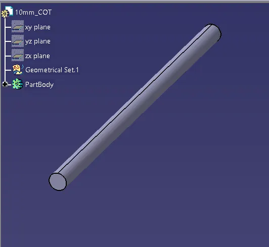
Corrogated or COT Tubes are made according to requirements in differnet sizes.
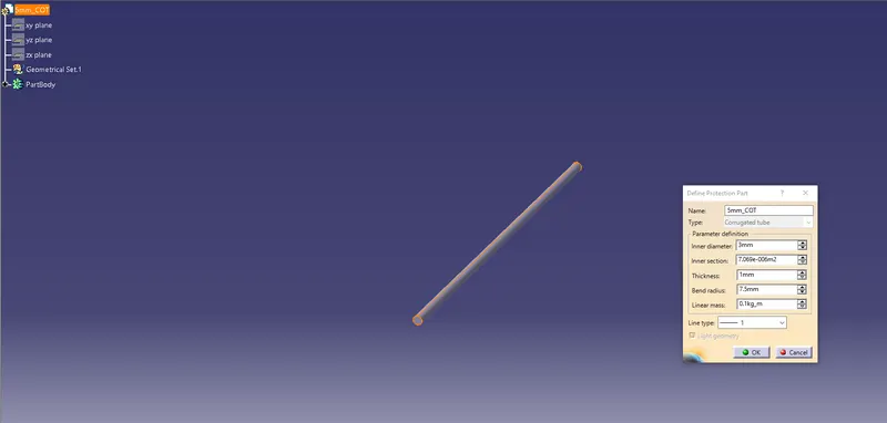
To make COT Tubes
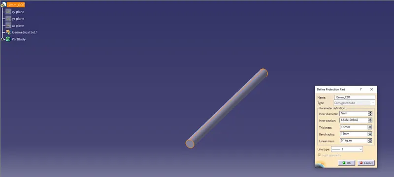
- Create a part body.
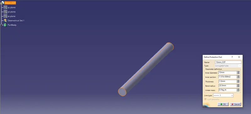
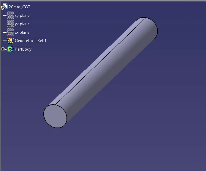
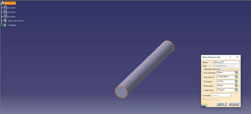
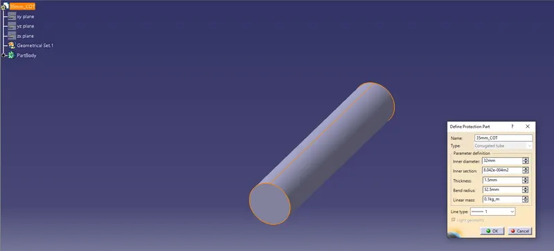
- Use Protection Covering Command
- Select Type and parameters to make COT TUbes, given 1.5 times bend radius.
- Created a Catalogue named "Slit Tubes" and added all the Cot tubes to use them multiple times.
|
15mm COT |
12 |
15 |
1.5 |
|
20mm COT |
17 |
20 |
1.5 |
|
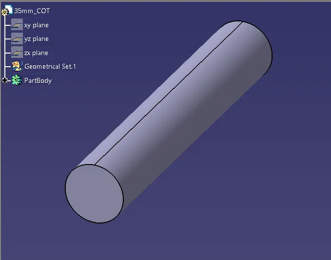
35mm COT |
32 |
35 |
1.5 |
|
10mm COT |
7 |
10 |
1.5 |
|
5mm COT |
3 |
5 |
1 |