Project
Aim:
To prepare a technical report of Simulation of BAJA All-Terrain Vehicle(ATV) under different conditions.
Objectives:
Carry out a system-level simulation of an All-terrain Vehicle and prepare a technical report explaining the model properties & comments on the results.
ALL TERRAIN VEHICLE:
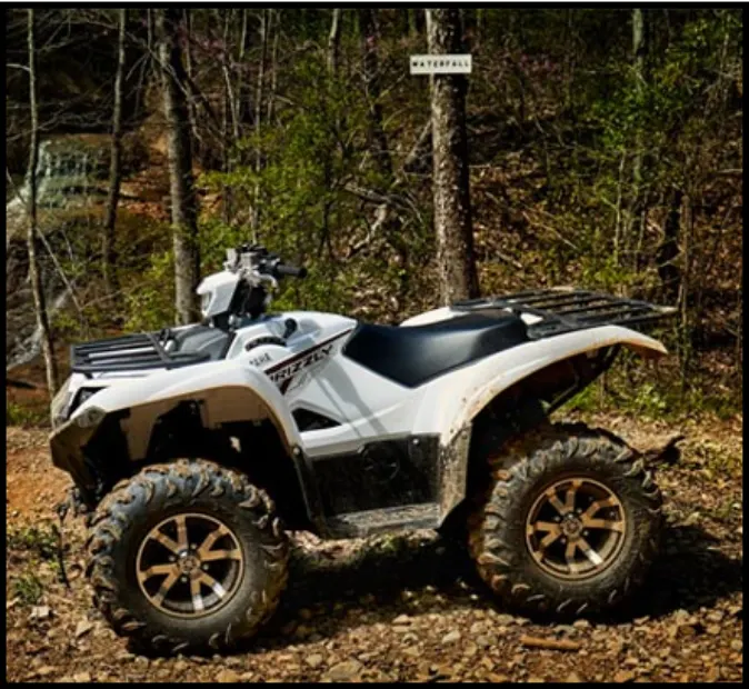
An all-terrain vehicle (ATV) is defined as a motorized off-highway vehicle designed to travel on four low-pressure or non-pneumatic tires, having a seat designed to be straddled by the operator and handlebars for steering control. ATVs are subdivided into two types as designated by the manufacturer.
- Type I ATVs are intended by the manufacturer for use by a single operator and no passenger.
- Type II ATVs are intended by the manufacturer for use by an operator and a passenger, and are equipped with a designated seating position behind the operator.
Similarly, riders must also consider the various ATV sizes.ATVs are not “one size fits all.” The ATV industry recommends all riders operate an ATV intended for their age. Youth model ATVs are designed for smaller hands and feet, and travel at slower speeds appropriate for their age.
Study 1:
case 1
SIMULINK MODEL FOR BAJA ATV WITH CVT:
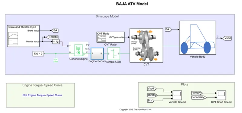
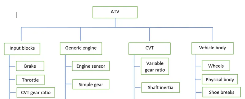
From this model, the components presented was
Brake and throttle input signal:
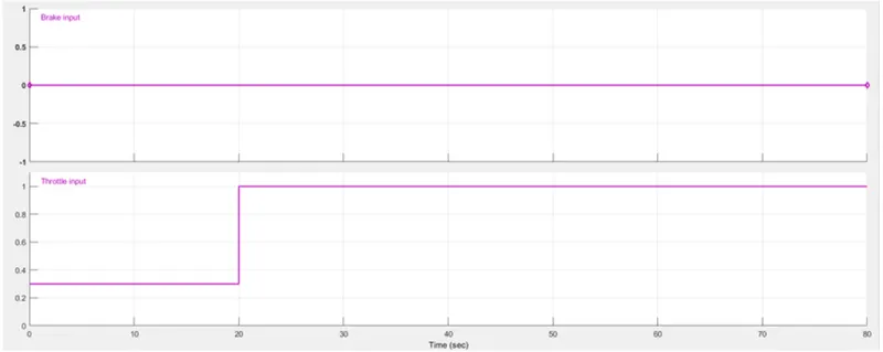
- No brake is provided
- A Constant throttle of 0.3 for the first 20 seconds, and full throttle of 1 for the remaining
- These two parameters are fed into the engine
Generic Engine:
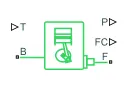
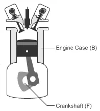
The Generic Engine block represents a general internal combustion engine. This block is a suitable generic engine for spark-ignition and diesel. Speed-power and speed-torque parameterizations are provided. A throttle physical signal input specifies the normalized engine torque. Optional dynamic parameters include crankshaft inertia and response time lag. A physical signal port outputs the engine fuel consumption rate based on the fuel consumption model that you choose. Optional speed and redline controllers prevent engine stall and enable cruise control.
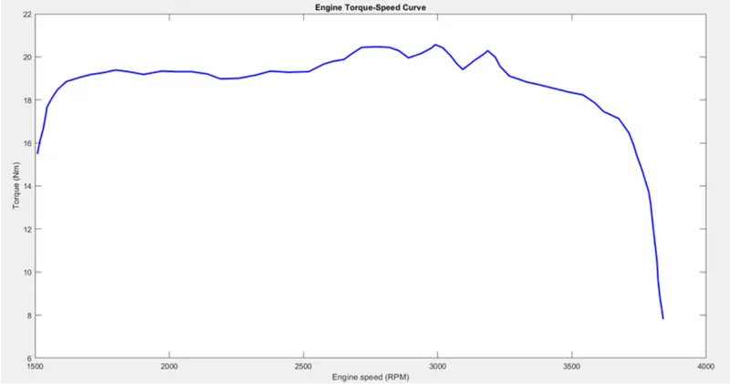
- The engine uses a programmed relationship between speed and torque, modulated by the throttle signal. The throttle input is seen above(fed into port T) and the speed-torque data points are extracted from the graph shown below and fed into the engine through creation of column vectors in MATLAB.
- Crankshaft(PortF) is connected to an engine sensor, which simply senses the angular velocity and angular displacement of the Crankshaft.
- The simple gear between engine and CVT gear box is to slow down the engine RPM before it is fed to the CVT. An appropriate gear ratio needs to be selected so that over or under reviewing isn't an issue.
Continuously Variable Transmission(CVT):
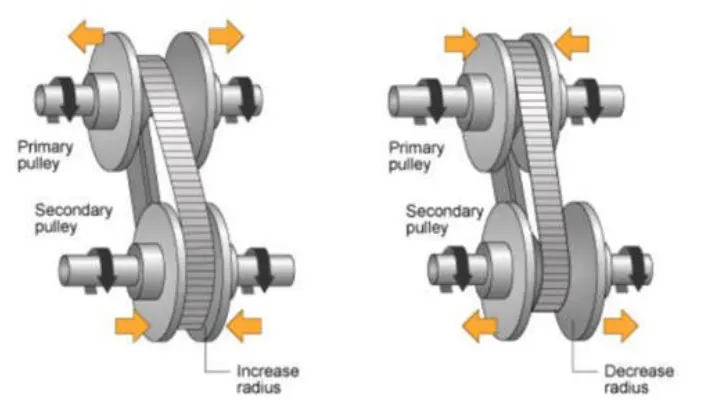
- As evident in this, above two cone-shaped pulleys connected by a steel or composite belt,whose diameter are continuously variable, work together to provide infinite gear ratios.
- Optimizing engine speed in a variety of road conditions, according to the speed and torque requirement of the terrain.
- Differ from automatic transmission in the sense that there are not gear the vehicles needs to step up/down to for the different speed/torque requirement. Similar to automatic transmissin in the sense that the gear are shifted automatically.
CVT Subsystem block:
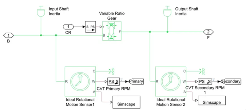
- The input and output shaft inertia represent primary pulley(driver) and secondary pulley (driven) respectively.
- The Variable ratio gear block represents the multiple gears of the CVT, with the gear ratio input given to Port R(Shown below)
- Two rotational motion sensor are for tracking the angular velocities of the two pulleys.
Vehicle body subsystem block:
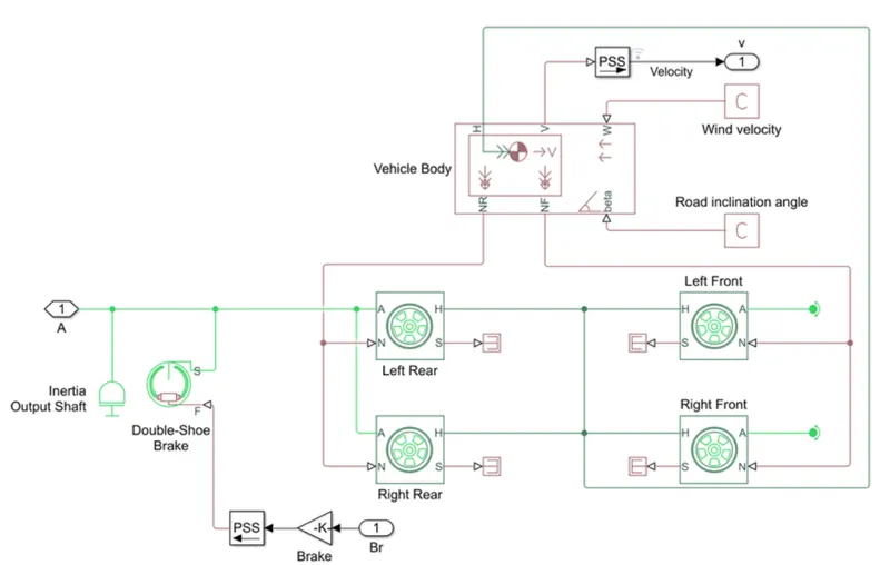
- The Vehicle Body accounts for body mass, aerodynamic drag, road incline and weight distribution between axles due to acceleration and road profile.
- The Double-Shoe Brake is to apply brakes to the rear wheels. With this component, two brake blocks are applied at opposite ends of the drum. This prevents an unbalanced force from acting on the shaft and bearing connecting the drum to the wheel, Which would be the case with a Single-Shoe brake.
- All of the above is applied to the four wheels
Vehicle speed output based on throttle and brake signals:
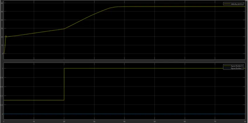
- There is constant acceleration at throttle of 0.3 from 0 to 20 Seconds
- After 20 seconds the car accelerates until peak velocity as throttle hits a max value of 1.
CVT Shaft speed output based on CVT gear ratio input:
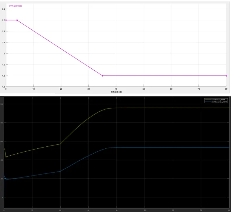
The CVT gear ratio input is above 1 throughout, Which is why we see a lower secondary RPM than primary, because the output shaft will rotate slower to provide more torque to the wheels.
Varying CVT gear ratio:
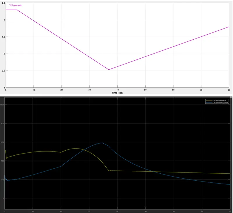
As soon as the CVT gear ratio falls below 1( at about 28sec), the Secondary RPM becomes higher than the primary RPM as the velocity of the vehicle also increases with the reduction in torque.
case 2:
SIMULINK MODEL FOR BAJA ATV WITH CVT and Dashboard:
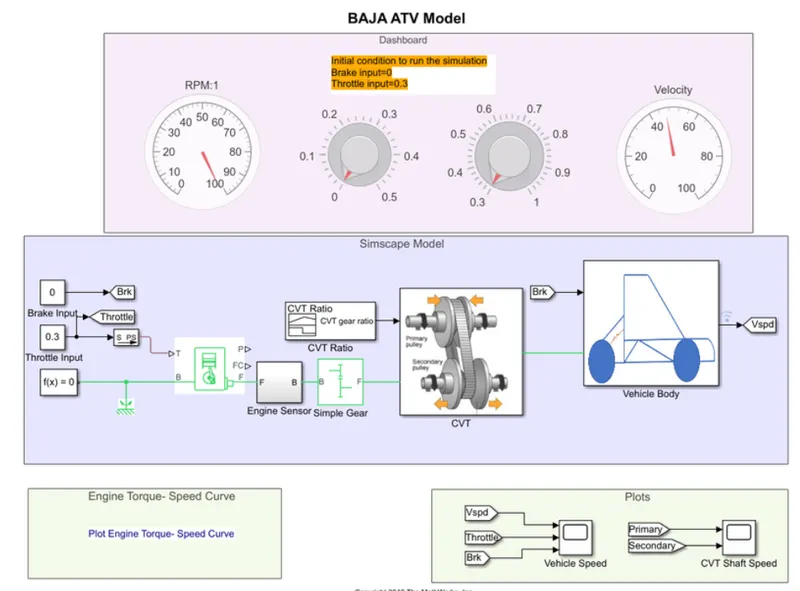
The only difference between Study1 case-1 and case-2 is that the throttle and brake inputs are given via graphical representation (dashboard contro knobs) blocks while the simulation is running for an indefinite period. This allows us to input various scenarios.
Study 2:
SIMULINK MODEL FOR BAJA ATV WITH LOOKUP TABLE:
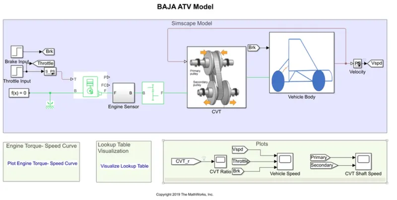
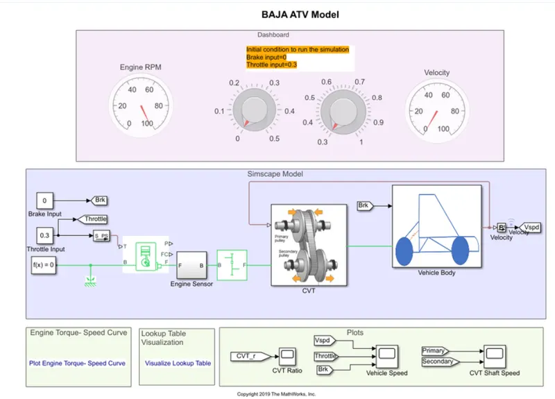
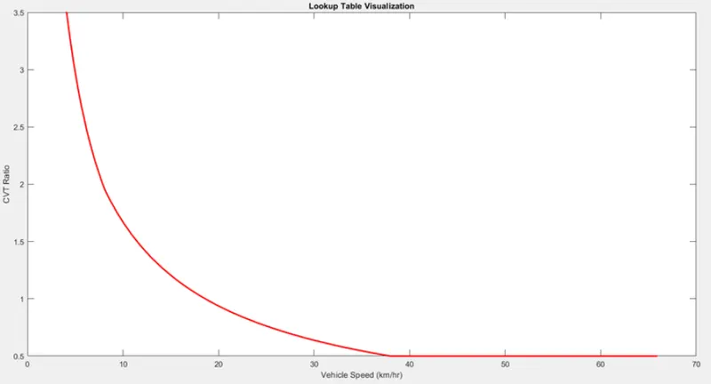
- The only difference with study is that the CVT gear ratio is not fed in via a signal builder, but instead via a Lookup table.
- This Lookup table is data regarding the relation between CVT gear ratio and vehicle speed, which is incorporated through a simple MATLAB script.
- In Study2, a CVT gear ratio had to be inputted manually to see the effect on the vehicle's velocity.However this is not feasible in reality and does not mimic happens in real time.Through this lookup table, the CVT can be modeled based on the Vehicle speed as feedback is taken from vehicle velocity to calculate gear ratio.
Conclusion:
The BAJA ATV with CVT was modelled using two main studies.With the focus purely on CVT, this project is able to show the effect of CVT on vehicle Velocity, although multiple situations for different models of ATV design.