Project 2 - Modeling of 3 phase Induction Motor Drive
Project 2
Modeling of 3 phase Induction Motor Drive
EV REFRESHER
This project is focused towards electric vehicle application using an Induction Motor. Student will have to take following steps for a successful model:
- Model 3 Phase Inverter using Simulink (model the parasitic as well) with a switching frequency of 10Khz using 3 phase Squirrel Cage Induction motor, using V/F method, open loop
Design Parameters:
- Power = 100 HP
- DC Voltage = 800 V
- Output Voltage = 460 VRMS – line to line
- Initial Speed = 1500 RPM
- Final Speed = 1000 RPM
- Initial Load Torque = 10 Nm
- Final Torque=20 Nm
- Torque Step Time = 0.1 secs
For Induction Motor model – use Asynchronous Machine from Simulink with Squirrel Cage Preset Model – 05 , for 100HP Motor
For back emf to speed relation, assume a linear rate from 0.25 to 1, with speed changing from 500 RPM to 2000 RPM
Plot speed, stator voltage (line to line) and frequency.
Plot stator line voltage, phase current
- Use the 3 phase inductor motor theory to derive the transfer function of 3 phase Induction Motor
- Model 3 phase induction motor with a 3 phase inverter using Direct Torque control using an Average Model, Implement both torque and flux control to achieve desired power.
Design Parameters:
- Initial Speed = 0 RPM
- Flux Target = 2.5 webers
- DC Voltage = 500 V;
- Fundamental Frequency = 60 Hz
- Speed Step Time = 0.01 secs
- Determine fundamental speed based upon fundamental frequency
- Determine the switching sequence for direct torque control
- Moment of Inertia = 0.1 Kgm^2
- Load Torque Initial = 0 Nm
- Final Load Torque = 50 Nm
- Torque Step Time = 0.03 secs
Motor Parameters: (Create an Average Model)
- Stator Resistance = 0.5 Ohms
- Rotor Resistance = 0.2 Ohms
- Stator Leakage Inductance = 20 mH
- Rotor Leakage Inductance = 10 mH
- Magnetizing Inductance = 200 mH
- Number of Poles = 4
- Torque to Speed
Answer:
- Model 3 Phase Inverter using Simulink (model the parasitic as well) with a switching frequency of 10Khz using 3 phase Squirrel Cage Induction motor, using V/F method, open loop
Design Parameters:
- Power = 100 HP
- DC Voltage = 800 V
- Output Voltage = 460 VRMS – line to line
- Initial Speed = 1500 RPM
- Final Speed = 1000 RPM
- Initial Load Torque = 10 Nm
- Final Torque=20 Nm
- Torque Step Time = 0.1 secs
For Induction Motor model – use Asynchronous Machine from Simulink with Squirrel Cage Preset Model – 05 , for 100HP Motor
For back emf to speed relation, assume a linear rate from 0.25 to 1, with speed changing from 500 RPM to 2000 RPM
Plot speed, stator voltage (line to line) and frequency.
Plot stator line voltage, phase current
SOLUTION:
We will take into account the aforementioned factors when designing the entire model and simulating it in MATLAB Simulink for this project.
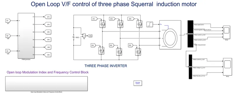
We are using the switch schemes for the 6 IGBTs at 15KHz in this project, the
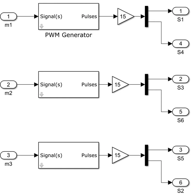
The schematics for switching are displayed below.
PWM GENERATOR:
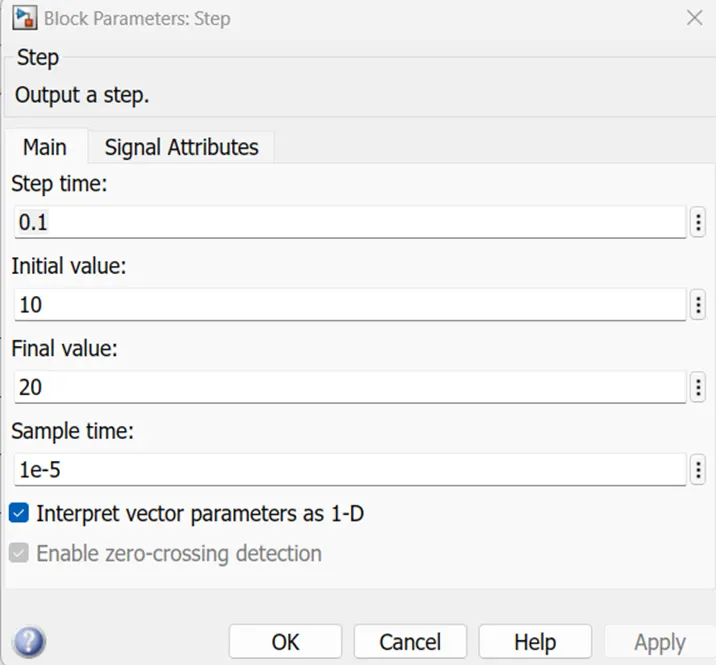
We are using the following torque References:
Initial Load Torque = 10 Nm
Final Torque=20 Nm
Torque Step Time = 0.1 secs
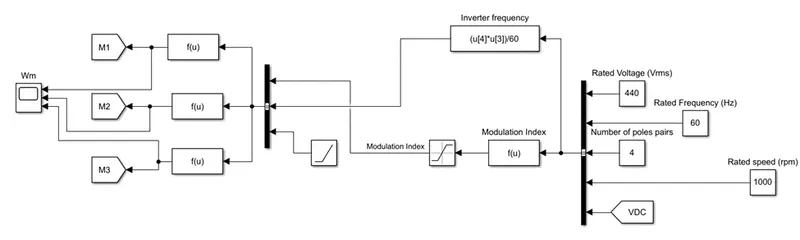
The drive's V/I Control mechanism is also as.
Open loop Modulation Index and Frequency Control Block:
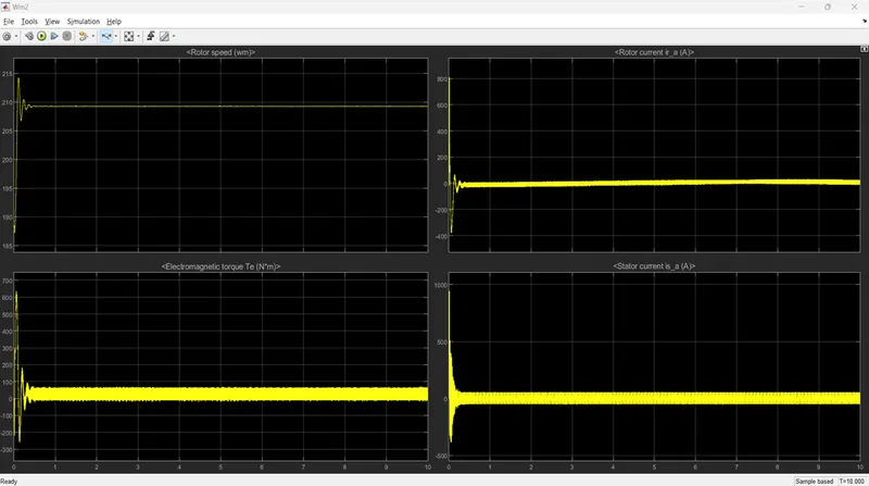
The output waveforms now include rotor speed, rotor current, and
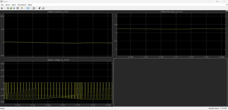
Stator flux, Stator current, and electromagnetic torque
Stator voltage is displayed below.
Part-2
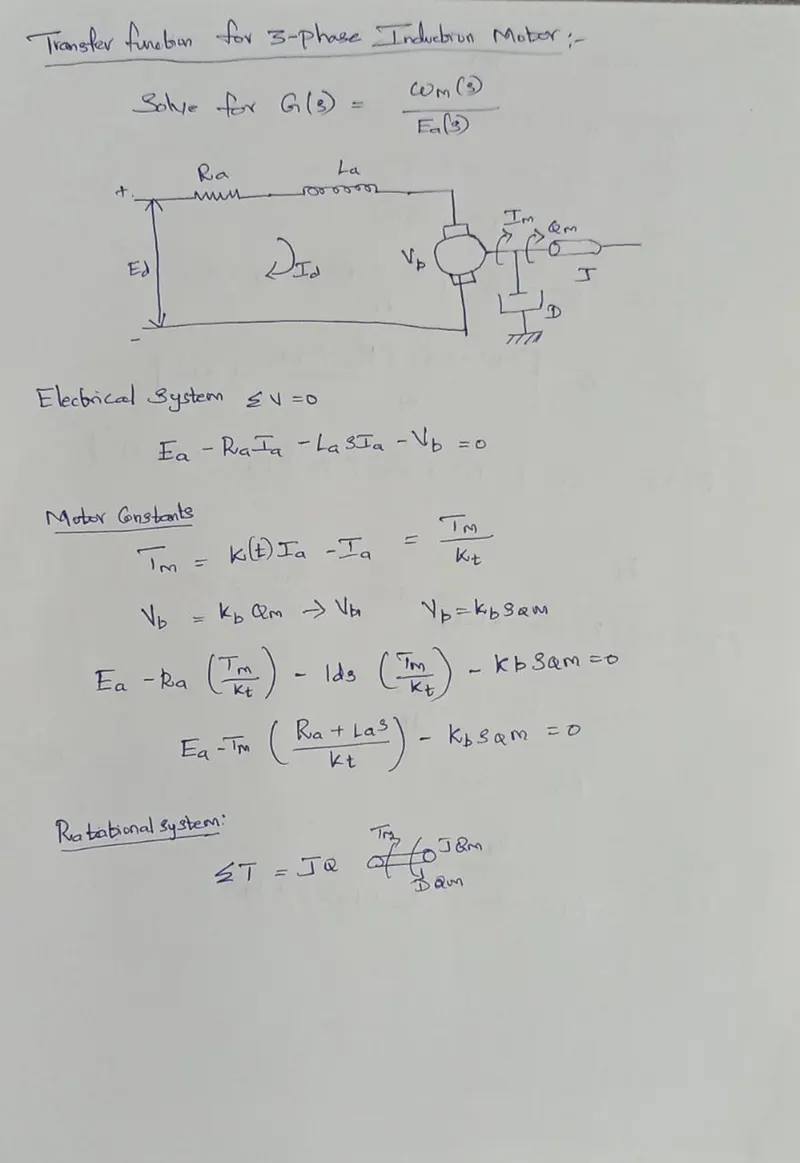
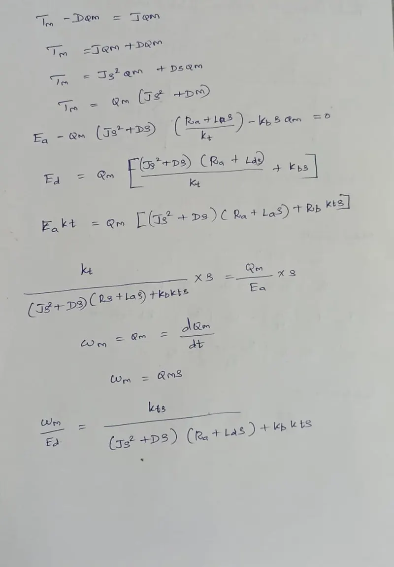
- Use the 3 phase inductor motor theory to derive the transfer function of 3 phase Induction Motor
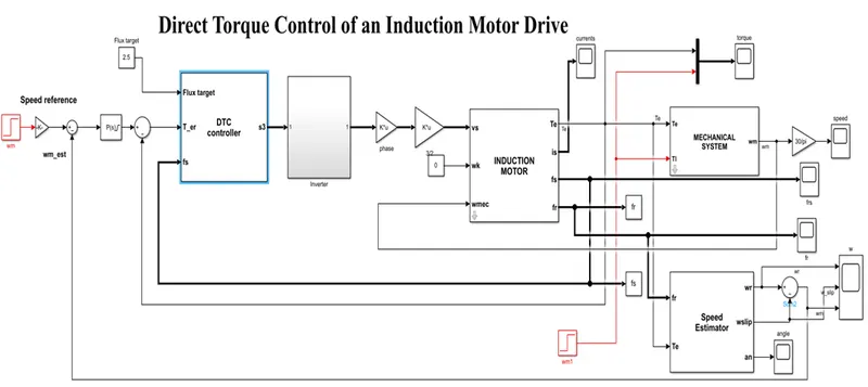
- Model 3 phase induction motor with a 3 phase inverter using Direct Torque control using an Average Model, Implement both torque and flux control to achieve desired power.
Design Parameters:
- Initial Speed = 0 RPM
- Flux Target = 2.5 webers
- DC Voltage = 500 V;
- Fundamental Frequency = 60 Hz
- Speed Step Time = 0.01 secs
- Determine fundamental speed based upon fundamental frequency
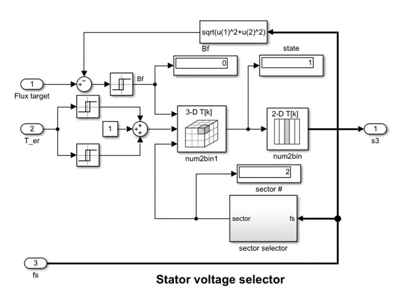
- Determine the switching sequence for direct torque control
- Moment of Inertia = 0.1 Kgm^2
- Load Torque Initial = 0 Nm
- Final Load Torque = 50 Nm
- Torque Step Time = 0.03 secs
Motor Parameters: (Create an Average Model)
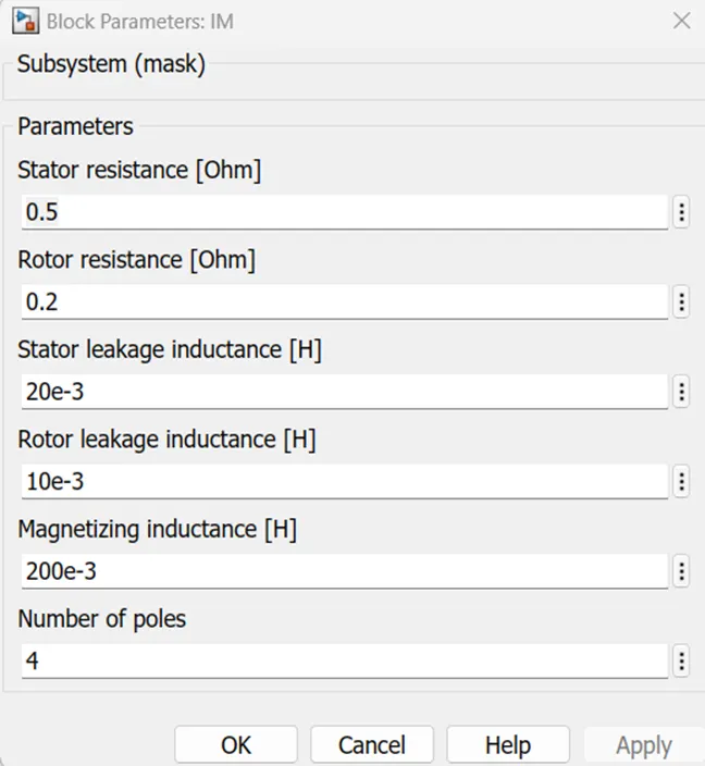
- Stator Resistance = 0.5 Ohms
- Rotor Resistance = 0.2 Ohms
- Stator Leakage Inductance = 20 mH
- Rotor Leakage Inductance = 10 mH
- Magnetizing Inductance = 200 mH
- Number of Poles = 4
- Torque to Speed
Answer:
Stator voltage selector:
Induction Motor Parameters:
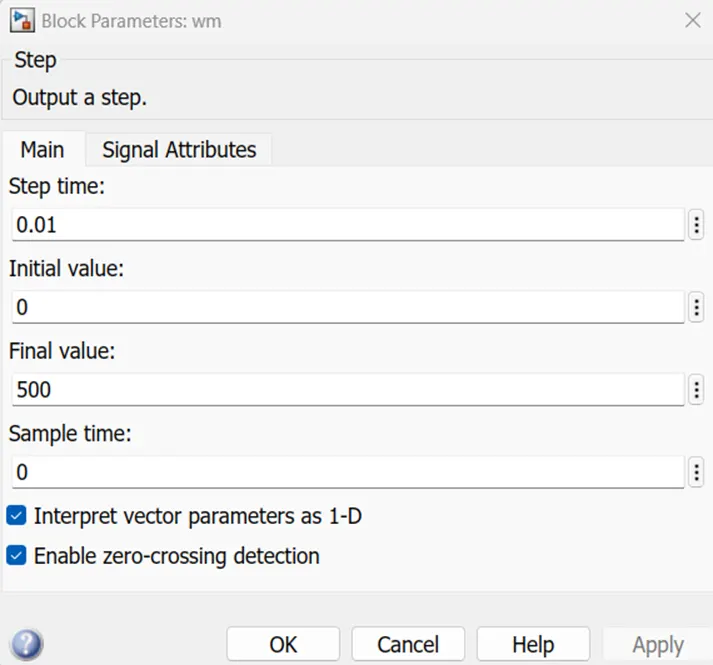
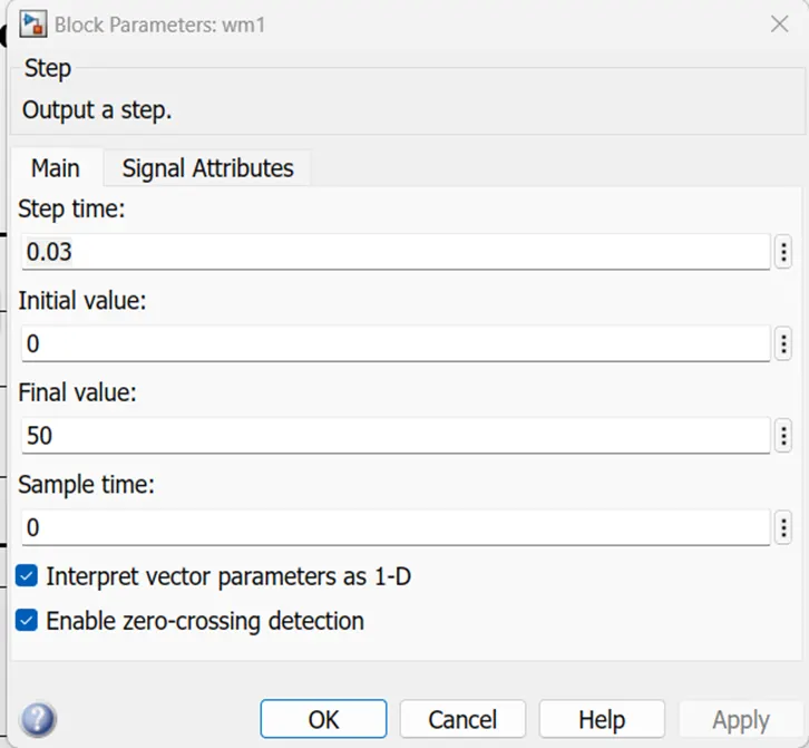
Output Result:
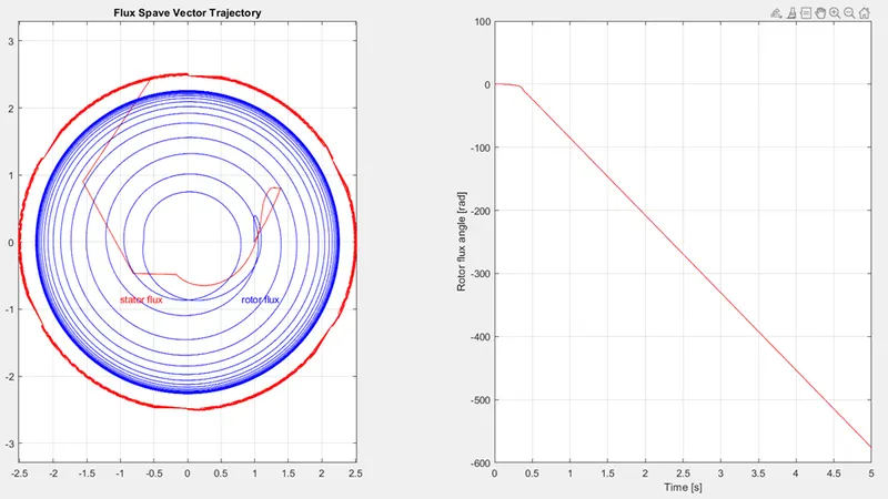
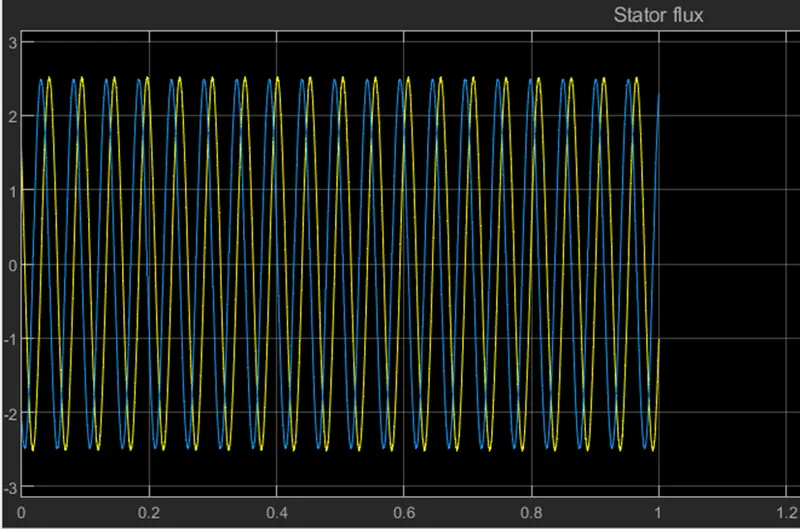
Motor Flux:
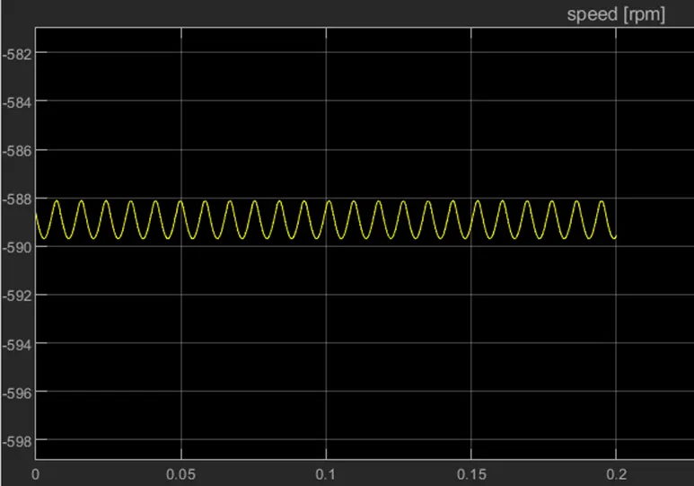
Motor Speed:
Current:
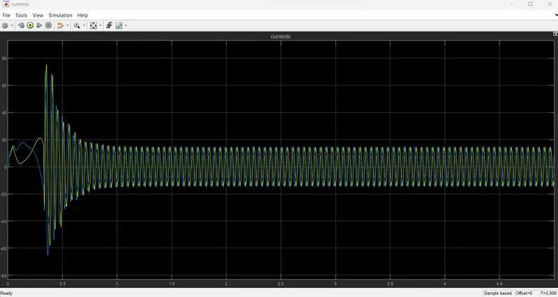
Motor Torque:
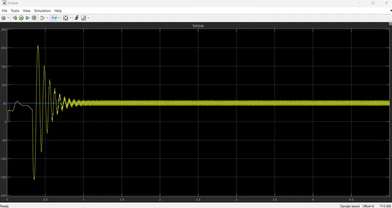
Motor fr:
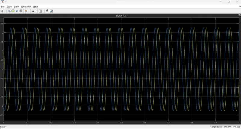
Speed Estimator:
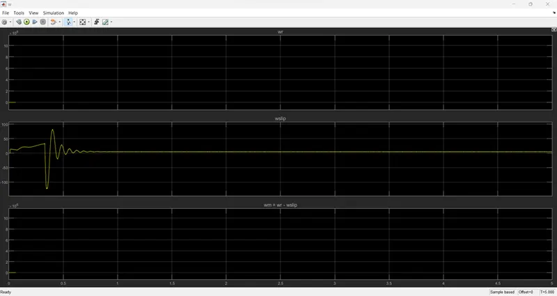
Speed Estimator Flux:
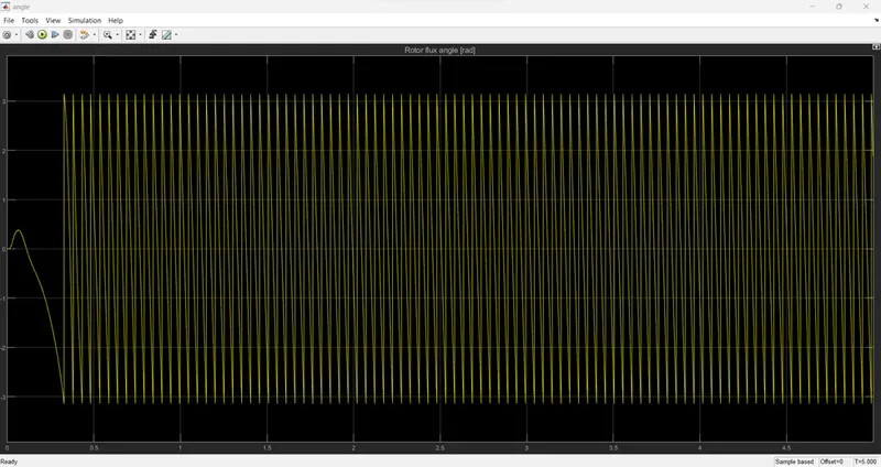
Please see the attachment files below for all of the model files and the PDF of the transfer function.