Week-6 Challenge: EV Drivetrain
WEEK 6 CHALLENGES
EV Drivetrain
- Which types of power converter circuits are employed in electric and hybrid electric vehicle?
Answer:
First of we want to know that what is power Converter.
What is a Power Converter?
An electrical circuit known as a converter accepts a DC input and produces a DC output of a different voltage. This is often accomplished through high frequency switching action using inductive and capacitive filter elements.
An electrical circuit known as a power converter transforms electric energy from one form into the one that is optimal for a given load. A converter's output could be different from the input and perform one or more functions. The computer power supply unit uses it to produce multiple output voltages of the same polarity as the input, different polarities, or mixed polarities. It can also be used to flip polarity and raise or decrease the amplitude of the input voltage.
Between the power source and the power supply output, the converter serves as a connecting point or a step of transformation. Based on the source input voltage and the output voltage, there are various converter types.
The converter uses linear and non-linear reactive components for current and voltage filtering as well as intermediate energy storage, such as semiconductor switches, inductors, transformers, and capacitors. These parts account for a major portion of the converter's size, weight, and price.
The buck, boost, and buck and boost converter circuits are the three fundamental converter types that are frequently employed in DC to DC converters. Due to their simplicity and use of fewer components, these designs are the most used topologies. Each has benefits and disadvantages that decide whether it is suitable for a given application.
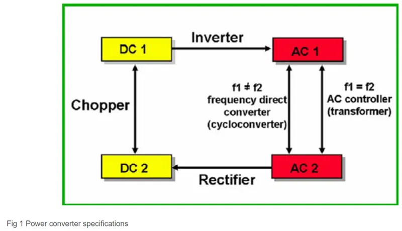
These falls into four categories namely;
- AC to DC converter known as the rectifier,
- AC to AC cyclo converter or frequency changer,
- DC to DC voltage or current converter,
- DC to AC inverter.
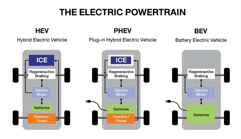
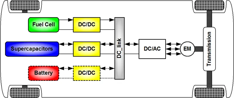
These types of electric Vehicle having the power Train image has showed.
AC to DC converter: (rectifier)
- This kind of converter transforms an AC power source into a DC power source. Our homes receive power from a power plant that is transmitted at 230V and 50Hz, which we may use to run our electrical appliances.
- We require a converter for this application because our appliances run on a DC supply rather than an AC one. Phone chargers, laptop chargers, and other devices are examples of Ac to DC converters.
- An alternating waveform found in an AC power supply frequently reverses direction. An AC to DC converter will stop the current from switching directions, allowing it to flow solely in one direction. A step-down transformer is present in the circuit of an AC to DC converter,
- The step-down transformer reduces the high level 230V from the mains supply to a lesser level, such as 12 or 3V for our usage, while keeping the AC form of the energy. The current is then limited to flow in only one direction using a diode or group of diodes.
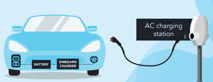
- When it comes to EVs or HEVs, the battery pack, which uses a DC power source, is charged either at home or at a charging station, both of which get power in AC form from the electrical grid. So, a case of an AC to DC power converter would be the chargers for these vehicles.
DC to DC voltage or current converter: (Chopper)
This kind of converter is comparable to a transformer in that it has the ability to transfer voltage from one level to another. Similar to a step up or step down transistor, it can take an input source of voltage and raise it or do the exact opposite and reduce it. A "chopper" is the name for this type of converter. For the safety of the appliance and the user, as well as to supply a specific component with the required amount of power, this kind of converter is used.
It all relies on the load requirements because if a component is supplied with too little or too high voltage, it won't operate due to a shortage of power or it will be damaged.
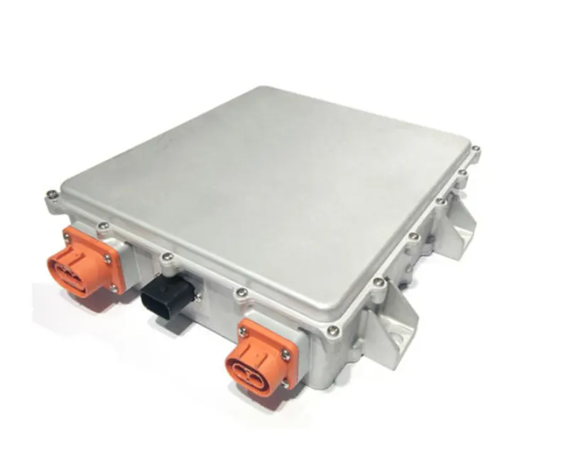
It operates by taking a DC supply and running it through a switching component, which changes the waveform into an AC-like square wave. Then, after going through a filter, this AC is converted back into a DC supply so that it can be used with a load. This sort of converter serves a variety of functions in EVs, HEVs, and conventional automobiles.
For instance, in the case of stepping down the voltage, the car radio may only need a stepped down voltage of 12V and not the entire voltage of the car battery to operate.
There are two basic categories of DC to DC converters:
- Isolated
- Non-isolated type.
Isolated Type:
- Fly back converters are similar to Buck Boost converters, but instead of using an inductor to store energy, they employ transformers.
- Forward converters use transformers to transmit energy from the input to the output in a single step.
Non-isolated Type:
- Buck means to reduce the voltage.
- Boost - increasing voltage
- Buck/Boost - this is mostly used to flip polarity but can also do step up and step-down operations.
DC to AC inverter:
- It converts a DC supply to an AC one. For usage in houses or systems with an AC load, power that is supplied by a battery or capacitor can be converted to the AC type. To use this electricity from the mains, for example, the power produced by solar panels is stored in batteries in the DC form, which can power a house that uses an AC power source. This kind of converter, sometimes known as a "inverter," is frequently used in houses and in EVs and HEVs.
- Using an electronic switch, which is essentially a group of semiconductor transistors like IGBTs and MOSFETs, the DC supply is converted to an AC waveform. To control the direction of current in a circuit, these switches are controlled by a controller to be in either an open or closed position. The controller determines the frequency for the same and sends signals to the switches to tell them to open or close.
- For EVs and HEVs, the inverter will receive its electricity from the battery pack. A transformer with a primary and secondary winding is built within the inverter. The primary winding receives the battery's current first, where electrical switches repeatedly change the current's direction to produce an AC waveform. This current will flip around and go back the way it was.
- The primary winding's AC current will cause the secondary winding's AC current, which will subsequently supply this current to an AC load, such as the AC traction motor.
AC to AC cyclo converter or frequency changer:
This kind of converter produces a distinct AC waveform with a different voltage and frequency from an input AC waveform that has a specific voltage and frequency. Depending on the application, the output voltage and/or frequency can be modified or maintained. There are numerous uses for this converter in daily life, such as controlling motor speed and dimming lamps.
AC to AC converters come in four primary categories
- Cycloconverters
- AC to AC convert with DC Link
- Matrix Converter
- Hybrid Matrix Converter
- An Electric Vehicle's powertrain with 72V battery pack in shown in the diagram below. The duty ratio for acceleration operation is 'd1' and for the braking operation the duty ratio is 'd2'.
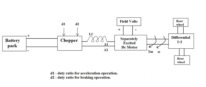
The other parameters of the electric vehicle are given below,
Motor and Controller Parameters:
Rated Armature voltage= 72 V
Rated armature current= 400 A
Ra= 0.5Ω, KΦ= 0.7 Volt second
Chopper Switching frequency= 400 Hz
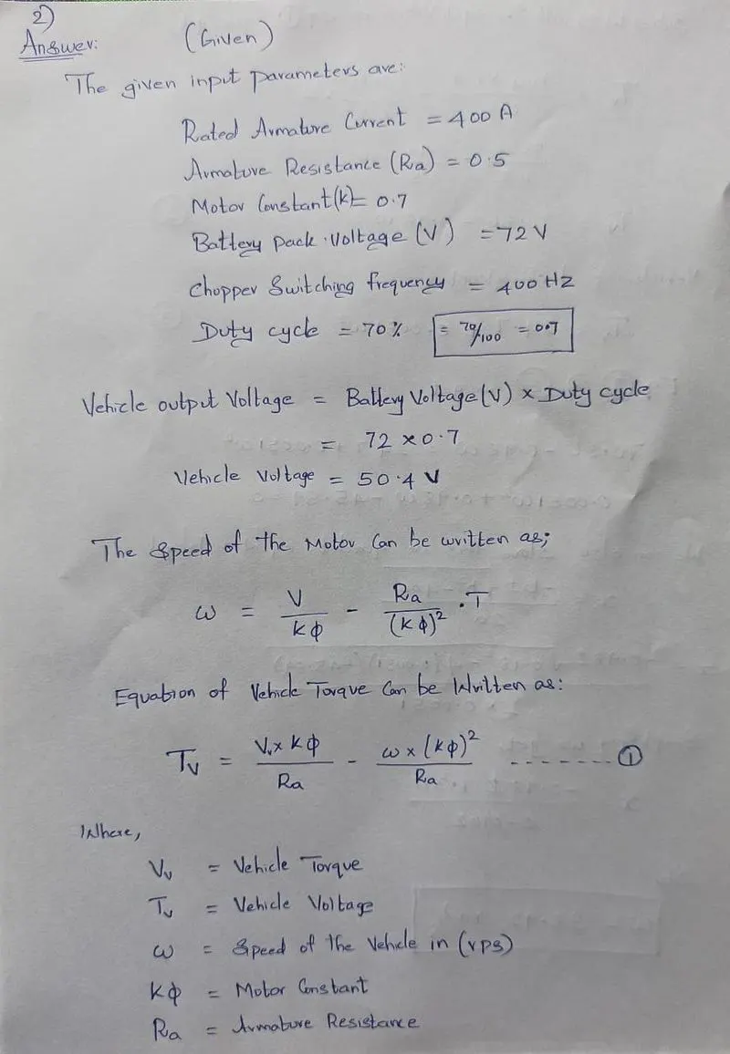
The vehicle speed-torque characteristics are given by the below equation
What is EV steady state speed if duty cycle is 70%?
Answer:

- Develop a mathematical model of a DC Motor for the below equation using Simulink.
ω= V/Kϕ -Ra/Kϕ^2. T
Answer:
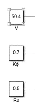
V = 50.4 V
Kϕ =0.7
Ra = 0.5 ohms
Mathematical Model of a DC Motor:
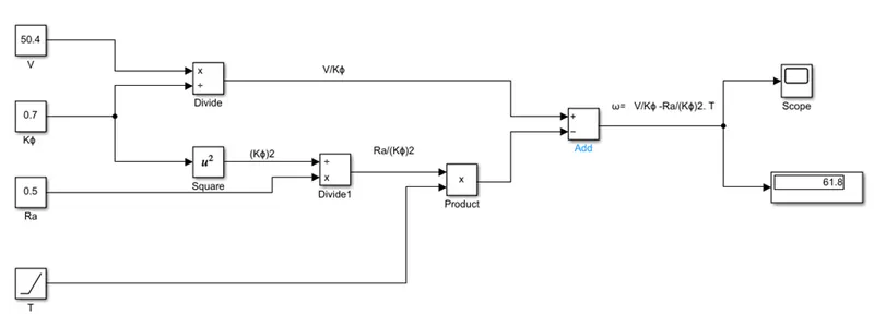
Here the Blocks use are constant as voltage, Motor Constant, Armature Resistance.
For the Torque here we used the Ramp Block:

- First the voltage and the Motor constant is divided by the */ block (Product) V/Kϕ
- Then the motor constant Kϕ is squared by the Square block and by the output coming from the Square block and the Armature resistance the Armature resistance is */ block (Product)
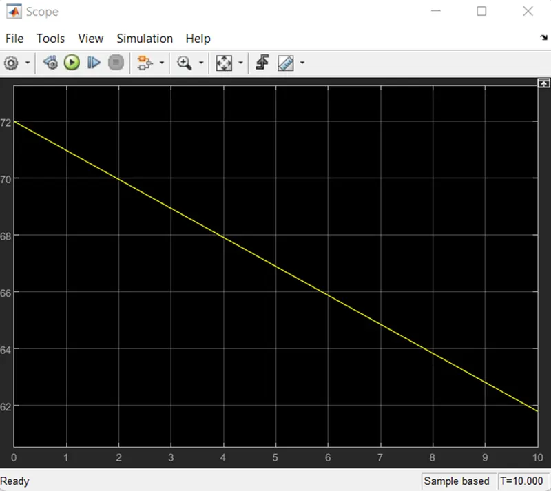
- The ramp block generates the torque the output of Ra/(Kϕ)2 and ‘T’ Is multiplied by the product block
- The final V/Kϕ *Ra/(Kϕ)2. T so we get the output result.
Scope: (OUTPUT)
- Refer to the blog on below topic:
Induction Versus DC brushless motors by Wally Rippel, Tesla
Explain in brief about author’s perspective.
Answer:
EXPLANATION FROM THE PERSPECTIVE OF THE AUTHOR:
- The purpose of the author's blog is to discuss the distinctions between the two motor drives that are most frequently used in the automotive sector: the DC brushless motor drive and the induction motor drive.
Rippel goes into great depth on how the two drive types differ in terms of building, labor, and cost.
However, he has not concluded that one form is superior than the other based on what he has written.
- In the final lines of the first paragraph, Rippel asserts that there is no "one optimal engine type" and that the choice of an engine ultimately boils down to personal opinion.
- He concludes the blog by adding that there is still "no winner when it comes to motor drive selection either" in this similar vein. Despite the similarities between the two types of motor drives, each has advantages and disadvantages.
- For DC Brushless drives, it is stated that two or more permanent magnets are used at the rotor to create a DC magnetic field.
- It also includes a stator core, which is composed of thin, stacked laminations; this means that it cannot be powered by a DC source because it requires frequent changes in the direction of the current to maintain a constant torque.
- For induction drives, the rotor is made of stacked steel laminations with buried peripheral conductors, creating a shorted structure instead of magnets. The revolving magnetic field that interacts with the rotor is produced by the current flowing through the stator windings.
- Induction motors don't need an inverter to start the drive and produce the beginning torque; they can be utilized straight with electricity from the mains.it is capable of starting with the mains load on. DC brushless drives, however, cannot accomplish the same.
- When connected to a mains power supply, they are unable to provide a starting torque. To do this, they require an inverter.
- Induction motor drives are entirely dependent on an AC power supply and cannot operate on a DC power supply.
- In addition, they have a limited beginning torque as well as peak torque when they are linked to a three-phase less supply, and the rotor rotates at a fixed speed.
- An inverter can be used to run the induction drive from a DC power source or a battery in order to correct this.
- The consistent speed is no longer a problem if the inverter frequency is changed; it can then be changed.
- DC Permanent magnets are used in brushless drives, which are unable to modify the strength of their magnetic fields. It would be ideal if they could, as the magnetic field strength should be at its maximum when the rotor requires the maximum torque.
- As a result, the power loss due to heat dissipation is decreased since the inverter and motor currents may be kept to a minimum. To minimize hysteresis and eddy current losses, the magnetic field strength should also be minimal when the needed torque is at its lowest.
- In addition to being relatively expensive ($50 per kilogram), the permanent magnets employed have magnetic fields that are challenging to control when ferromagnetic material is present.
- In contrast, since induction drives don't use permanent magnets, they can adjust the magnetic field's strength. When paired with a smart inverter, this allows them to operate with the least amount of hysteresis and eddy current losses and with the greatest amount of efficiency because the rotor can adjust the magnetic field's strength as needed.
- These losses rise as a DC brushless drive gets bigger, but they do not increase if the size of the induction drive also increases. Induction drives are therefore more affordable than DC brushless drives.
DC Brushless drives do, however, produce less heat at the rotors. Rotors spin more readily and efficiently at greater peak points than induction drives.
- In addition, whereas induction drives may function up to a power factor of roughly 85%, DC brushless motors can operate at unity power factor, i.e.
- As a conclusion, Rippel has outlined the several factors that may be used to compare the induction and DC brushless motor drives, as well as the benefits and drawbacks of each.
- As was previously stated, it ultimately depends on the user's preferences.
- The induction drive would be better suited for those needs if a customer is looking for excellent performance at comparably lower costs. But if a user wants high peak point efficiency, high power factor, and simpler control, the DC brushless drive would be a better option. Both kinds have a role in the automotive industry and will continue to be relevant for the applications that each kind is best suited for.
In order to have the best of both drives, Rippel thinks that due to improving vehicle performance, both may be employed side by side under the hood of a car in the future. This would lead to a brand-new type of hybrid that blends the traits of a sports car with those of a regular vehicle, such a sedan.
Conclusion:
Thus, for the given the Question. answer has solved successfully.
References:
https://www.empcasting.com/electric-vehicle-ac-dc/dc-dc-converters-%28housing%29.html