Week-7 Challenge: DC Motor Control
Week-7 Challenge
DC Motor Control
- A. Explain a MATLAB demo model named ‘Speed control of a DC motor using BJT H-bridge’.
- B) Comment on the armature current shoot-up from the scope results.
- C) Refer to the help section of ‘The Four-Quadrant Chopper DC Drive (DC7) block’. Compare it with the H-bridge model.
- (A)
Explain a MATLAB demo model named ‘Speed control of a DC motor using BJT H-bridge’.
Answer:
BJT : (Bipolar Junction Transistor)
A three-terminal bipolar junction transistor is a semiconductor component that has two p-n junctions that can amplify or magnify a signal. It is a device that is current-controlled. The base, collector, and emitter are the three terminals on a BJT. A signal of modest amplitude applied to the transistor's base is available at the collector in amplified form. This is the amplification that the BJT offers. Keep in mind that the amplification procedure does require an external source of DC power supply.
The BJT device can be modelled using the IGBT block.
The gate current controlling the BJT or IGBT is not simulated by the IGBT block. A Simulink® signal (1/0) is used to control the switch. DC motor employs pre-set model (5 HP 24V 1750 rpm). It simulates the load of a fan (where Load torque is proportional to square of speed). When the duty cycle (given in the Pulse Generator block) is changed from 0 to 100 percent, the armature mean voltage can be changed from 0 to 240 V.
H- Bridge:
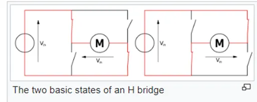
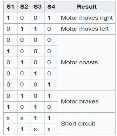
This type of circuit is where the term "H-bridge" originates. Four switches are used to construct an H-bridge (solid-state or mechanical). A positive voltage is applied across the motor when the switches S1 and S4 (seen in the first figure) are closed (and S2 and S3 are open). This voltage is switched around by opening S1 and S4 switches and closing S2 and S3 switches, allowing the motor to run in the opposite direction.
The H-bridge configuration is typically used to switch the motor's polarity or direction, but it can also be used to 'brake' the motor, bringing it to a quick stop by shorting the motor's terminals.
Construction of Bipolar Junction Transistor:
- Bipolar transistors are manufactured in two types, PNPand NPN.
Operation of Bipolar Junction Transistor:
A bipolar junction transistor has three functional areas:
- Active region: The area where transistors function as amplifiers.
- Saturation region:When the transistor is completely on and acting as a switch, and the collector current equals the saturation current.
- Cut-off region:The area where the transistor is completely off and the collector current is zero.
Types of Bipolar Junction Transistor:
- PNP bipolar junction transistor
- NPN bipolar junction transistor
Here we used NPN Transistor
NPN BJT:
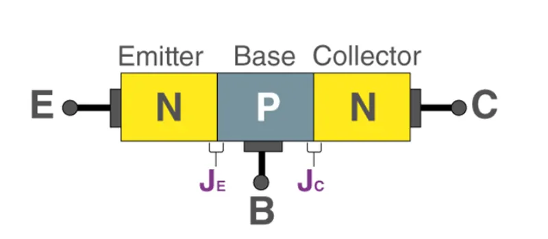
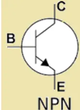
In NPN BJT, p-type semiconductor is sandwiched between the two n-type semiconductors. The two n-type semiconductors act as emitter and collector respectively while the p-type semiconductor acts as a base. This is shown in the figure below.
The operating regions of BJT are:
- Forward active or active region
- Reverse active or inverted region
- Saturation
- Cut-off
From the given question we have to open the Speed control of a DC motor using BJT H in the search bar
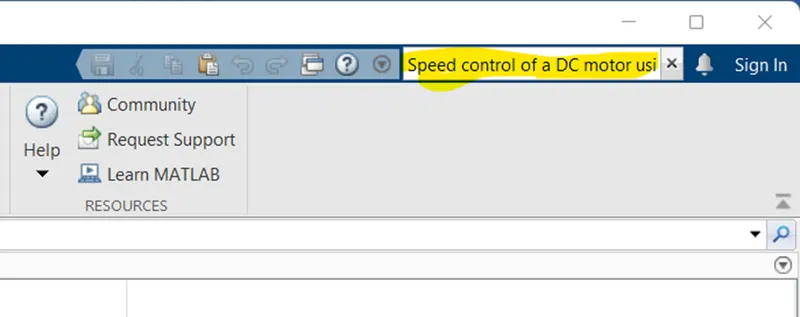
After press enter it search and opened click on the particular model and Select open.
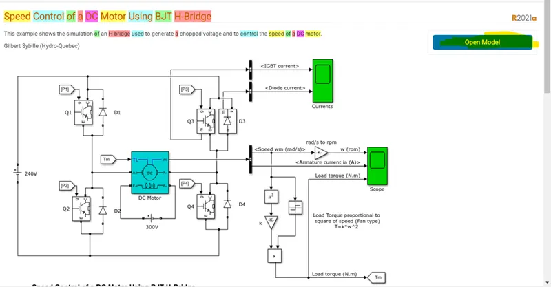
MATLAB Simulink model is now opened look like this,
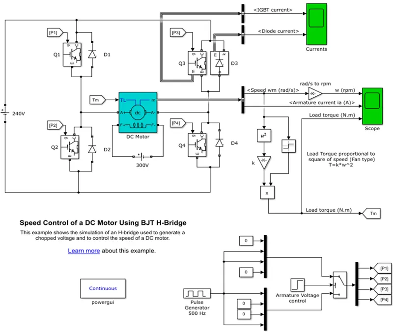
The gate current controlling the BJT or IGBT is not simulated by the IGBT block. A Simulink signal (1/0) is used to control the switch. DC motor employs pre-set model (5 HP 24V 1750 rpm).
It simulates the load of a fan (where Load torque is proportional to square of speed). When the duty cycle (given in the Pulse Generator block) is changed from 0 to 100%, the armature mean voltage can be changed from 0 to 240 V.
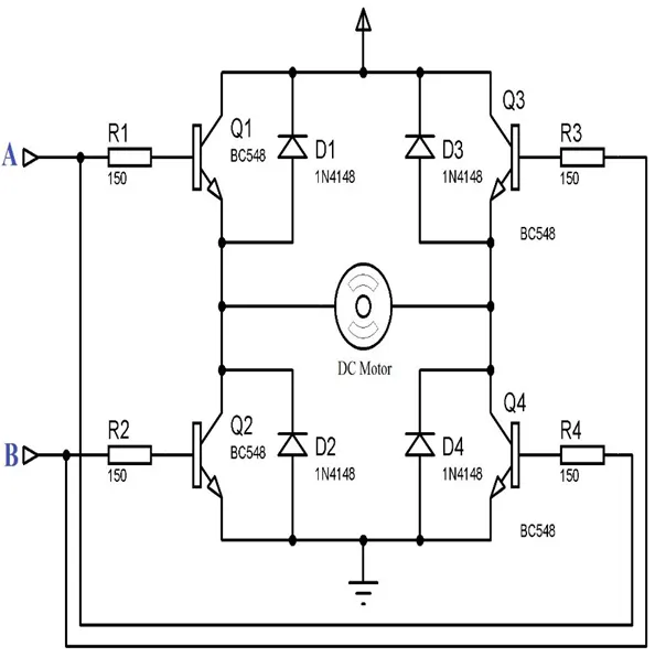
There are four BJT/Diode pairings in the H-bridge (BJT simulated by IGBT models):
The simultaneous switching of Q1 and Q4 or Q2 and Q3 involves two transistors.
- The motor receives a positive voltage when Q1 and Q4 are illuminated.
- The diodes D2-D3 operate as free-wheeling diodes when Q1 and Q4 are off.
- The motor receives a negative voltage when Q2 and Q3 are illuminated.
- The diodes D1–D4 act as free-wheeling diodes when Q2 and Q3 are off.
From the above diagram of the Speed control of a DC motor using BJT H-bridge, contains 4 IGBT (Q1, Q2, Q3, Q4), Four Diode (D1, D2, D3, D4).
In the Simulink block of the DC Motor parameters are set as:
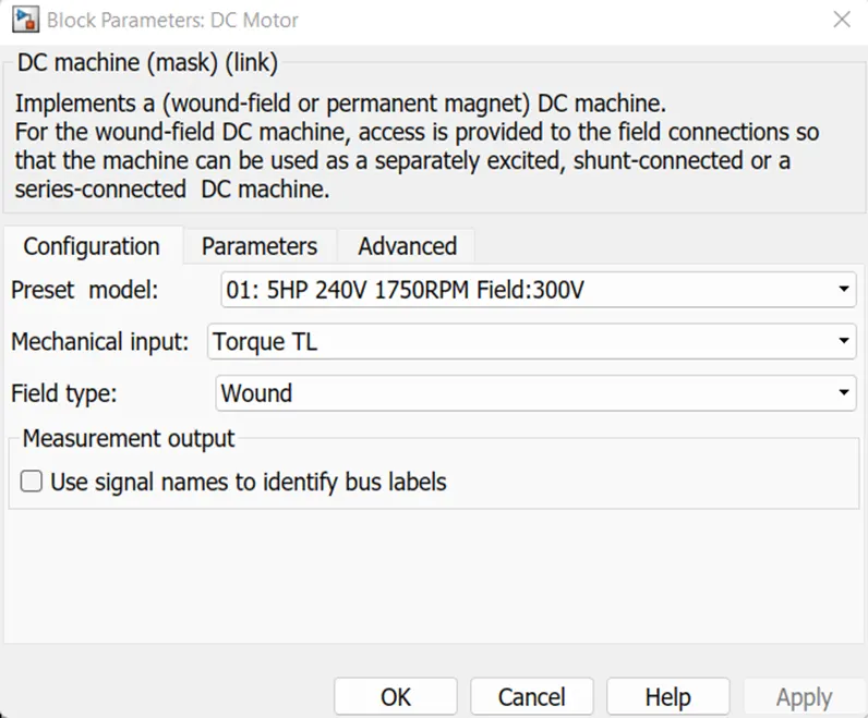
Here the Wound field type is selected and the Mechanical input is the Torque Load.
B.) Comment on the armature current shoot-up from the scope results.
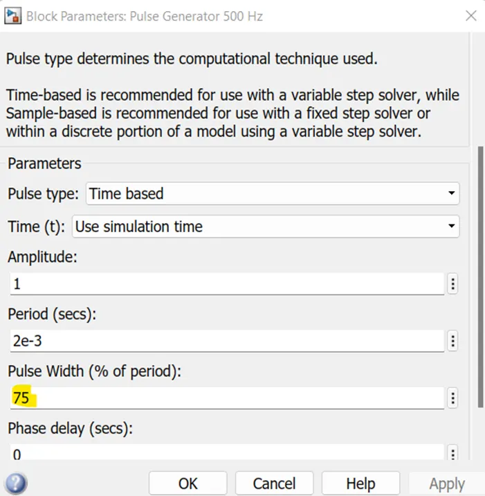
Here the Duty Cycle of the Pulse Generator Block is 75%
Scope: Output
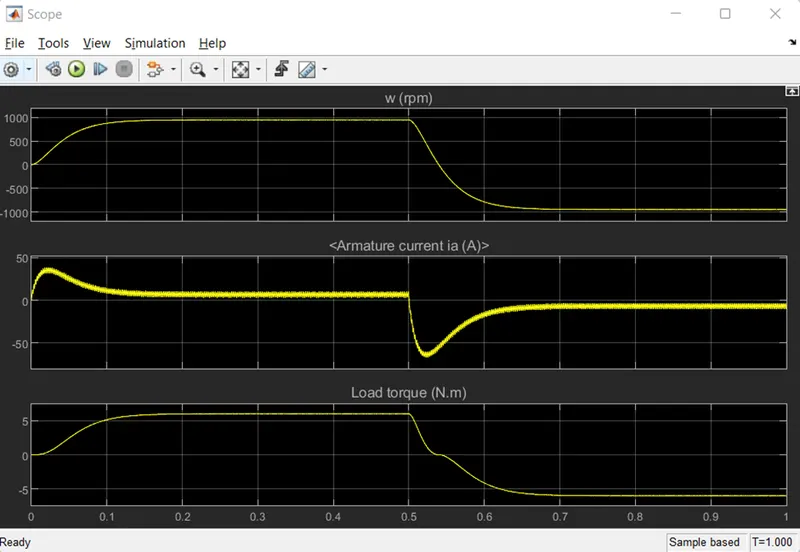
- From the Output we observed that the Speed of the Maximum speed of the motor reaches the 950 Rpm in the forward direction (Positive Cycle). After the step time 0.5 sec the motor rotates in the negative direction, where the Q2 & Q3 start conducting
- The load maximum torque reaches 6.2 (N.m) in the positive cycle and in the case of the negative duration it is -6.2 N.m
- When a motor transitions from forward to reverse, the armature current shoots up by around 68A, which is too much. In order to lessen the current shoot up, we must vary the mode, which may be done by altering the Duty cycles. The DC motor uses torque proportionate to the square of speed to calculate load torque and obtain speed and armature current. A quick shoot-up in act occurs at the beginning.
- This scope demonstrates how speed increases over a specific time period, and how at that point, armature current is positive while load torque also increases. After 0.5 seconds, the pulse generator acts suddenly to increase the speed while decreasing the time period. At this point, the armature current is in the negative terminal while the torque is acting in reverse. In this instance, the abrupt shoot-up occurs as armature current is handled at positive and negative terminals.
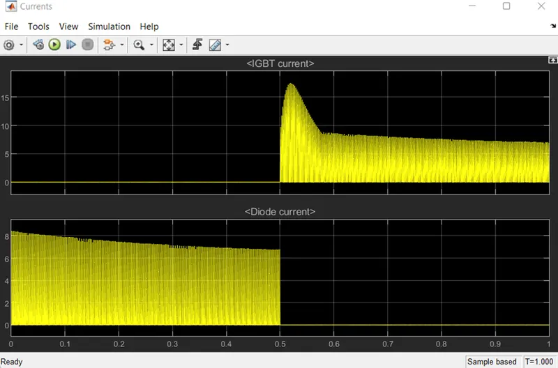
Diode Current and the IGBT Current these are taken from the point of the Emitter.
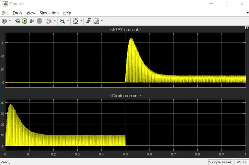
Changing the Pulse Width as 50% and observing the result:
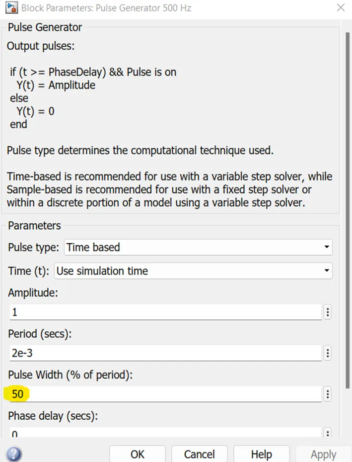
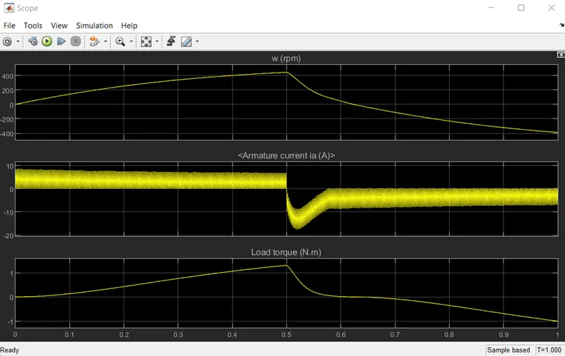
- In this instance, we can see that a comparison with 75 of the pulse width does not explain the abrupt increase. This experiment likewise uses the same cycle time. In the present experiment, the initial current is produced as a diode current for 0.5 seconds, after which the IGBT current is applied while the diode current is being halted.
This graph illustrates the initial stage of current flow when the switch Q3 is OFF and the diode current is ON. D3 switch is ON for the 0.5 seconds that the pulse generator specifies, and it is OFF for the remainder of that time. After 0.5 seconds, an IGBT current is initiated, and the Q3 switch is left on.
- The flow of the armature current and the torque produced by the speed load are both shown in the aforementioned scope.
According to the results, voltage fluctuation is maintained at the starting point of the forwarding and reversing states after a change in pulse width of 50% from the pulse generator. In this experiment, the input supply's pulse width is decreased to lessen the abrupt variation. Similar to the previous Duty cycle, a time period for forward and backward motion is maintained. In this observation, the shot up is lessened compared to the pulse width of 75% when the motor transitions from forward to reverse.
C.) Refer to the help section of ‘The Four-Quadrant Chopper DC Drive (DC7) block’. Compare it with the H-bridge model.
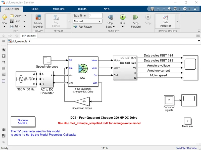
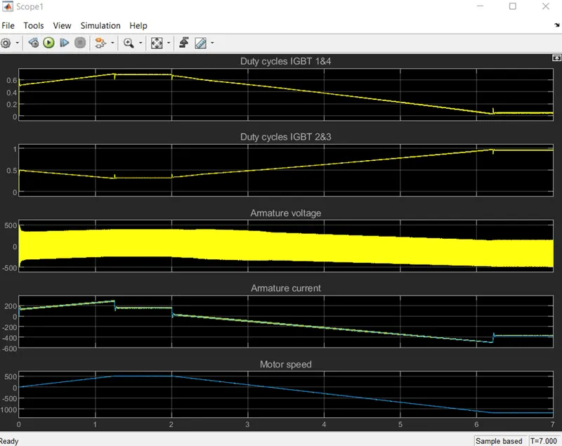
A steady 150 V DC field voltage source is used to individually excite the 200 HP DC motor. An IGBT converter is used to supply the armature voltage, and it is managed by two Pl regulators. A 380 V AC 50 Hz voltage supply is rectified to produce a 515 V DC bus, which is used to power the converter. A brake chopper has been installed between the diode rectifier and the DC7 block to limit the DC bus voltage while in dynamic braking mode.
A speed regulator is the first regulator, and then a current regulator comes next. that the speed regulator outputs. In order to prevent abrupt reference changes that can result in armature over-current and destabilize the system, the speed reference change rate follows acceleration and deceleration ramps.
By calculating the proper duty ratios of the five kHz pulses from the four IGBT devices, the current regulator regulates the armature current (Pulse Width Modulation). The instantaneous pulse values of IGBT devices I and 4 must be opposite those of IGBT devices 2 and 3 in order for the system to function properly. As a result, the average armature voltage required to produce the appropriate armature current is produced. A smoothing inductance is connected in series with the armature circuit to reduce the magnitude of the current oscillations.
Output:
Operation in the first quadrant:
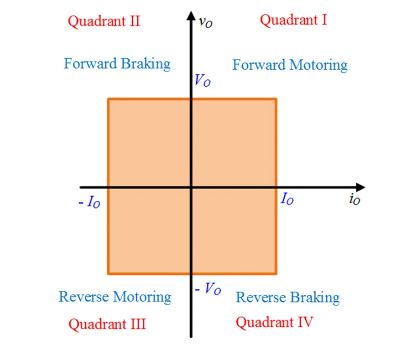
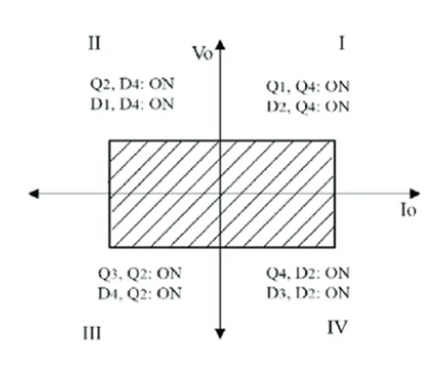
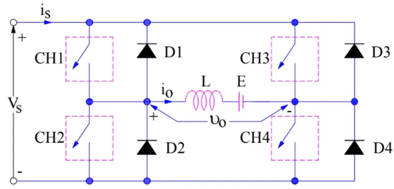
CH4 is left ON, CH3 is left OFF, and CH1 is operated for the first quadrant operation. When both CH1 and CH4 are turned ON at the same time, the load is directly linked to the source, causing the output voltage to match the source voltage.
This basically indicates that vo = vs. The direction of io indicates that the load current flows from source to load. The load current freely circulates via CH4 and D2 when CH1 is switched OFF. Both the voltage and current at the load stay positive during this time. As a result, the output voltage vs and load current io are both positive, and the chopper is therefore operating in the first quadrant. It should be emphasized that the Class-E helicopter in this situation functions as a step-down chopper.
Operation in the Second quadrant:
By operating CH2 while leaving CH1, CH3, and CH4 off, the second quadrant can be operated. Current flows through CH2, D4, E, and L when CH2 is ON because of the DC source in the load. During the On phase of CH2, Inductor L accumulates energy.
Through D1, D4, current is sent back to the source when CH2 is switched OFF. The source voltage Vs is greater than (E+Ldi/dt), which should be noted at this point. It is a second quadrant operation of the chopper because the load voltage Vo is positive and Io is negative.
As a result of the current being fed back to the source, the load is essentially sending power to the source. If you would like a more thorough examination and comprehension, please read Step-up Chopper.
According to the circuit schematic, the load must have emf E in order to operate in the second quadrant. A step-up chopper is how configuration functions in the second quadrant.
Operation in the third quadrant:
Both the load voltage and the load current must be negative in order to operate in the third quadrant. If the direction of the current and voltage matches that of the circuit diagram, they are deemed to be positive. It is negative if the direction is different from what is depicted in the circuit diagram. One crucial point to keep in mind is that third quadrant functioning requires reversing the polarity of the emf E in the load. The circuit diagram for a Class-E chopper operating in the third quadrant is displayed below.
Operation of the third quadrant involves operating CH3, leaving CH2 ON, and turning off CH1. When CH3 is ON, the load connects to the source, making the voltage between the two equal. However, take note that the polarity of the load voltage, vo, is different from what is depicted in the circuit diagram. As a result, vo is taken to be negative. See how the load current IO is doing right now. As can be observed, io is flowing negatively and in the opposite direction from what is depicted in the circuit diagram.
Now that CH3 is off, the negative load current can freely flow through CH2 and D4. In this way, io and vo are both negative. The helicopter thus operates in the third quadrant.
Operation in the Fourth quadrant:
Fourth Quadrant Operation: In order to achieve fourth quadrant operation, CH4 is turned on while CH1, CH2, and CH3 are turned off. In this case, as with the third quadrant operation, the polarity of load emf E must be reversed.
Positive current flows through CH4, D2, L, and E when the CH4 switch is turned on. Inductance L stores energy when CH4 is turned on. When CH4 is turned off, current returns to the source via diodes D2, D3. The load voltage is always negative in this case, but the load current is always positive. This results in helicopter operation in the fourth quadrant. Power is returned to the source from the load, and the chopper functions as a step-up chopper.
Comparing the 4 Quadrant chopper and H-Bridge:
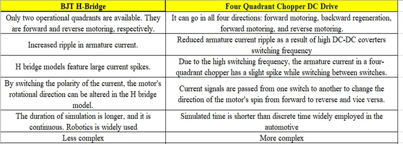
- Develop a 2-quadrant chopper using Simulink & explain the working of the same with the relevant results.
(Refer to article - Multiquadrant operation of motor )
Answer:
Type-C versus Class-C First and second quadrant operation is possible with the category of chopper. This essentially means that with this chopper, electricity can flow either from source to load or load to source. Class-A Two Quadrant Chopper is another name for this type of helicopter.
Operation / Working of Class-C or Type-C Chopper:
Since we already know this, the first and second quadrants are where Class-A and Class-B helicopters operate. As a result, if we connect both of these types of choppers in parallel, we can have choppers operating in both the first and second quadrants.
In actuality, Class-C or Type-C choppers are created by connecting Class-A and Class-B choppers in tandem. This kind of chopper's circuit schematic is shown in the figure below.
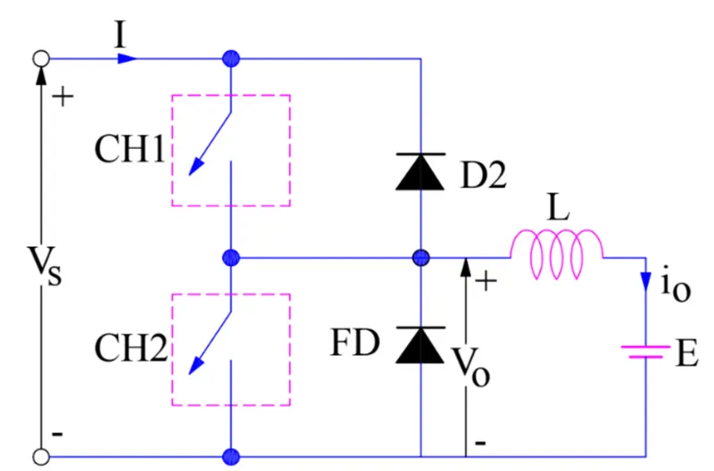
Case-1: When CH1 is switched ON / OFF:
Source Vs becomes connected to the load directly when chopper CH1 is turned ON, making load voltage Vo equal to source voltage. The circuit diagram, which assumes a positive voltage, shows that the load current flows from source to load.
When CH1 is turned OFF, the free-wheeling diode (FD) enters the circuit because it becomes forward biased, shorting the load. As a result, the output voltage Vo drops to zero. The circuit diagram shows that the io continues to decrease through the FD and L in the same manner. As a result, the average output voltage Vo and current Io are positive, indicating that the chopper is operating in the first quadrant. This is actually the Class-B mode of operation.
Case-2: When CH2 is switched ON / OFF:
The load DC source E sends current through CH2 and the load when chopper CH2 is turned ON. Since this current's io direction will be the opposite of what is depicted in the circuit diagram, it is believed to be negative. At this point, Vo, the output voltage, is zero. Diode D2 becomes forward biased when CH2 is turned OFF, which increases the current flowing into the source from the load. When the chopper CH2 is turned off, the load is linked to the source via D2, resulting in an output voltage of Vs at this moment. The operation of the chopper is therefore within the second quadrant because the load current is always negative. This is actually the Class-B mode of operation.
USING THE SIMULINK BLOCK:
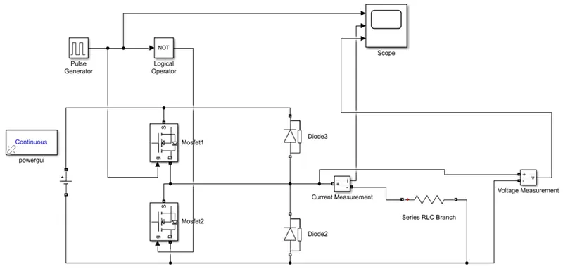
Here the Simulink Model has 2 Mosfet, The one of the Mosfet is connected the Gate point from the Pulse Generator and the another one is form the Pulse Generator to the Logical operator of NOT Operator and connected to the Gate point of the Pulse Generator
The diode prevents the flow of current from load to source. When the chopper is ON, supply voltage VS is applied to the load. i.e. V0 = VS and inductor starts storing energy. At this condition load current raises from Imin to Imax.
One Point of the Current Measurment is Connected to the Scope and the Voltage Measurment Block ‘V’ Point is connected to the Scope.
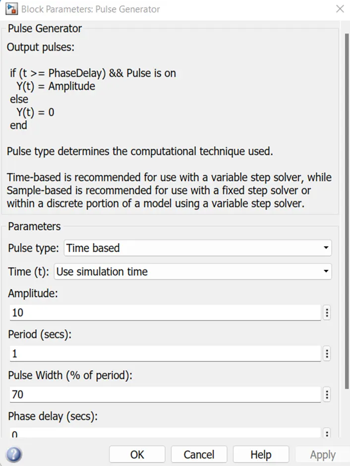
Pulse Generator Block:
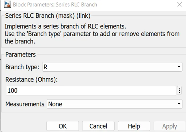
Resistance of the Series RLC Branch, here the Resistance is Selected the value given is 100 Ohms
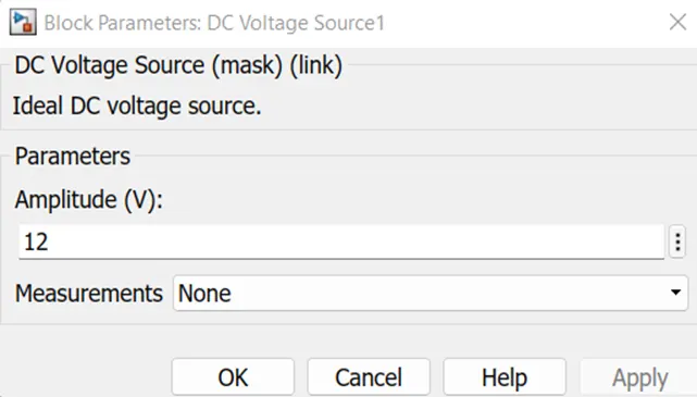
The Given Dc Supply Input is
Output: Scope
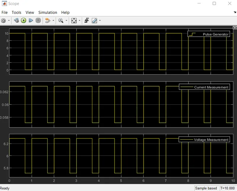
Here the Output is plotted.
3.) Explain in a brief about operation of BLDC motor.
An electronically commutated DC motor without brushes is called a brushless DC motor (also known as a BLDC motor or BL motor). The synchronous motor's speed and torque are controlled by the controller, which delivers current pulses to the motor windings.
The ability to generate a lot of torque across a wide speed range is a key feature of these motor types. In brushless motors, the issue of connecting electricity to the armature is solved by permanent magnets rotating around a fixed armature. A wide range of capabilities and flexibility are available when using electronics for transportation. They are renowned for their quiet operation and capacity to hold torque while still.
Brushless DC motor Construction:
The rotor is where the permanent magnets are attached in this motor. On the stator are the armature windings, or conductors that convey current. Electrical commutation is the process they employ to transform electrical energy into mechanical energy.
The fundamental design distinction between brushed and brushless motors is the substitution of an electric switch circuit for the mechanical commutator. A BLDC motor is a form of synchronous motor because both the rotor and the stator produce a magnetic field that oscillates at the same frequency.
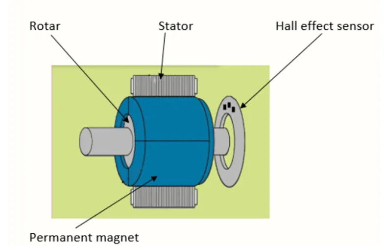
Neither current-carrying commutators nor brushless motors exist. Through an amplifier that is activated by the commutating device, such as an optical encoder, the field within a brushless motor is switched.
The "Up runner" or "In runner" style of a DC brushless motor will affect how it is laid out.
The way a brushless DC motor operates:
Similar to a brushed DC motor, a BLDC motor operates on the same principal. According to the Lorentz force law, a current-carrying conductor experiences a force anytime it is subjected to a magnetic field. The magnet will feel an equal and opposite force as a result of the reaction force. The permanent magnet and current-carrying conductor in the BLDC motor are both stationary.
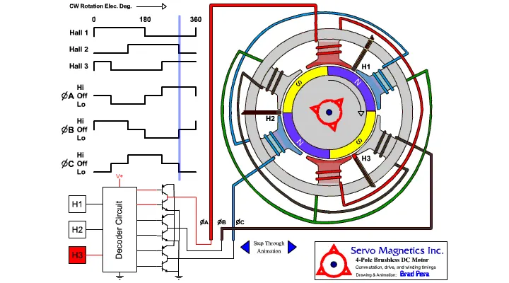
When the stator coils receive power from a source, they become electromagnets and begin to create a consistent magnetic field in the air gap. Despite the supply coming from a DC source, switching causes an AC voltage waveform with a trapezoidal shape to be created. Rotor rotation is maintained by the electromagnet stator's interaction with the permanent magnet stator.
When windings were switched between High and Low signals, the accompanying windings were activated as the North and South poles. The motor rotates as a result of the alignment of the North and South poles of the permanent magnet rotor with the poles of the stator.
Types of Brushless DC Motors:
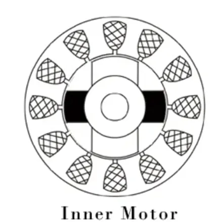
Inner Rotor Design:
The stator windings surround the rotor, which is at the centre of the motor in an inner rotor design. Since the rotor sits inside the core, rotor magnets do not effectively trap internal heat, allowing it to dissipate quickly. For this reason, inner rotor motors create a lot of torque and are effectively used.
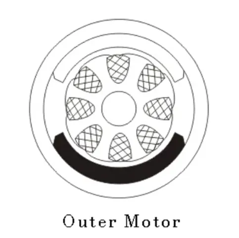
Outer Rotor Design:
In an outer rotor design, the motor's core's winding is encircled by the rotor. The magnets in the rotor trap the motor's heat inside and prevent it from dissipating. Such a motor's design allows it to run at a lower rated current and with less cogging torque.
Advantages of Brushless DC Motor:
- Brushless motors are more effective since their velocity depends on how frequently current is provided rather than how much voltage is applied.
- Owing to the lack of brushes, efficiency is increased as less mechanical energy is lost due to friction.
- Under any circumstance, a BLDC motor can run at high speed.
- During operation, there is hardly any sparking and a lot less noise.
- The stator might use more electromagnets for more precise control.
- Due to the reduced rotor inertia of BLDC motors, they can readily accelerate and decelerate.
- It is a high-performance motor that offers significant torque per cubic inch over a wide range of speeds.
- Due to the lack of brushes, BLDC motors are more dependable, have long life expectancies, and require no maintenance.
Disadvantages of Brushless DC Motors:
- A brushed DC motor is cheaper than a BLDC motor.
- In order to avoid damaging the magnets and winding insulation due to excessive heat, only a limited amount of high power should be applied to BLDC motors.
Conclusion:
Thus for the above questions the answer has solved successfully.
REFRENCES:
https://en.wikipedia.org/wiki/H-bridge/
https://electricalbaba.com/four-quadrant-chopper-or-class-e-chopper/
https://www.pantechsolutions.net/bldc-motor-control
https://www.electrical4u.com/brushless-dc-motors/
https://electricalbaba.com/class-c-or-type-c-chopper-explanation/