Week - 4
WEEK 4 CHALLENGE
AIM:
Implement control logic of a “washing machine” using State flow as per given sequence:
- If the power supply is available, the system gets activated
- If the Water supply is not available, stop the process & indicate through LED
- Soaking time should be 200s followed by Washing time of 100s.
- Then rinsing happens for next 20s & dryer runs for 50s
After all the processes have completed turn on the finished LED.
Answer:
Washing Machine:
A washing machine is a device that allows you to wash a variety of garments without exerting any physical effort. You don't have to rub or squeeze the clothing to remove the water from them when you use a washing machine. A clothes washer, or simply a washer, is another name for a washing machine. You can use the washing machine to wash your clothing automatically without having to watch it. Simply put the garments in the washing machine and pick the wash mode. The washing machine automatically measures the amount of water and detergent needed, as well as the time for washing, rinsing, and drying, based on the selected mode and the number of garments.
SOAKING:
It is a method of removing dirt from garments by dipping them in detergent water. Customers must choose soak from a panel in this function. Soak - With the wash timer is set.
WASHING:
A huge plastic agitator (green) spins around during the wash cycle, propelling your garments through the water. When the wash is finished, the water in the outer drum is drained by the pump.
RINSING:
The unclean, soapy water is emptied, then the washing machine is refilled with clean water and your garments are "rewashed." Spin: After all of the water has been emptied, your clothing is spun very quickly and the excess water is removed using drain pump
DRYER:
They function by blowing heated dry air through wet laundry to extract moisture, then cooling the now humid air in a heat exchanger to condense the moisture, which is either collected in a tank or drained down the drain. The cycle is repeated by reheating the (now dry) air.
Block Used:
Chart:
An event-driven (reactive) system is represented by a finite state machine. When an event occurs in an event-driven system, the system responds by making a transition. A transition from one state (mode) to another If the condition specifying the change is true, this transition occurs.
Constant:
Use this block to provide a constant signal input. Constant block generates a real or complex constant value signal.
Display:
This play role in the display the input Signal we have given, for numeric input data, you can also specify the format of the display.
Lamp:
Display a color that reflects an input value. The lamp is connected to the chart diagram to display the output in the indicative colors as we chosen, this is used to monitoring the output while running the simulation.
Slider Switch (or) Slider Switch:
This switch is used to ON or OFF the Power supply and the Water Supply acts as a control Switch, that is linked to the Constant block and assume to Run in the real time.
It gave the Continues input signal Until is Changed to off condition That is ‘0’
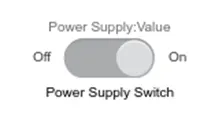
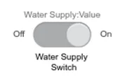
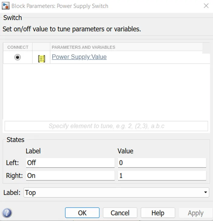
Power Supply Switch is Connect to the constant value; Left is the OFF Condition is “0” And the Right is the ON Condition is “1”.
Simulink Block Diagram:
Implement control logic of a “washing machine” using State flow:
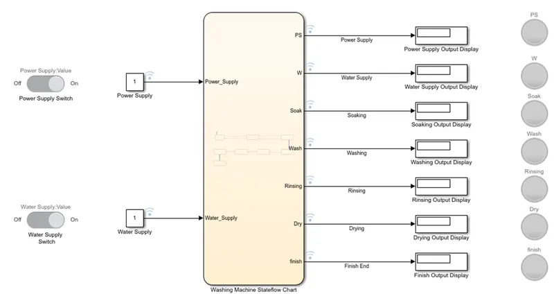
This Simulink block diagram Represents the Washing machine Control using the state flow this will have the logic inside the chart is executed according to the given conditions,
The power supply switch and the water supply switch is turned on that is ‘1’ so the condition is true, inside the chart the program is ready to execute according to the conditions we have designed the output value is shown in the display and its connected to the lamp for the indicating the output under the several functions.
Chart Diagram:
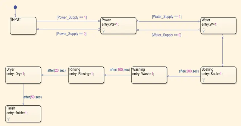
In the Above control Logic, we have created the given conditions using Stateflow:
- The Input is given the Power_Supply==1 if the condition true (PS=1)
- Its again check whether the Water Supply is ON ‘Water_Supply==1, when both the conditions are true, its just move on to the next level,
- Soaking is done for the 200 Seconds, after completed,
- Washing is performed for 100 Seconds.
- Rinsing is done for 20 seconds.
- Finally, Dryer is active and go on for 50 Seconds.
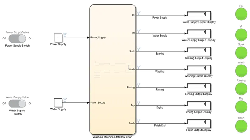
- At last all the operations completed to move on to finish. The washing machine is off state with the indicating lamps Green.
Note: While finishing each steps the lamp is connected to each output block of the operation to easily identification.
SYMBOLS PANE:
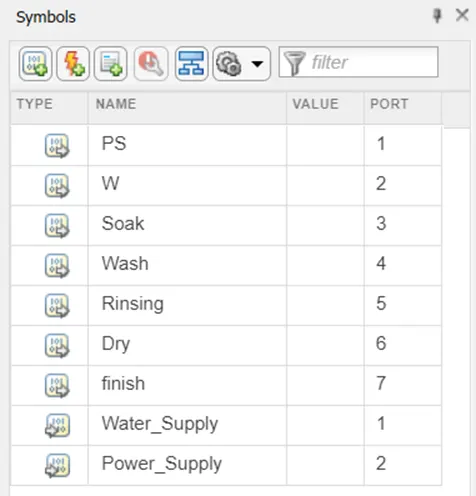
Symbols Pane displays the name of the blocks we had created and the port numbers.
We can make also changes in the block here.
Run Time:
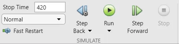
Here the maximum run time is set to 420 is enough to display the final output.
The Step forward is used to simulate the output step by step and its is easy to check the conditions.
OUTPUT:
The two conditions are asked in the question:
Condition 1:
If the power supply is available, the system gets activated
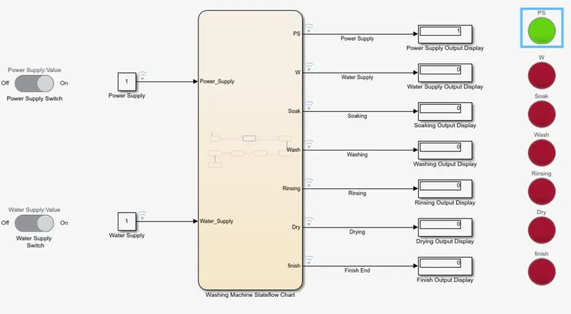
When the power Supply is available the display value shows ‘1’ and the Lamp ‘Green’ light is turned on for the indication. Next its wait for the water supply input.
Condition 2:
If the Water supply is not available, stop the process & indicate through LED.
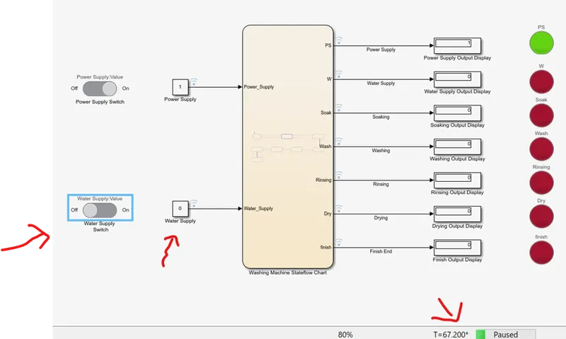
If the water supply is turned off, or not available the machine won’t run its stopped when the time value is also increasing is shown, and the process is stopped and indicated through the red lamp, and the display as ‘0’.
When the water supply is turned ON:
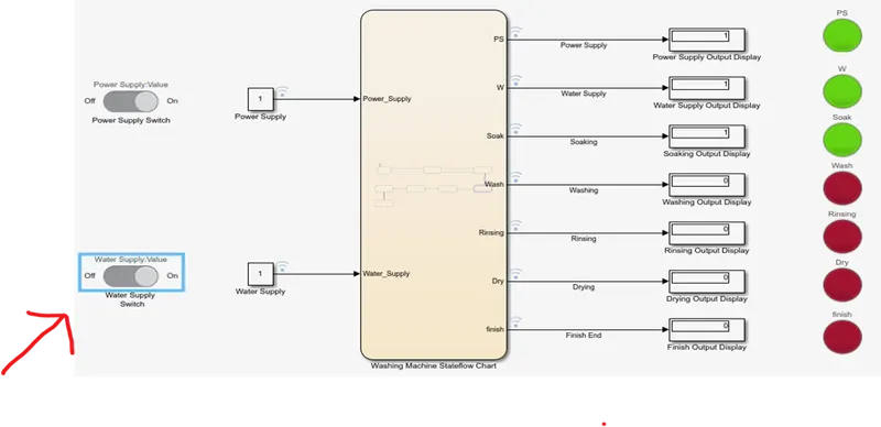
The water supply turned ON the conditions are executed ,and
- The Soaking is for 200 Seconds.
- Washing time of 100 Seconds.
- Rinsing for 20 Seconds.
- Dryer for 50 Seconds.
Finish Lamp will be turned to green. The final output image is attached below;
Conclusion:
Thus, for the given conditions the Simulation of the Washing Machine using state flow is successfully created.
Task 2:
- Make a Simulink chart for the “Gear shift” logic as per below conditions:
Speed Range (kmph) Gear
0 to 15 1
16 to 25 2
26 to 40 3
41 to 60 4
Above 61 5
Give speed input while the simulation is running & display the gear number.
Answer:
Blocks Used:
Slider:
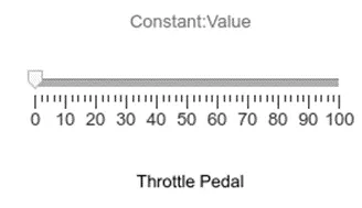
Here the Slider to vary the Speed, in real time we have to say as throttle for the vehicle.
Constant:
Use this block to provide a constant signal input. Constant block generates a real or complex constant value signal. Its id connected to the slider to vary the speed.
Simulink Chart diagram for the ‘Gear Shift’:
Display:
This play role in the display the input Signal we have given, for numeric input data, you can also specify the format of the display.
Lamp:
Display a color that reflects an input value. The lamp is connected to the chart diagram to display the output in the indicative colors as we chosen, this is used to monitoring the output while running the simulation.

Block Diagram for the Model:
GEAR SHIFT:
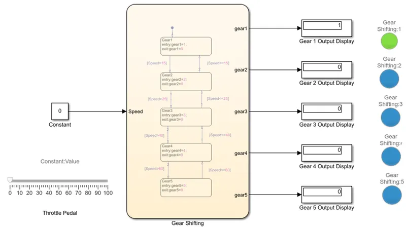
The constant block is used to provide the continues input to the slider gain block,
Here the slider gain we set to the maximum value 150 that we can vary during simulation, the slider gain input value is provided to the chart or the state flow block where the block contains the several working conditions it will execute according the to the input given by the slider gain.
The output value is showed in the lamp with the indicative colors and from the display.
CHART DIAGRAM:
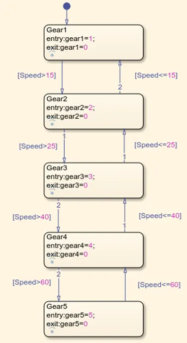
In the above control logic,
The Moving condition for the Gear Shifting is;
- Initially Gear 1 , If speed>15 it will shift to Gear 2.
- When Speed>25 it goes to gear 3.
- When Speed>40 it moves on to gear 4.
- When Speed>60 is goes to gear 5. And the maximum speed 100.
Similarly, in the reverse direction;
- Speed<=60 shift to Gear 4.
- Speed<=40 it shifts to Gear 3.
- Speed<=25 it shifts to Gear 2.
- Speed<=15 is shift to Gear 1. When the speed reduces.
Symbol Pane:
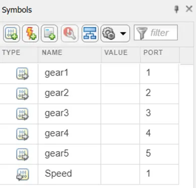
This indicates the name and the port we are connected, we can change the input and the output here.
Different Speed input while the Simulation is running:
Simulink Model at different Speed:
When the Speed=10 it is in the Gear 1., the Output display is 1 and the lamp will indicate in green Light.
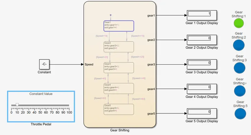
When the Speed=20 it is in the Gear 2 that is Speed>15., the Output display is 2 and the lamp will indicate in green Light.
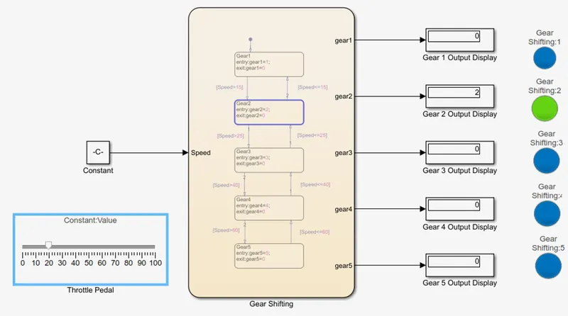
When the Speed=30 it is in the Gear 3 that is Speed>25., the Output display is 3 and the lamp will indicate in green Light.
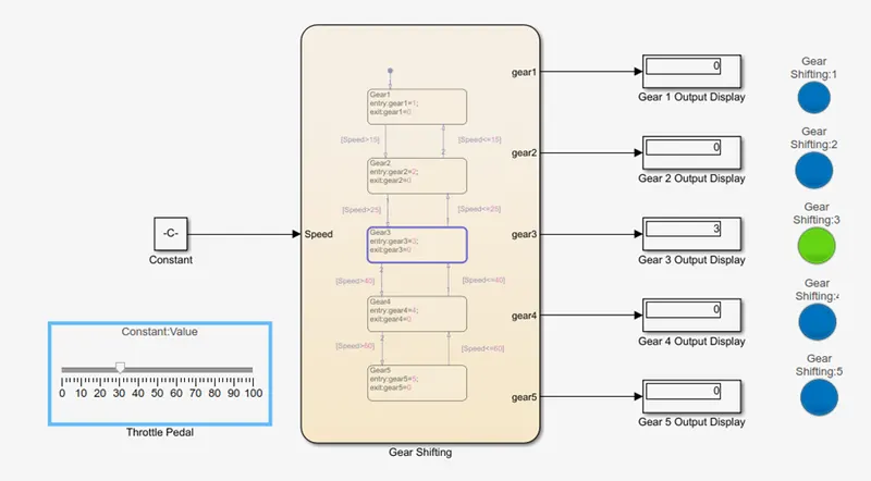
When the Speed=50 it is in the Gear 4 that is Speed>40., the Output display is 4 and the lamp will indicate in green Light.
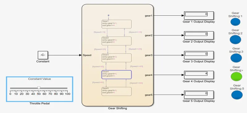
When the Speed=70 it is in the Gear 5 that is Speed>60., the Output display is 5 and the lamp will indicate in green Light.
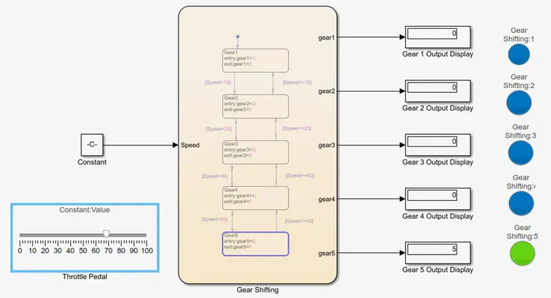
Note: This Works as well as in the Reverse conditions.
Conclusion:
Thus, for the given Gear Shift condition the Simulink Block Diagram is created successfully and for the different speed variations the gear transmission is noted and attached.