Project 2
Project 2
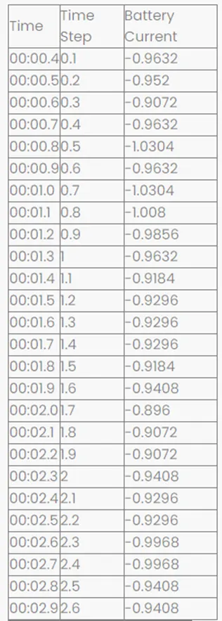
- Using MATLAB/Simulink and the drive cycle from the attached excel sheet, find-
- The max heat generation of the battery
- The SOC of the battery at 2 *104second of the battery operation

Answer:
- The battery's maximum heat production
For the battery heat generation, there are two heat sources.
Joules heat
Entropy heat
Heat generated = Joules Heat + Entropy Heat
P = V*I
= I*I*R
= I2*R
The heat produced by the radiator is:
according to the square of the current that is passing through it
proportionally to the resistance
in direct proportion to the duration of the current's passage through it.
Entropy Heat:
When electrochemical reactions take place inside a battery, heat is produced due to the change in entropy. The change in open circuit voltage with respect to temperature at two electrodes causes reversible heat known as entropy.
Given Specifications
Battery resistance = 0.5 mOhm
Maximum Current = -0.896 A
Max current time = 2 min
Entropic factor = 2
Total heat generation = Joule heat + Entropy heat
The maximum heat generation in the battery pack:
Max heat generation = Max Joule Heat + Entropy Heat
Max Joule Heat = I2*R*t
Max Joule Heat = (−0.8962)2 * 0.5 * 120
Max Joule Heat = 48.19047
Max heat generation = 48.19047+ 2 = 50.19047Joules
The Maximum heat generation is 50.19047 millijoules
- The SOC of the battery at 2 *104second of the battery operation
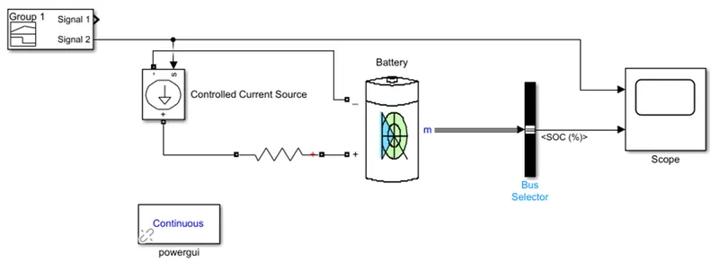
Blocks Used:
1) Signal Builder
2) Controlled Current Source
3) Resistor
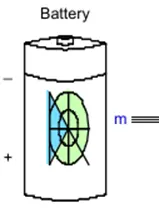
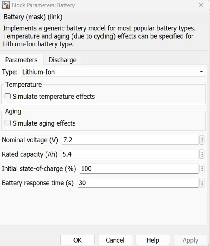
4)Battery
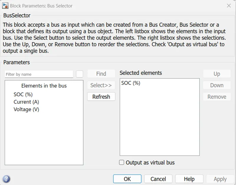
5)Bus Selector
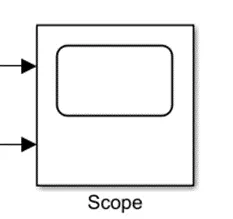
6)Scope
7)Powergui
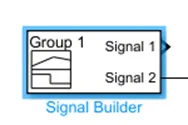
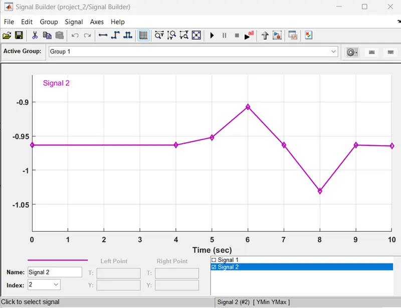
1) Signal Builder:
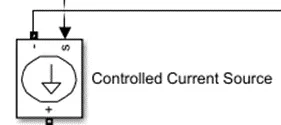
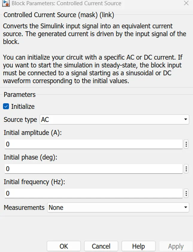
2) Controlled Current Source:
3) Resistor:
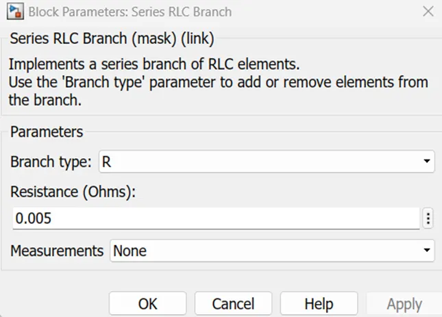
4)Battery:
5)Bus Selector:

6)Scope:
7)Powergui:
Drive Cycle Input:
- Through the drive cycle input block, which is an excel file provided in the query, this current cycle is provided as the input to the model.
- The simulation runs for 208 seconds since the drive cycle stop time in this case is 2*104, or 208 seconds.
- The battery is discharged here in accordance with the signal provided by the data, which is Excel data input drive cycle data, since the output of the drive cycle is being sent to the current-controlled source, which is connected to the battery as a load.
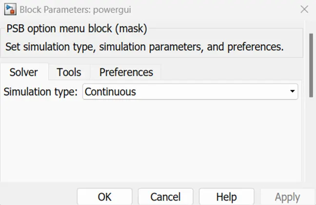
- For any simulation of the Simulink model, the powergui block is required here.
- The analogous Simulink circuit, which symbolizes the State Space Model, is mostly used to store data.
- Through the bus selector, a battery's output is delivered to the scope. The scope receives the battery signals from the bus selector.
OUTPUT RESULT(SCOPE):
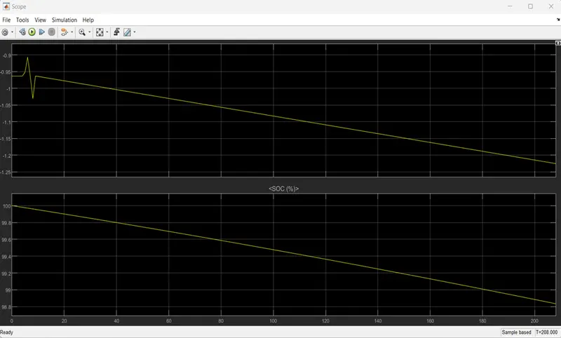
The SOC voltage and current results are shown in the graph above.
Here, we ran the battery's soc at 2*104
Additionally, we can observe that the battery's SOC primarily declines from 100 to 98.9, and the voltage likewise decreases.
Conclusion:
Thus, for the above questions the report has created successfully.