Project 1
Project 1
Design a battery pack for a car roughly 150 Kw with 120 V. Use 3500 m Ah 3.6V nominal NMC chemistry cell.
- Design the battery pack configuration.
- Draw the BMS topology for this battery Pack
Answer:
Aim:
Utilizing 3500mAh at 3.6V, a battery pack with a 150Kw 120V capacity was designed. Additionally, the battery pack's BMS topology
Calculation: (To design the battery pack Configuration)
In order to create a battery pack that meets the requirements, cells must be connected in both series and parallel.
The given cells values are:
Nominal Cell Current = 3500 m Ah that is 3.5 V
Nominal Voltage (Cell) = 3.6 V
We must determine the number of cells connected in series and parallel to achieve the required 120 volts and 150 kW.
First, convert 150 Kw of battery capacity to Ah.
Amp Hour = Watt hour / Voltage
Amp Hour = 150 * 103 /120
= 150*1000 / 120
Battery Current = 1250 Ah
Series Calculation:
Number of cells in series = Battery Voltage / Nominal cell voltage
Number of cells in series = 120 / 3.6
Number of cells in series = 33.33
We have to round off to lower value and higher value = 34 Cells in Series
Therefore, Number of cells in series = 34.
Parallel Calculation:
Number of cells in Parallel = Battery Current / Nominal cell Current
Number of cells in Parallel = 1250 / 3.5
Number of cells in Parallel = 357.14
We have to round off to lower value and higher value = 358 Cells in Parallel
Therefore, Number of cells in series = 358.
Total No of Cells in Series & Parallel = Series * Parallel
Total No of Cells = 12,172 (Cells in Series & Parallel)
- Draw the BMS topology for this battery pack.
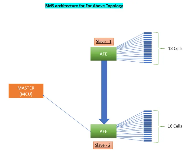
Here we use Master and Slave Topology:
As a result, the slave unit keeps track of, regulates, and manages a collection of battery cells inside the battery module.
Through a communication interface, it communicates with the master unit.
Power Distribution Unit PDU state estimates control and external communication are handled by the Master unit.
The master-slave BMS is comparable to a modular system in that it makes use of numerous identical modules, with the slaves each sensing a small number of cells' voltage.
The master, on the other hand, differs from the modules in that it doesn't measure voltages.
Only computation and communication are handled.
Manufacturing is challenging due to the large number of parallel and series cells. In order to achieve the desired output, we must separate it into smaller battery packs and reconstruct the connections.
We must divide the 34 series cells into an 18 cells series sub battery pack because the BMS can only support a maximum of 18 series cells. This results in two series sub connections, one with 18 cells and the other with 16 cells.
Because this design consists of Master and Slave BMS units, we primarily used the Master Salve topology in this case.
Battery Management System (BMS):
This battery pack's BMS Topology is a Master and Slave BMS Topology. It will be simple to regulate and manufacture because the whole battery pack is composed of smaller battery packs.
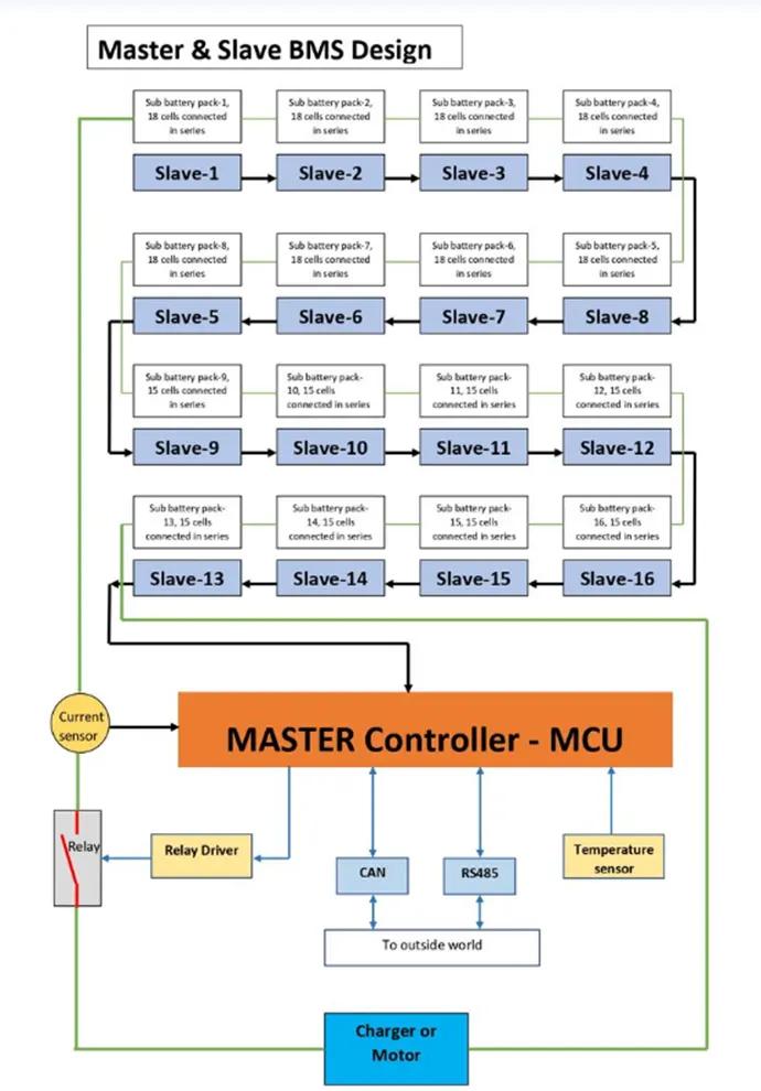
It has input temperature, current, and voltage sensors. The analogue signal from the voltage sensor is converted to a digital signal by the AFE; the analogue signal from the current sensor is converted to a digital signal by the MCU; alternatively, the current sensor and MCU may be connected via an ADC converter; and the analogue signal from the temperature sensor is converted to a digital signal by the MCU; alternatively, the temperature sensor may be connected via an ADC converter. By receiving a command from the MCU, the Really module controls the Really that creates or breaks the circuit. Communication prototypes to the outside world include CAN and RS485.
The BMS blocks are the ones inside the red line. The three 18 cell Slave controllers, which is AFE-designed, translates the analogue signal from the battery's voltage sensor to a digital signal.
The three slaves are connected in series as shown, with slave-1 collecting data from module 1 and sending it to slave-2, slave-2 collecting data from module 2, slave-3 collecting data from module 3, slave-3 collecting data from module 1, slaves-1, 2, and 3, and so forth until all 16 slaves have completed their work, at which point all data is sent to the master controller, which is the MCU. According to the protocols that are sent to the MCU, it controls the battery pack.
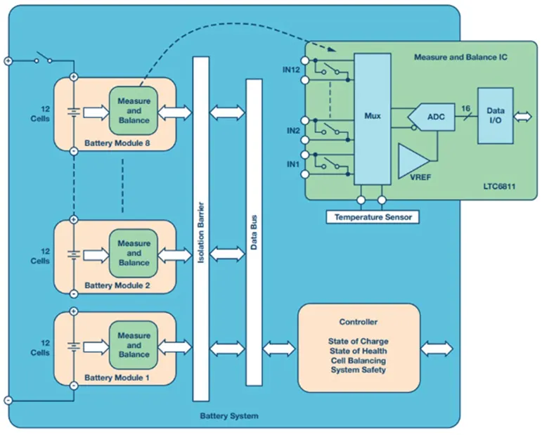
Even though half of the sub battery packs only have 15 series cells, all the slaves have a capacity of 18 cells in series. This is because if we wish to increase the capacity, we can do so by raising the Ah of the battery pack, or by increasing the number of series cells. Although in a limited way, it makes upgrading the battery pack simple.
Conclusion:
Both the battery pack configuration and the BMS architecture have been successfully designed.