Project-1: Powertrain for aircraft in runways
Project-1
Powertrain for Aircraft in Runways
Part A:
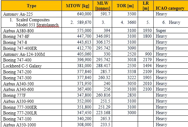
- Search and list out the total weight of various types of aircrafts.
- Is there any difference between ground speed and air speed?
- Why is it not recommended to use aircraft engine power to move it on the ground at Airport?
- How an aircraft is pushed to runway when its ready to take off?
- Learn about takeoff power, tyre design, rolling resistance, tyre pressure, brake forces when landing.
Part B:
- A. With necessary assumptions, calculate the force and power required to push / pull an aircraft by a towing vehicle.
- Develop the model for the calculated force and power using Simulink.
- A. Design an electric powertrain with type of motor, it’s power rating, and energy requirement to fulfill aircraft towing application in Simulink. Estimate the duty cycle range to control the aircraft speed from zero to highest. Make all required assumptions. Prepare a table of assumed parameters. Draw a block diagram of powertrain.
(Hint :DC7 Block)
- Also, Design the parameters in excel sheet.
Answer:
Part-A
- Search and list out the total weight of various types of aircrafts.
We may estimate weight using the following formula because, as we know, weight is the force created by the earth's gravitational pull. The formula for weight is w=m*g, where w represents the weight, m the mass, and g the gravitational constants. g equals 9.8 m/s2 or 32.2 ft/s2. As an example, the wings, engines, cargo, and fuel are only a few of the several sections of an aero plane, each of which carries a distinct weight and mass. If we are aware of the size and chemical makeup of each component, such as iron, plastic, aluminum, gasoline, etc., we may determine the mass of each component separately.
In other words, W=w(Fuselage)+w(Payload)+w(Engines)+w(Wings)+ is the sum of the weights of the aircraft's individual parts.
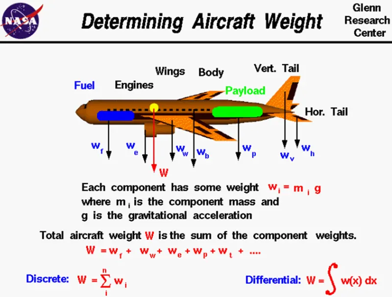
An aircraft's center of gravity (CG) is determined as follows:
- Find out the weights and arms of every piece of mass inside the aero plane.
- To calculate moments, multiply weights by arms for all mass.
- the sum of all mass's moments.
- To determine the overall arm of the aircraft, divide the entire moment by the total mass of the plane.
This computation must yield an arm that falls within the aircraft manufacturer's permitted center of gravity ranges. If not, weight must be changed in the aircraft—either by adding weight (rarely), subtracting weight, or redistributing weight—until the center of gravity is within the allowed range.
From the zero point of the reference datum, which corresponds to the aircraft's longitudinal axis, calculations of the center of gravity for aircraft are only made along one axis (to calculate fore-to-aft balance). Some models of helicopters employ both longitudinal and lateral CG limitations. In order to operate these helicopters, CG must be calculated along two axes: longitudinal CG (fore-to-aft balance) and lateral CG (left-to-right balance)
The manufacturer provides the weight, moment, and arm values on the Aircraft Equipment List for fixed equipment on the aircraft, such as the engines, wings, and electrical components, which do not change. The manufacturer also offers details that make it easier to calculate fuel load moments. The aero plane operator must accurately account for removable weight items (such as baggage, passengers, and crew members) while calculating the aircraft's weight and center of gravity (CG).
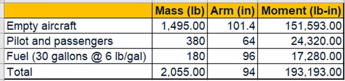
To find the center of gravity = Total moment / Total mass
= 193193/2055
= 94 Inches
The overall weight of the aircraft at any point during the flight or land operation is known as the aircraft authorized gross weight. The AFM and the weight and balance handbook contain a list of the authorized weight restrictions that may be employed legally by any operator or airline. Additionally, they are known as purchased weights.
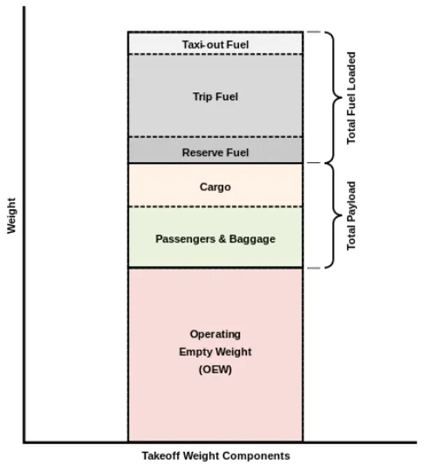
The following categories can be used to group various forms of weight under gross weight:
Maximum ramp weight (MRW):
According to standards for the strength or airworthiness of the aircraft, it is described as the maximum weight permitted for towing or taxiing on the ground. The difference between the maximum takeoff weight and the maximum ramp weight is influenced by the size of the aircraft, the number of engines, the use of the APU, and the fuel consumption of the engines. This is usually based on assumptions for 10 to 15 minutes of taxiing, towing, and run-up activities.
Maximum take-off weight (MTOW):
According to aircraft strength and airworthiness requirements, it is defined as the maximum certified design weight for takeoff runs. The maximum take-off weight is consistently lower than the maximum ramp weight to compensate for gasoline burned by the engines and the APU during taxi.
Maximum landing weight (MLW):
The maximum design certified weight allowed for an aircraft's normal landing is how it is defined. The strength of the landing gear or the impact loads of the landing on particular components of the wing and chassis construction are the key determining factors.
MDLW<MDTOW<MRW
Maximum zero fuel weight (MZFW):
The maximum certified weight of an aero plane without usable fuel is known as its maximum zero fuel weight. Other weights are constrained by the aircraft's strength and airworthiness criteria. In other words, it is the weight that can be loaded into the aero plane before useful liquid and other materials are added.
Operational empty weight (OEW):
The only times the OEW is modified is when an aircraft undergoes maintenance or operational adjustments. When using a flight simulator or standard planning software, empty weight, or OEW, is employed.
Actual zero fuel weight (AZFW):
The true zero fuel weight is obtained by adding the cargo to the empty plane weight. Basically, the payload consists of the weights of the cargo and passenger bags as indicated by the following relations.
Minimum Flight weight (MFW):
According to restrictions on aircraft strength and airworthiness, the minimum certified weight for flying. Empty weight with payload is included in an aircraft's overall weight.
Aircraft’s empty weight:
The weight of the aero plane with fuel still in the tank, engine oil, and other operating fluids
Payload:
The weight of the working fluids plus the weight of the passengers and fuel.
To find Actual zero fuel weight:
Actual zero fuel weight = Operational empty weight + Payload.
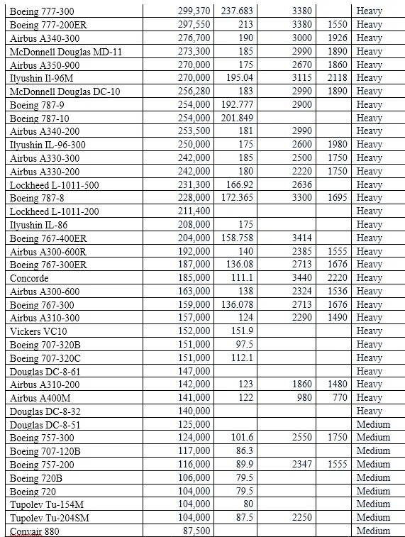
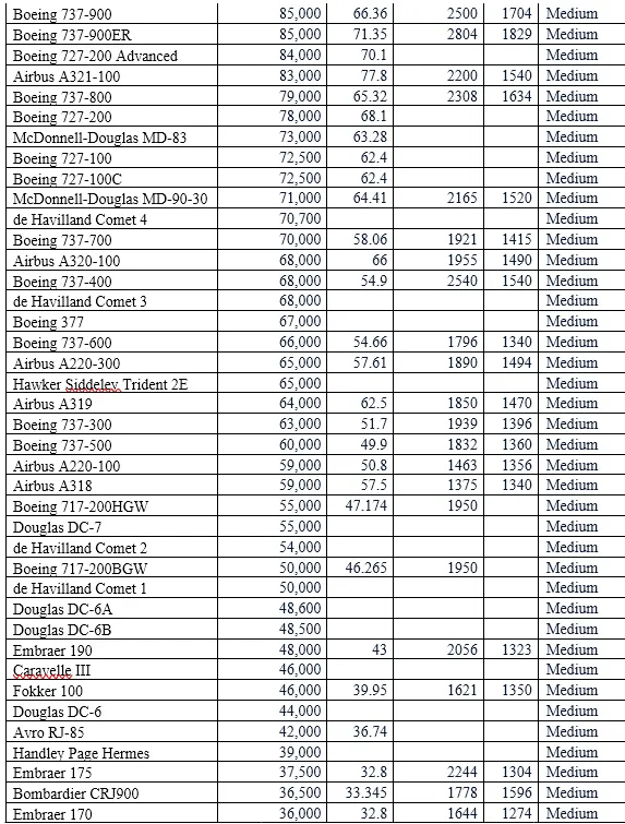
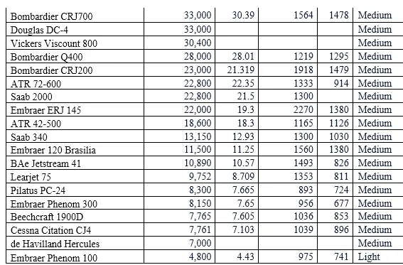
- Is there any difference between ground speed and air speed?
To determine if you can safely complete a flight, it is crucial to distinguish between and fully comprehend the phrases because they will be crucial to your distance and fuel estimates. Airspeed is important to the pilots because it determines how the plane feels as it flies. On the other side, ground speed is how rapidly you are getting when you are moving, which is also crucial because the engine burns a set amount of fuel per hour. Too little ground speed and the wings won't be able to generate enough lift to fly, and too much can be able to harm the plane.
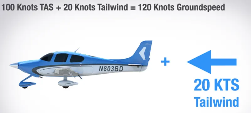
Accordingly, if an airplane's ground speed is 100 knots, its relative airspeed is 100 nm per hour. This speed is affected by the headwind and the tailwind; if the aircraft received a tailwind, the ground speed would be higher than the air speed, and vice versa.
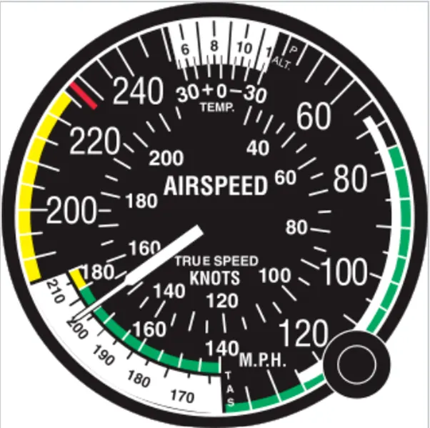
Indicated Airspeed (IAS):
This is the airplane's airspeed, calculated using the static air pressure in the area where it is flying and the ratio between stagnation and it. The mentioned air speed values are all written as the speed limits of the sky, such as not going above 250 knots below 10,000 feet MSL.
Calibrated Airspeed (CAS):
Installation and equipment errors have been fixed in this airspeed indication. Based on the installation, it shows a more accurate airspeed at STP. The installation and instrument mistakes may total a few knots at a certain air speed with a particular flap setting, and they may be even greater at low airspeeds with high pitch attitudes in the nose. When there is no wind, calibrated air speed is identical to true air speed. It is also equivalent to ground speed.
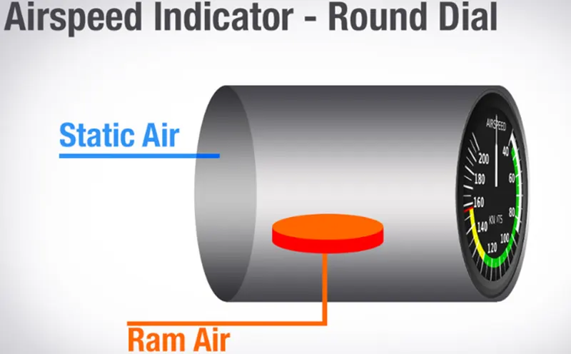
True Airspeed (TAS):
For non-standard pressure and temperature, it is the indicated airspeed adjusted. The relative airflow over the aircraft is depicted at its real speed. The ground speed and TAS are equivalent in still air. As you climb, less and fewer air molecules will enter the pilot tube, resulting in an indicated air speed that is always less than the true air speed for any given true air speed since pressure falls with altitude.
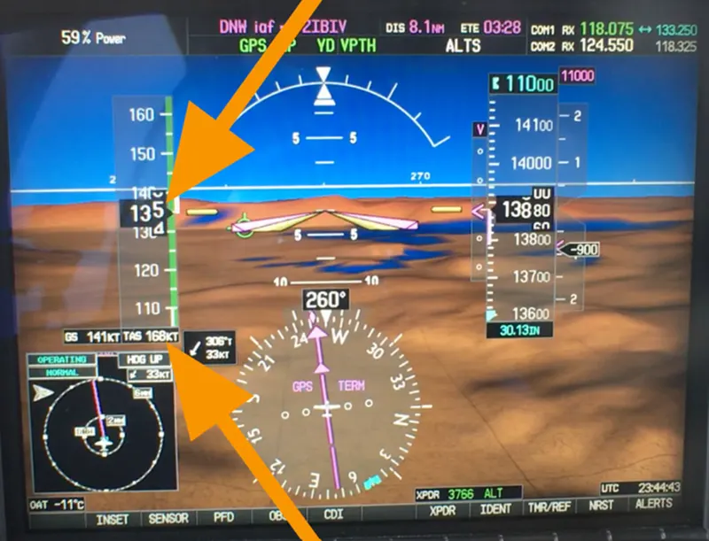
Ground Speed (GS):
It refers to how quickly an aero plane is flying over the earth. The genuine air speed of the aircraft plus the headwind portion of the wind aloft at the altitude the aircraft is flying at will equal the total.
Wind Speed:
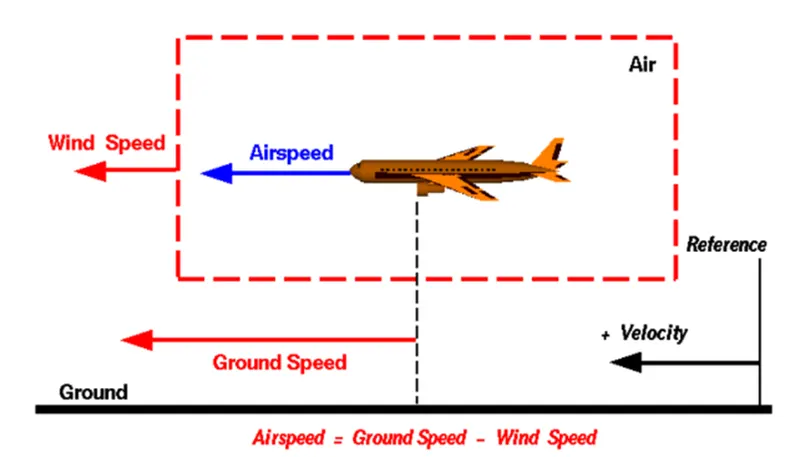
The air moves relative to a reference point chosen on the ground at the rate of the wind. Keep in mind that the wind speed has a magnitude and a direction, making it a vector quantity. Navigation is crucial. A 20-mph wind from the west differs from an easterly 20 mph wind. The wind has elements in each of the three major directions (north-south, east-west, and up-down). In this graph, just the speeds along the plane's flight route are considered. A positive velocity is one that is in the plane's direction of motion. We are ignoring cross winds, which are parallel to the ground but occur perpendicular to the flight path, as well as updrafts and downdrafts, which are perpendicular to the ground.
Airspeed:
The airspeed, or relative velocity between the object and the air, is a crucial factor in the production of lift. From a ground position, airspeed cannot be determined directly; instead, it must be calculated from the ground speed and the wind speed. The vector difference between ground speed and wind speed is known as airspeed.
Airspeed = Ground Speed - Wind Speed
The airspeed and ground speed are equivalent on a completely motionless day. The airspeed, however, will be slower than the ground speed if the wind is blowing in the same direction that the aircraft is travelling.
EXAMPLE:
Imagine if we had a plane that could fly at 100 mph on a windless day (liftoff airspeed is 100 mph). We are at an airfield with a 1-mile-long east-west runway. The aircraft takes off travelling east against a 20 mph breeze out of the west. A headwind is when the wind is blowing in the direction of the aircraft. A headwind is a negative velocity since the direction of the aircraft's motion is how we define a positive velocity. The aircraft is stationary on the runway, with a ground speed of zero and an airspeed of twenty miles per hour:
Airspeed = Ground Speed (0) - Wind Speed (-20) = 20 mph
The aircraft begins its takeoff roll while accelerating steadily. The ground speed V at any moment t is determined by Newton's second law of motion and is:
V = a * t
Where the runway's length d at any given time is:
d = 1/2 * a * t^2
This defines the time to be used in the velocity equation for a runway with a set length. Assume the velocity is 80 mph at 5000 feet down the runway. The airspeed is then provided by
100 mph is equal to ground speed (80 mph) minus wind speed (20 mph).
and the aircraft takes off. Now another pilot decides to take off to the west in the exact same aircraft. A tailwind is created when the wind now blows in the same direction as the motion. In contrast to a headwind, the wind speed now has a positive indication. At 5000 feet down the runway, the ground speed is once more 80 mph because the acceleration along the ground is the same. The following provides the airspeed:
Airspeed = Ground Speed (80) - Wind Speed (20) = 60 mph
This aircraft lacks the necessary airspeed to take flight. It exits the runway at the end.
Wind tunnel testing is made possible by the link between airspeed, wind speed, and ground speed, which also explains how kites fly.
- Since the model is fixed to the tunnel walls in the wind tunnel, the ground speed is zero. The airspeed is then equal to the wind speed produced in the tunnel multiplied by itself. The forces are the same whether the thing is moving through the air or the air is moving over it.
- Due to the fact that it is held on a string, a kite often has no ground speed. The kite's airspeed, however, remains the same as the winds. Only with the wind at your back can you fly a kite.
- Why is it not recommended to use aircraft engine power to move it on the ground at Airport?
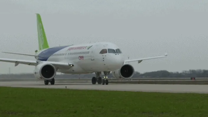
The aircraft's engine can easily accomplish the task of moving near runaways and, after landing, taxiing to their designated gate. However, since the engine is so strong, the jet blast created by the thrust could harm the terminal building or other persons and/or equipment. Sand and other debris may be blown back and forth by engines that are near to the ground, where they may be drawn into the engine. Therefore, a pushback is the most effective approach to get the aircraft out of the gate while still saving money on fuel. A lot of money can be saved through taxing.
- Ground support personnel who may be near to the aircraft run the danger of being hurt.
- Compared to the pilot, who is seated in the cockpit with a small glass, it is simpler for the truck driver to view the surroundings more clearly. The pushback driver is more familiar with the airport than the pilot is.
- Effectively, it is possible to lose control, especially when driving a high-power engine. The aero plane itself, surrounding aircraft, and other buildings could sustain damage.
- To save fuel and lessen the impact on the environment, a novel system was developed in which a push-back truck would bring the aircraft all the way to the runway.
- It will be intolerable for passengers and other areas surrounding the airport when the sound of multiple planes' engines is added together.
- How an aircraft is pushed to runway when its ready to take off?
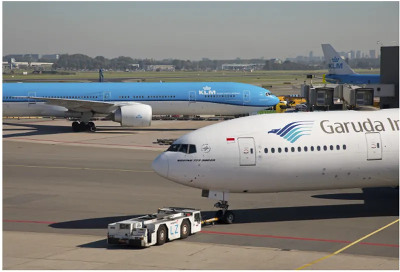
TAXIING:
In contrast to towing or pushback, which involves the tug moving the aircraft, it is described as the movement of the aircraft on the ground while operating independently. However, the phrase is also used to describe aircraft with skies or equipment that floats. Aircraft are typically propelled by wheels. When moving from one location on the airport to another, such as from a hangar to a runway, an aero plane uses taxiways.
TOWING:
Towing with a tow tractor, often known as a "tug," is typically used to move heavy aircraft about the airport, flight line, and hangar. When moving small aircraft, some of the work is done by hand pushing on the appropriate areas of the craft. Taxying an aircraft around the flight line is also possible, but typically only by specific skilled individuals.
If done hastily or irresponsibly, towing an aero plane can be a dangerous activity that damages the aircraft and injures workers. The manufacturer's maintenance instructions, however, contain detailed instructions for each model of aircraft and must always be followed. The towing vehicle must move at a suitable speed while towing the aero plane, and everyone involved in the operation must be alert. Do not rely solely on the brakes of the towing vehicle to bring the aero plane to a stop. The person on the flight deck is responsible for coordinating the use of the brakes on the aircraft and the towing vehicle.
- Learn about takeoff power, tyre design, rolling resistance, tyre pressure, brake forces when landing.
Take off power:
Consider the case where the car takes off and flies through the air.
The aero plane initially runs on the runway for a typical amount of time to attain its top speed and take off.
The more power needed to lift off, but the performance of the engine should be considered for better operation and longevity.
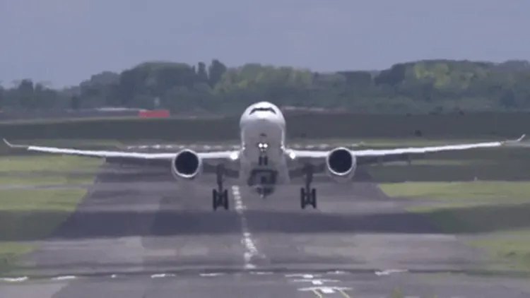
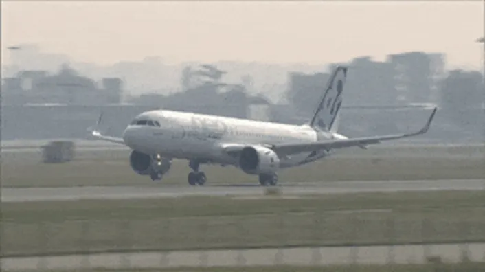
On takeoff, the aircraft attitude is pitched up to maintain a specific speed (typically in the vicinity of V2 + 15 kts) and the engine thrust is set to a high "take-off power" setting (although this is not necessarily full power). This is done to position the aircraft to a safe height away from terrain and obstacles.
The aircraft flight route can also be modified to one that is more appropriate (i.e. efficient) once the ‘safe height' has been achieved.
Regulatory rules require aircraft to fly one of the two profiles listed below during every departure in order to accomplish the goals outlined above and to minimize noise annoyance to the region surrounding the airport.
Tyre design:
Tyres are one of the most crucial parts of an aero plane in terms of safety. They serve as a cushion and aid in absorbing the impact of landing. Additionally, it gives an aero plane the traction it needs to brake and halt. A plane's tyres are made to resist incredibly heavy weights during takeoff, landing, taxing, and parking. Given that the weight of the aircraft must be spread more equally, the number of wheels needed for an aircraft rises as its weight does.
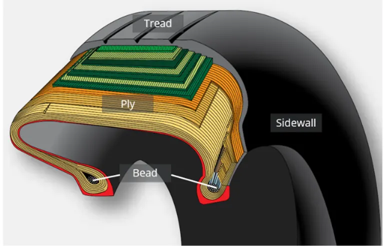
- When an aero plane is on the ground, they bear its weight.
- Additionally, it gives an aero plane the traction it needs to halt and brake.
- The stress of landing and the roughness of takeoff, roll-out, and taxi operations are also cushioned by the tyre.
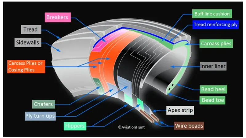
The tyre is made using carcass plies. They are also known as casing plies. An aviation tyre is made specifically for the use it will have.
When retracted via landing gear, aircraft tyres must have enough room to accommodate tyre growth and have a speed and load rating that has been certified. Tyre growth is an increase in tyre size brought on by high-speed centrifugal forces.
Some of the technical features of an aircraft tyre include:
Tube or tube less:
Tyres without tubes have an advantage over those with tubes. In more contemporary aviation, tube-type tyres are no longer used. All modern aero planes have tubeless tyres. The word TUBELESS is printed on the sidewall of tyres that are intended to be operated without tubes.
Speed Rating:
The highest takeoff speed to which the tyre has been tested is the speed rating.
Retreading:
Retreading is a technique for regenerating a worn-out tire's tread or tread region as well as one or both sidewalls. The process of tyre retreading includes repairs.
Load Rating:
The maximum allowable load at a given inflation pressure is known as the load rating.
Skid Depth:
Skid depth, as measured in the mold, is the separation between the tread surface and the deepest groove.
Ply Rating:
For a specific tyre, the maximum recommended load rating and inflation pressure are determined by the ply rating. It measures the strength of tyres.
Rolling resistance:
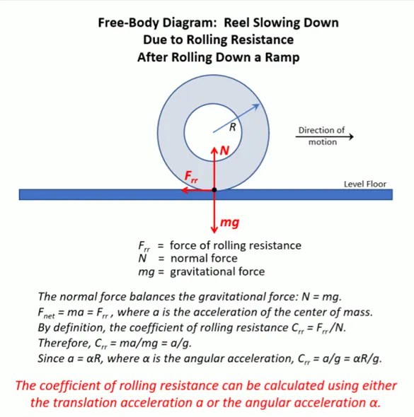
As we are aware, the tyre received a force. The force applied to the aero plane tyre is this. It relies on the tire's structure, material, temperature around it, and tyre pressure. We believe that... provides the force necessary to overcome the rolling resistance.
The force that opposes the motion when a body (such as a ball, tyre, or wheel) rolls on a surface is known as the rolling resistance.
When an aero plane takes off from the runway with the aid of the runway and when it lands, the rolling resistance of its wheels can be observed.
Frr=μrr*mg
where,
μrr = Rolling resistance coefficient
m = mass of the tyre,
g= The gravitational constant
TYRE PRESSURE:
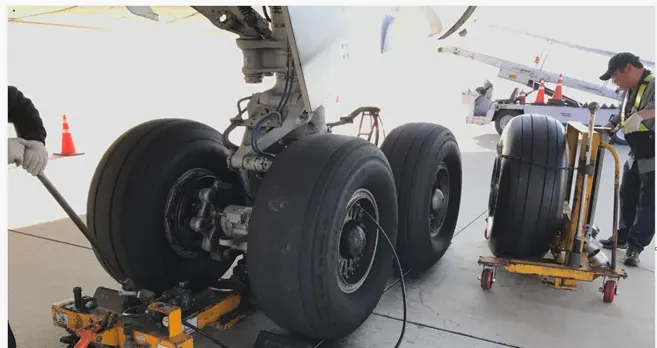
- Airliner tyres can operate at pressures of up to 200 psi (14 bar; 1.400 kPa), while business jet tyres can work at levels considerably higher.
- The Concorde's tail bumper gear tyres could be inflated to 294 psi, while its main landing gear was generally inflated to 232 psi (16.0 bar) (20.3 bar).
- Airliner aircraft tyres can withstand pressures of up to 800 psi (55 bar, 5.500 kPa) before exploding, according to tests. To prevent the test room from being destroyed by the energy that would be produced by a gas when a tyre explodes, the tyres must be filled with water while being tested. Nitrogen is typically used to inflate aircraft tyres to reduce
- Extreme fluctuations in the outside temperature and pressure that are encountered while flying cause expansion and contraction. dried nitrogen Although typical air contains around 80% nitrogen, layer expands at the same rate as other dry atmospheric gases. However, moisture content in common compressed air sources can change with temperature. which promotes expansion
- The requirement that an inert gas, such as nitrogen, be used instead of air to inflate tyres on specific transport category aero planes was brought about by at least three instances in which the oxygen in air-filled tyres combined with volatile gases released by a severely overheated tyre and exploded upon reaching auto-ignition temperature. By using inert gas to fill tyres, the risk of a tyre explosion is completely eliminated.
Brake forces when landing:
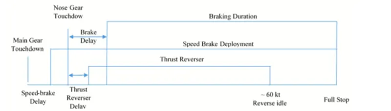
It is exceedingly risky to attempt to stop the aero plane from landing at a speed of more than 150 mph. Braking systems are essential to an aircraft's ability to safely land on runways. For instance, an Airbus 320 with a weight of about 75 tones may land at 150 to 160 mph. The aero plane must cautiously use its brakes after contacting the ground to come to a stop.
The following techniques are used to brake an aircraft:
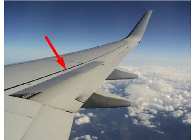
Wing spoilers:
The majority of aircraft use their wing spoilers to aid with landing slowing. The wings' end folds that can be extended are known as spoilers. After reaching the runway, the pilots lift the spoilers and maintain them there until the jet comes to a complete stop. The higher spoiler causes more drag, which slows the aircraft.
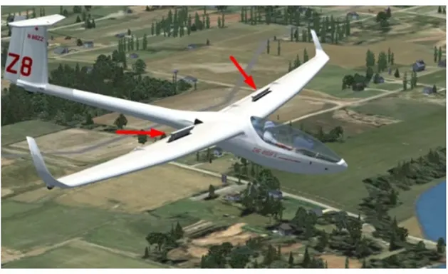
Spoilers are most frequently employed on gliders to regulate the pace of descent for precise landings. Glider pilots can increase drag, drop the nose, and accelerate descent by extending spoilers without appreciably increasing airspeed. Like certain other light aircraft, such as the Mooney M20, gliders frequently have vertical-type spoilers that, when raised, obstruct airflow over the aft portion of the wing.
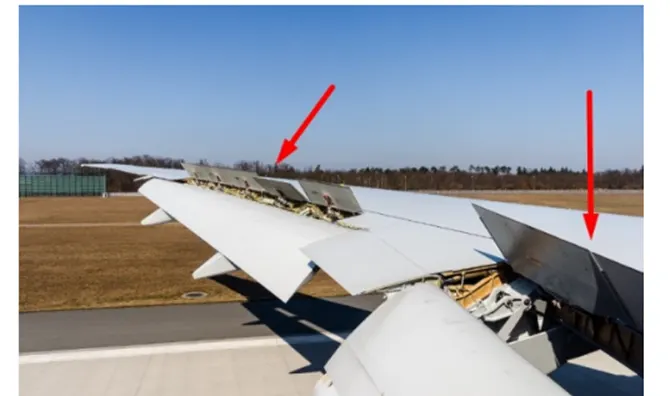
ROLL CONTROL:
Roll control frequently makes use of spoilers. They are sometimes referred to as spoilers. To help the ailerons on each wing bank the aero plane, they are deployed asymmetrically. The decrease in unfavorable events in a bank is the other benefit. For instance, when turning to the right, the right wing's spoiler is lifted, reducing some of the lift and increasing drag. The aero plane yaws to the right and lowers its right wing. This makes it easier to maintain coordination since it keeps your nose in line with the turn.
REDUCING GROUND ROLL:
Additionally, spoilers are used to lessen ground roll following landing. Because your wings are still producing lift as you land, your landing gear is not very heavily loaded, which reduces the effectiveness of your braking. When an aero plane lands, it detects when its wheels hit the ground and deploys its ground spoilers. They increase braking efficacy by transferring weight to the wheels and eliminating lift.
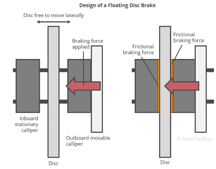
Disc brakes:
These are the basic parts of an aircraft. Similar to vehicles on the ground, aircraft also feature disc braking systems. Disc brakes are static by nature and do not revolve with the landing gear rotor. The landing gear's rotor is squeezed against by a pair of callipers that act as the disc braking system. It causes the wheels to slow down, which reduces the speed of the aircraft until it comes to a stop.
SINGLE DISC BRAKES:
Reverse Thrust:
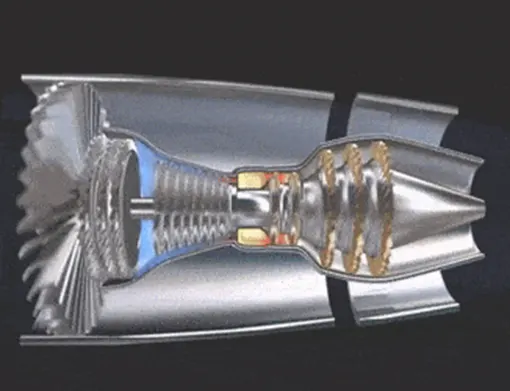
When landing, many aircraft employ reverse thrust to slow down. The engine trust's direction is changed. Typically, thrust forces air out the back of the plane to propel it forward. Therefore, thrust is projected out in front in order to stop. After landing, this is a very effective way to slow the aero plane down.
Part B:
- A. With necessary assumptions, calculate the force and power required to push / pull an aircraft by a towing vehicle.
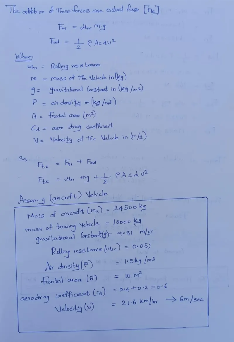
Any vehicle needs to be propelled by overcoming a number of opposing forces that are acting on it at once.
From one location to another, different forces are really applied to the vehicle.
Consider the usual runway where opposing forces are driving the car forward:
(Frr) = Force of rolling resistance
(Fad) = aerodynamic drag
Hill climbing force (Fhc) is disregarded because there is no slope.
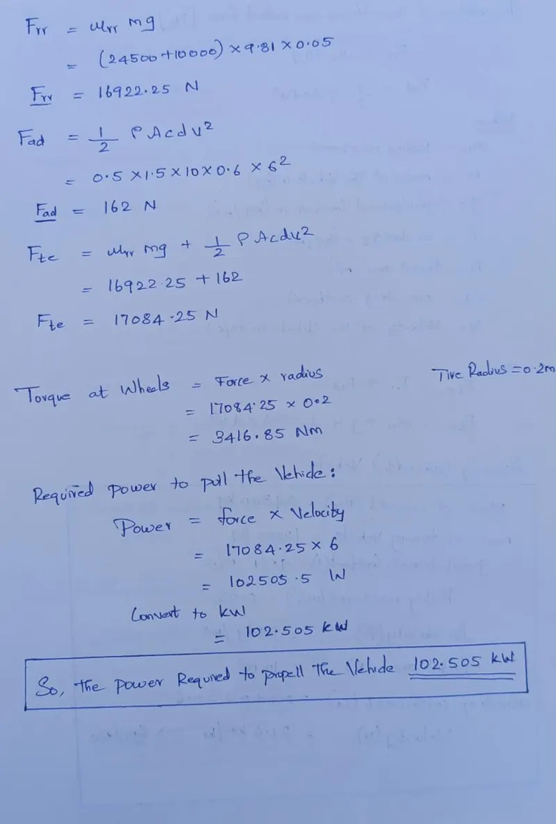
Actual or total force (Fte), the sum of these forces, is what the vehicle must overcome to move.
6.b) Develop the model for the calculated force and power using Simulink.
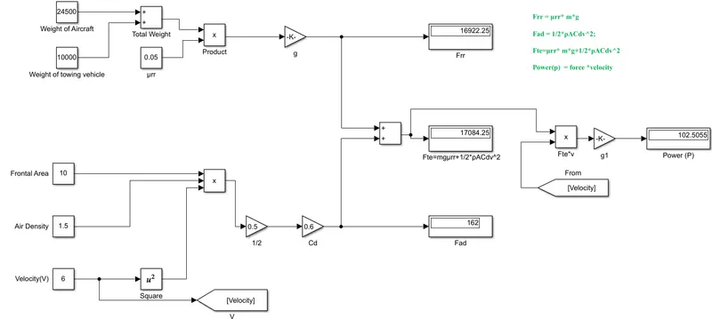
The equations that Simulink models are as follows:
One of the best tools for computing mathematical model computations is Simulink.
The model is made up of many components, including blocks for constants, gains, products, squares, and displays.
Blocks Used:
Constant block:
m- Mass of the vehicle
μrr-rolling resistance Coefficient
ρ- Air density
A- Frontal area
V -Velocity of the vehicle
Tags:
Data between the blocks is tagged using this. Go to and from
Gain block: This block is multiplying the input with the gain value.
g-gravitational constant.
Cd-aero drag coefficient
Display: Show the output of the equations, i.e., the forces and powers, as a result.
Frr=μrr mg
Fad=1/2*ρACdv2;
Fte=μrr * mg+1/2*ρACdv2
Power(p) =Force *Velocity
Working:
- The Weight of aircraft and the weight of the towing Vehicle is added by the adder block, then the Rolling resistance is given to the product block and the total weight is given to the gain block that value is displayed in the output that is Frr
- The Frontal area, Air Density and the velocity is squared and connected to the product block for multiply the output from that block is given to the two-gain block one is (1/2) and the another one is drag Coefficient and to the display block as Fad
- The Fte = Frr + Fad is connected to the product block as to find the Power.
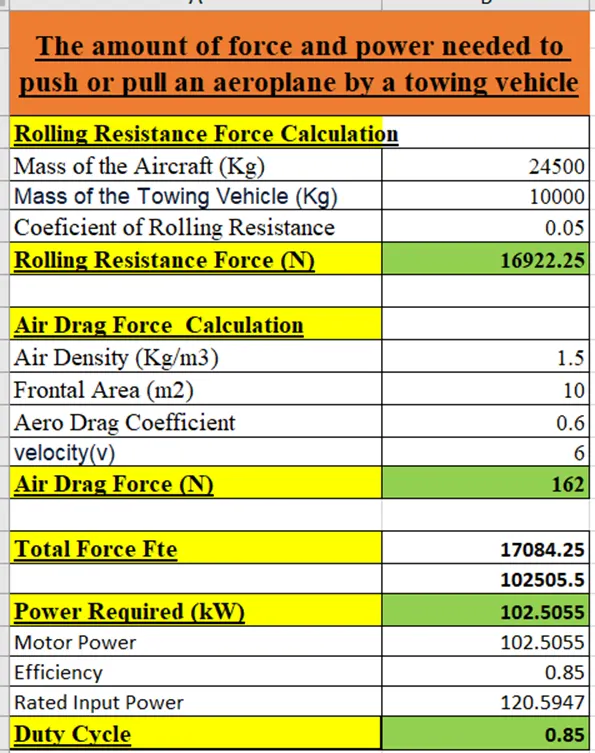
- P = Fte * v gets the output of the power 102.505 kW
Result:
- The final Display value foe the Fte is 102.505 kW (Fte=μrr * mg+1/2*ρACdv2)
- Equations are used to obtain power and force that are equal to those determined mathematically
7A.) Design an electric powertrain with type of motor, it’s power rating, and energy requirement to fulfill aircraft towing application in Simulink. Estimate the duty cycle range to control the aircraft speed from zero to highest. Make all required assumptions. Prepare a table of assumed parameters. Draw a block diagram of powertrain.
It’s power rating, and energy requirement to fulfill aircraft towing application in Simulink:
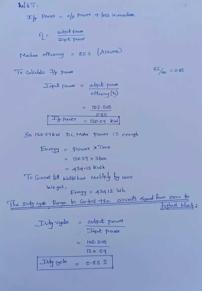
- We determined the power needed by the vehicle using the forces operating on it.
- The motor's output power is represented by this power.
- We must take efficiency into account when choosing the machine's power rating.
- The vehicle requires 102.505kw of power to move.
Due to the machine's composition of several sorts of losses:.
Draw a block diagram of powertrain:
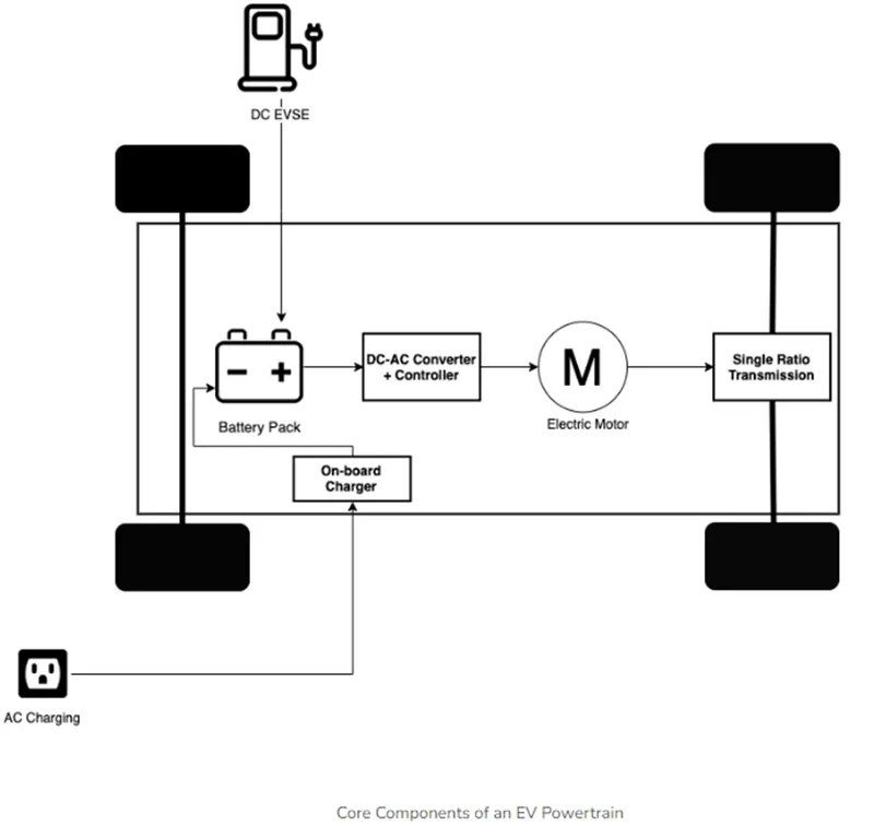
Battery Pack:
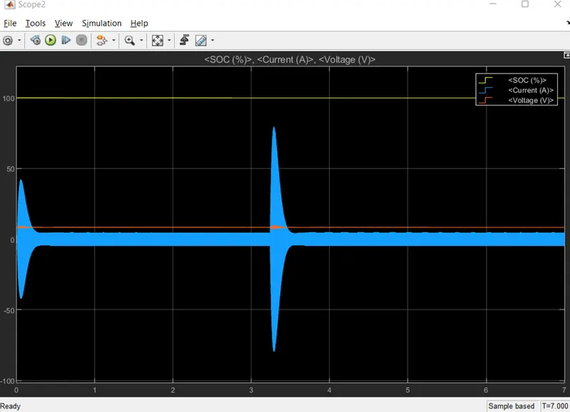
The battery pack, which is composed of many lithium-ion cells, stores the energy required to power the car. DC output is provided via battery packs.
DC-AC Converter:
The battery pack's DC energy is converted to AC and delivered to the electric motor. A sophisticated motor control system, also known as the Powertrain Electronic Control Unit, manages this power transfer by modulating the frequency and magnitude of the voltage supplied to the electric motor in order to manage the speed and acceleration in accordance with the driver's instructions transmitted via the accelerator and brake pedals.
Electric Motor:
This device transforms electrical energy into mechanical energy, which is then sent through a single ratio transmission to the wheels. Many EVs employ motor generators that can also carry out regeneration.
On-board Charger:
Regulates the amount of current flowing into the battery pack by converting AC received through the charging connection to DC
Simulink Model of Aircraft Towing Application Using DC7 Block:
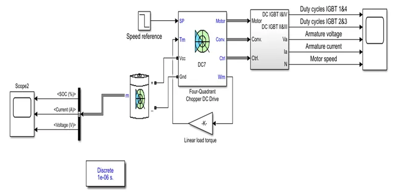
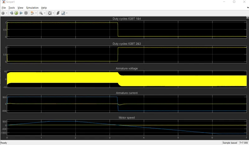
The illustration depicts the DC7 four-quadrant chopper DC drive while speed limitation is in effect.
A speed regulator is put in place first, and then a current regulator. The current controller uses the armature current reference (produced by the speed regulator) to generate the electromagnetic torque required to achieve the target speed.
To prevent abrupt reference changes that could result in armature over-current and lead the system to become unstable, the speed reference change rate follows acceleration and deceleration ramps.
By calculating the proper duty ratios of the five kHz pulses from the four IGBT devices, the current regulator regulates the armature current (Pulse Width Modulation). IGBT device 4's instantaneous pulse values must be the opposite of those of IGBT devices 2 and 3 for the system to function properly. As a result, the average armature voltage required to produce the appropriate armature current is produced.
A smoothing inductance is added to the armature circuit in order to reduce the current oscillations' amplitude.
Output: (Battery):
Prepare a table of assumed parameters:
7.B) Also, Design the parameters in excel sheet.
Conclusion:
Thus, for the above questions the Powertrain for aircraft in runways report created successfully.
REFERENCES:
https://en.wikipedia.org/wiki/List_of_airliners_by_maximum_takeoff_weight
https://www.grc.nasa.gov/WWW/K-12/airplane/move.html
https://en.wikipedia.org/wiki/True_airspeed
https://www.boldmethod.com/blog/lists/2019/11/the-four-types-of-airspeed-and-how-each-works/
https://www.aviationhunt.com/aircraft-tyre-construction/
https://www.journalofyoungphysicists.org/post/how-does-an-airplane-generate-lift-force-review
https://giphy.com/explore/takeoff
https://aerotoolbox.com/wheels-tires/
https://archive.thepocketlab.com/educators/lesson/rolling-resistance-physics-lab
https://aerosavvy.com/aircraft-wheels/
https://mediawiki.ivao.aero/index.php?title=Spoilers