Project
Introduction to Physical Modeling using Simscape
PROJECT
AIM:
The Project is to Create the Technical Report on the BAJA All – Terrain Vehicle (ATV) and to carry out the System – Level Simulation under Different conditions.
Answer:
All – Terrain Vehicle (ATV):
As defined by the American National Standards Institute (ANS I), an all-terrain vehicle (ATV), commonly known as a quad, is a vehicle that travels on low-pressure tyres, has a seat that is moved by the operator, and handlebars for steering control. It is built to handle a wider range of terrain than most other vehicles, as the name implies. Over the last decade, all-terrain vehicles have grown in popularity. All-terrain vehicles with motors are capable of cross-country movement without the use of a road or trail. An all terrain vehicle can go on land, snow, ice, marsh, swamp area, or other natural terrain depending on the tyre.
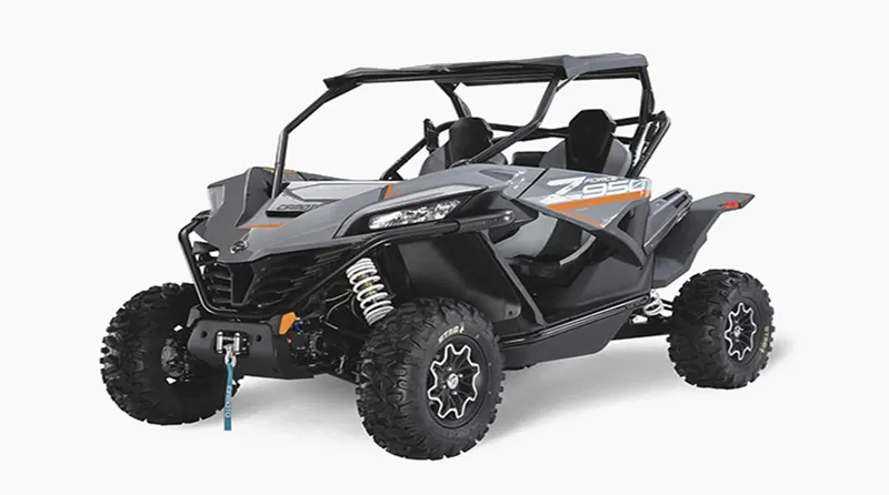
BAJA ATV (SAE):
The BAJA SAE series is a global event conducted by the Society of Automotive Engineers in the United States for undergraduate engineering students. The Mini - BAJA event began in 1976 at the University of Caroline under the moniker Mini - BAJA. The event has since expanded to six countries: The United States, Mexico, South Africa, Korea, Brazil, and India.
The BAJA SAE challenges students to design, fabricate, and validate a single-seater four-wheeled off-road vehicle to compete in a series of events over the course of three days that evaluate the vehicle's sound engineering practices, agility in terms of gradeability, speed, acceleration, and maneuverability characteristics, and finally its ability to withstand the backbreaking durability test.
CVT:
A CVT is an automatic transmission that can change seamlessly through a continuous range of gear ratios. This contrasts with other transmissions that provide a limited number of gear ratios in fixed steps. The flexibility of a CVT with suitable control may allow the engine to operate at a constant RPM while the vehicle moves at varying speeds. CVTs are used automobiles, tractors, motor scooters, snowmobiles, and earthmoving equipment.
The most common type of CVT uses two pulleys connected by a belt or chain, however several other designs have also been used at times.
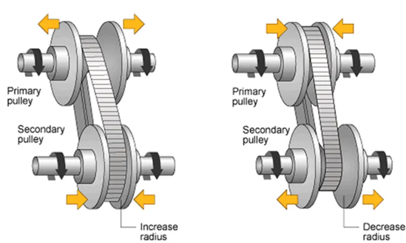
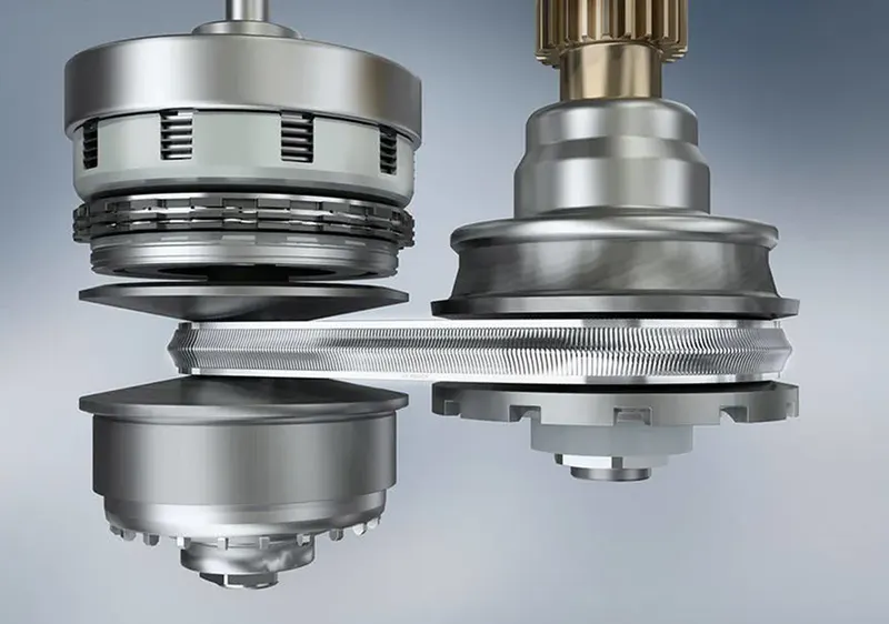
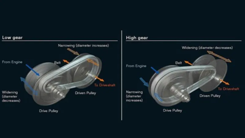
When the variator connected to the primary pulley moves outwards, the variator of the secondary pulley moves inwards, causing the radius of the primary pulley to be less than the radius of the secondary pulley, resulting in speed reduction.
When the variator connected to the primary pulley moves inwards, the variator of the secondary pulley moves outwards, causing the radius of the primary pulley to be greater than the radius of the secondary pulley,
BLOCK USED:
Generic Engine:
The Generic Engine block symbolizes a generic Internal Combustion (IC) Engine, which is a form of Spark Ignition (SI-Petrol or Compression Ignition) engine (Cl-Diesel).
The specifications for speed torque and speed power are supplied.
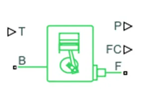
Ports:
- B - Rotational Conserving Port representing the Engine Block
- F - Rotational Conserving Port representing the Engine Crankshaft
- T - Physical signal input port specifying the normalized engine throttle level
- P - Physical signal output port reporting the instantaneous engine power, in Watts (w)
- FC - Physical signal input port reporting the fuel consumption rate, in kg/s
CVT Transmission:
CVT is explained above. And for the ports
Port:
B- Base pulley or Drive Pulley.
F -Follower pulley or Driven Pulley
R – Variable Transmission ratio that is input.
Vehicle Body:
Represents the longitudinal motion of a two-axle vehicle body. Due to acceleration and road profile, the block accounts for body mass, aerodynamic drag, road gradient, and weight distribution between axles. Each axle can have the same number of wheels or a different number of wheels. Pitch and suspension dynamics, as well as additional changeable mass and inertia, are optional. In relation to the ground, the vehicle does not move vertically.
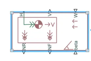
Connection H is the horizontal motion of the vehicle's body's mechanical translational conserving port. This port should be connected to the traction motion created by the tyres. The physical signal output ports V, NF, and NR are for vehicle velocity and front and rear normal wheel forces, respectively. If the wheel forces are acting downwards, they are called positive.
Physical signal input ports W and beta correspond to headwind speed and road inclination angle, respectively. The physical signal input ports CG and M are exposed if variable mass is considered. The x and y distance offsets from vehicle CG to additional load mass CG are represented by a two-element vector that CG accepts. The increased mass is denoted by the letter M. The physical signal port J accepts the inertia of the additional mass about its own CG if both variable mass and pitch dynamics are present.
Ports:
- NR - Rear Axle Normal Force (N)
- NF - Front Axle Normal Force (N)
- Beta - Road Incline Angle 9rad}
- v - Longitudinal Velocity (m/s)
- W - Head Wind Speed (m/s}
- H - Horizontal Motion
Tire:
The Vehicle Body is connected to the Tires through the axle arm, Tire is Driven according to the given input speed.
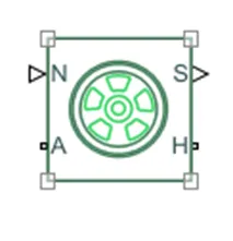
Connection N is a physical signal input port that applies the normal force acting on the tire.
The force is considered positive if it acts downwards
Connection S is a physical signal output port that reports the tire slip
Physical signal port M accepts a four-element vector corresponding to the B, C, D, and E Magic Formula coefficients.
Double-Shoe Brake:
Here we used the Double-Shoe Brake that is fixed inside the tire that’s applies the brake according to the given input.
This brake with two pivoted stiff shoes mounted symmetrically inside or outside a drum and controlled by a single actuator. The shoes exert a friction torque on a shaft linked to the drum as a result of the actuator force.
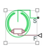
Connection S is a conserving rotational terminal associated with the drum shaft. Connection F is a physical signal port representing the force input to the actuator. Positive force creates friction torque that resists shaft rotation.
Simple Gear:
The fixed-ratio gear or gear box, no inertia is Added in this block. This block will used to vary the speed by the driver. we can define the gear ratio.
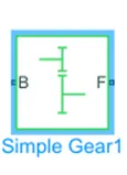
B- Base Gear
F- Follower Gear
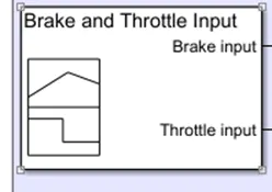
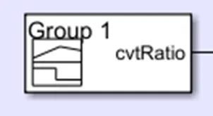
Signal Builder:
This used to generate the signal for the Brake input, Throttle Input and the CVT.
Solver Configuration:
This is used to Solve the Parameters given in the block.
Mechanical Reference:
This block represents a mechanical rotational reference point, that is, a frame or a ground. Use it to connect mechanical rotational ports that are rigidly affixed to the frame (ground).

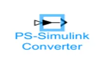
PS to Simulink Converter:
This is used Converts the input Physical Signal to a Simulink output signal.
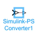
Simulink to PS Converter:
This is used to Converts the Simulink input signal to a Physical Signal.
Generic Engine:
This is used to run the engine at the various speed and Torque by the given input.
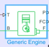
Where,
T – Throttle
F & B - mechanical rotational conserving ports
P & FC - are physical signal output ports
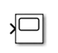
Scope:
Scope is use to plot the outpu results of the various parameters that given by the input signal, so we can compare the results for Engine Rpm, Velocity, Displacement, Throttle, Brake and the CVT Shaft speed.
Inertia:
The block represents an ideal mechanical rotational inertia.
The block has one or two mechanical rotational conserving ports. The difference is purely graphical, as the ports are rigidly linked. The block positive direction is from its port to the reference point. This means that the inertia torque is positive if the inertia is accelerated in the positive direction.
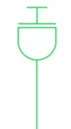
Variable Gear Ratio:
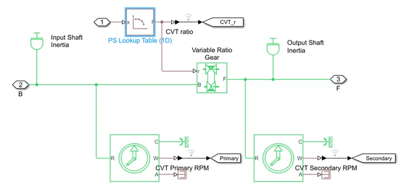
Represents a variable ratio gearbox such as implemented by mechanical belt CVT, electric, or hydraulic transmissions.
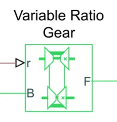
The physical signal input r defines the ratio of input to output angular shaft velocities. Connections B (base) and F (follower) are mechanical rotational conserving ports. Specify the relation between base and follower rotation directions with the Output shaft rotates parameter.
Ideal Rotational Motion Sensor:
In a mechanical rotational network, this block measures angular velocity or angle. The sensor is perfect since it ignores inertia, friction, delays, energy consumption, and other factors.
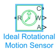
The angular velocity and angle of port R relative to port C are reported by the physical signal ports W and A, respectively. When the angular velocity at port R is larger than the angular velocity at port C, the observed angular velocity is positive.
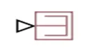
PS Terminator:
To terminate physical signal outputs, use this block. Unconnected physical signal output ports do not generate warnings, but connecting to a PS Terminator can indicate that the signal was not left unconnected inadvertently.
PS Constant:
This block creates a physical signal constant:
The Constant parameter accepts both positive and negative values.
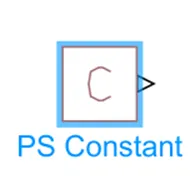
The block output is a physical signal port.
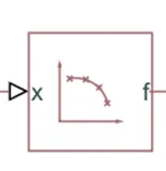
Lookup Table:
This block illustrates a physical signal converter with a lookup table that specifies the input-output relationship. The table grid must be arranged in exact ascending or descending order, although the spacing can be uneven.
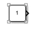
Constant:
Use this block to provide a constant signal input. Constant block generates a real or complex constant value signal.
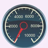
Circular Gauge:
This is used to measure the input given from the Knob for the Throttle and the brake input.
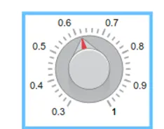
Knob:
Set a value to tune parameters or variables. Is use for the brake and the throttle input.
BAJA ATV MODEL WITHOUT DASHBOARD
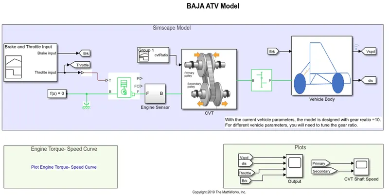
- BAJA ATV Model contains main Blocks are Generic Engine, engine sensor, CVT, Simple Gear, Vehicle body.
- Here for Brake and the Throttle input is created with the signal builder block the brake = 0 & Throttle = 0.5 initially, it is given to the Generic engine.
Generic Engine:
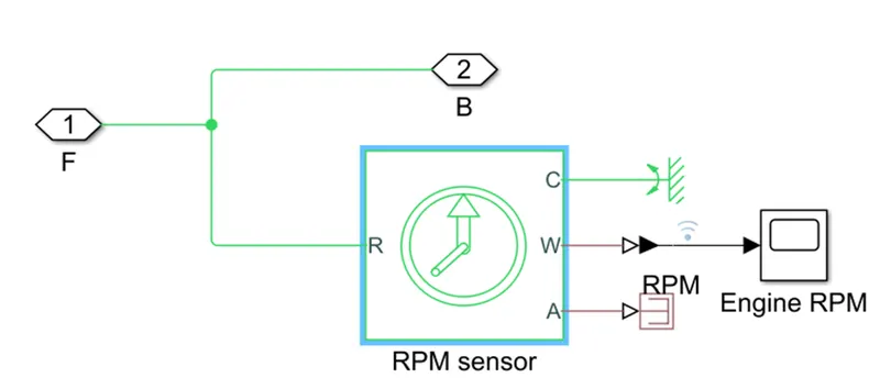
- T point and another end point of engine is connected to the engine sensor inside that contains Ideal rotational motion senor is used to monitor the speed of the engine rpm and is Monitored by connecting the Scope to the W point of the Engine Sensor through scope.
CVT Block:
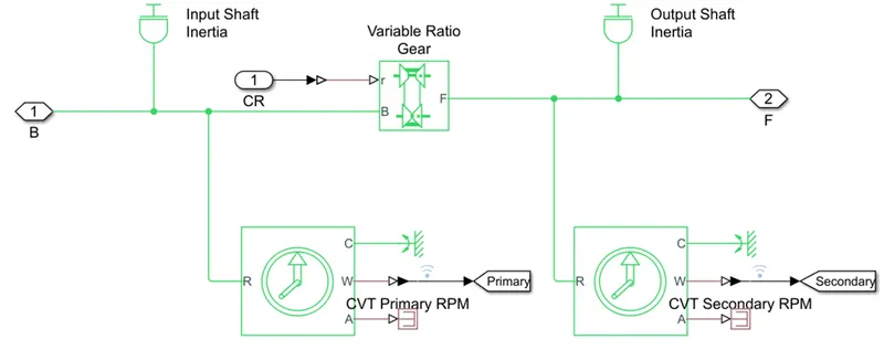
- The Engine Sensor the other end is connected to the CVT block includes, Variable Gera Ratio by connecting the Simulink – PS converter, there is
Primary and the secondary Pulley for CVT; called Drive Pulley and Driven pulley, the pulley will increase or decrease the radius according to the Speed of the engine.
Vehicle Body:
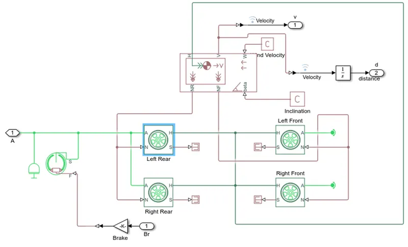
- The Input inertia and the output inertia is also connected for the initial condition. The Simple gear is connected to the CVT and the other end is to the Vehicle body that includes tire, Double Shoe brake, Vehicle body block,
- Here the port H is the mechanical translational conserving port associated with the horizontal motion of the vehicle body. Connections V, NF, and NR are physical signal output ports for vehicle velocity and front and rear normal wheel forces, respectively. Wheel forces are considered positive if acting downwards. Connections W and beta are physical signal input ports corresponding to headwind speed and road inclination angle.
- The Wheels are attached to the Vehicle body moves according to the Speed input given
- The Velocity is integrated to get the distance and monitored in scope,
- The Double Shoe brake, used to control the Speed of the vehicle that is attached to the tires, the gain for the is 1000
- Here the Input inertia is added to be in the initial state.
Simulation:
Input (Signal Builder):
Throttle Input
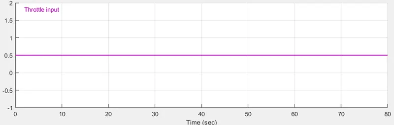
Here the Throttle input given is 0.5 by the Signal Builder.
Workspace input:
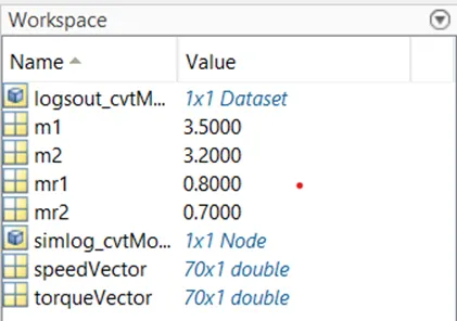
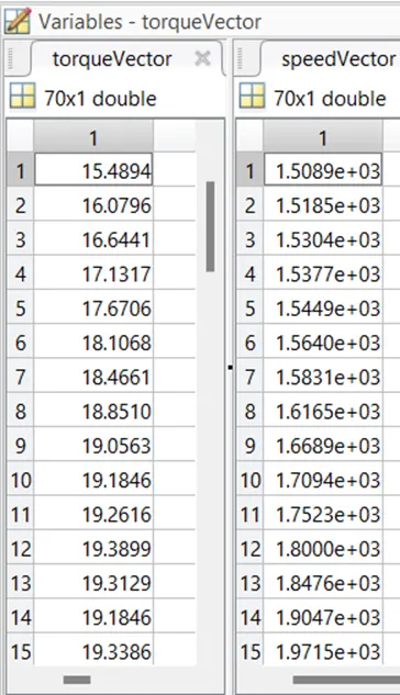
The Speed Vector and the Throttle input are given in the Workspace.
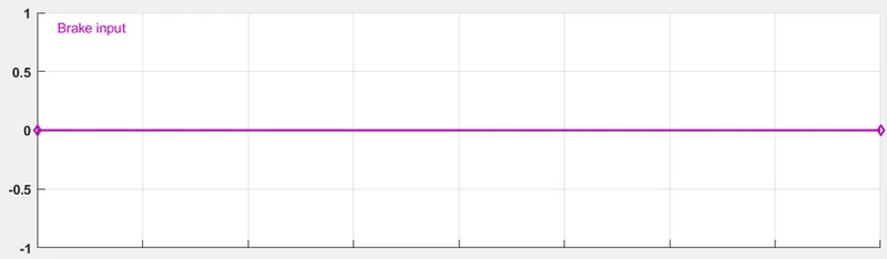
Brake Input:
This is used to apply the Brake to the wheels the default value is '0'.
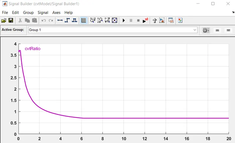
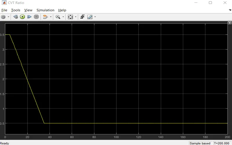
CVT Ratio:
The output of the CVT Ratio is given to the CVT Block by the use of the signal builder.
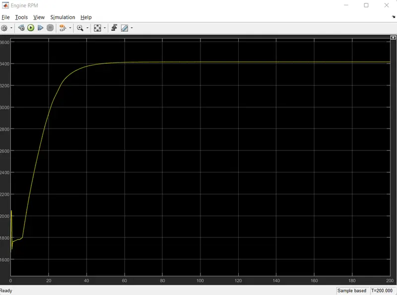
Engine Sensor:
The Ideal Motion Rotational sensor is used to measure the engine speed and the port W is connected to the scope to measure the engine speed.
Here the Maximum RPM =3415
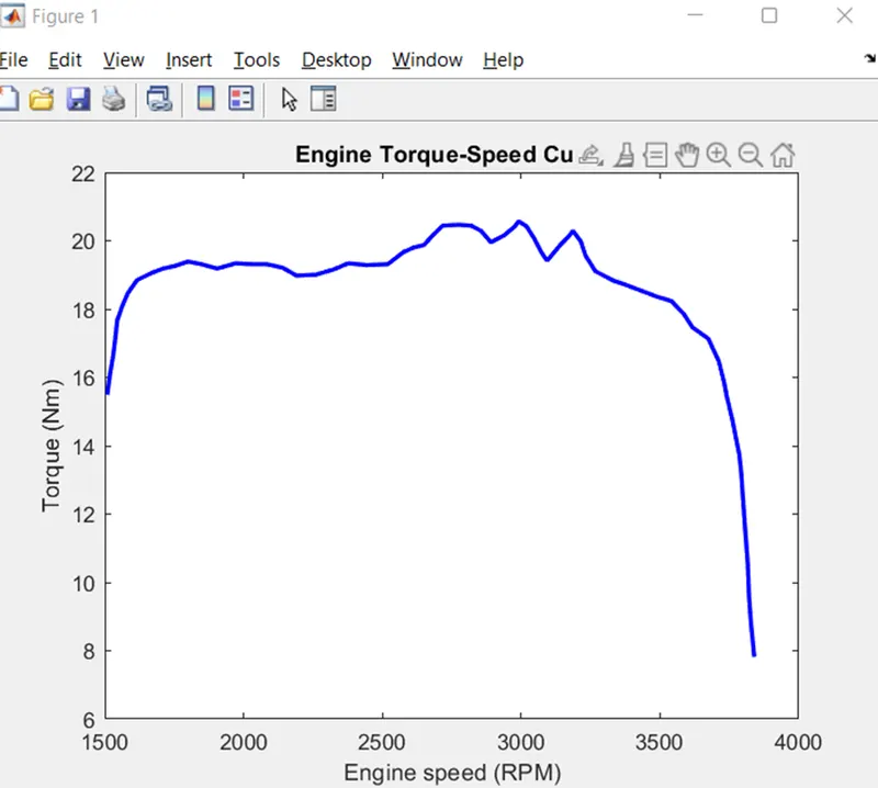
Engine Torque- Speed Curve:
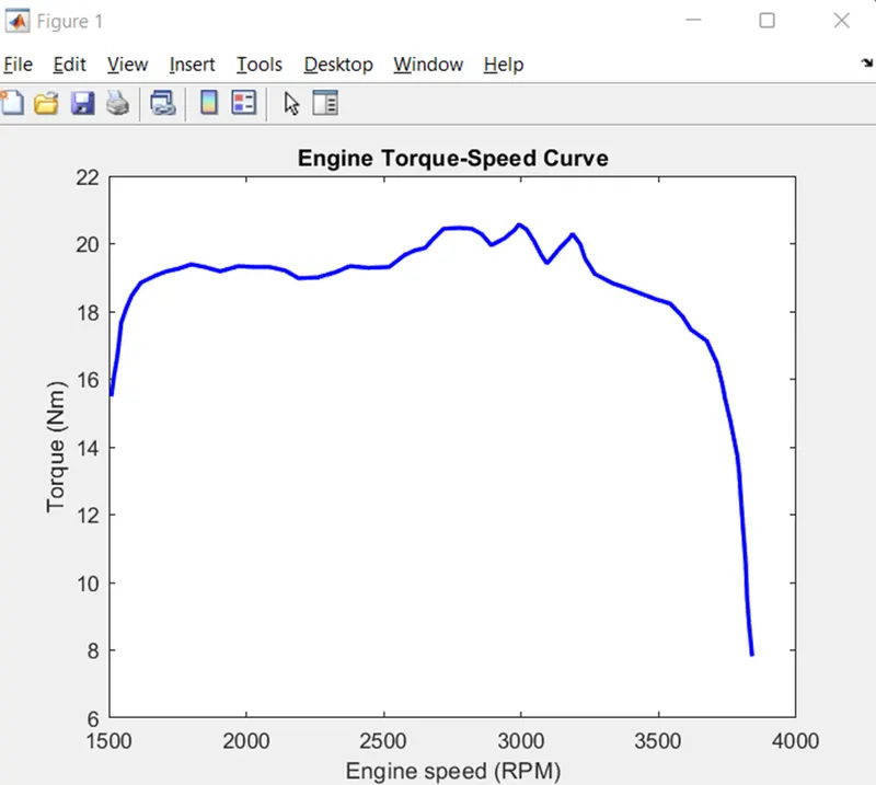
Torque and the speed are input from the MATLAB workspace window as shown earlier, this will generate the output RPM according to the input.
OUTPUT:
SCOPE:
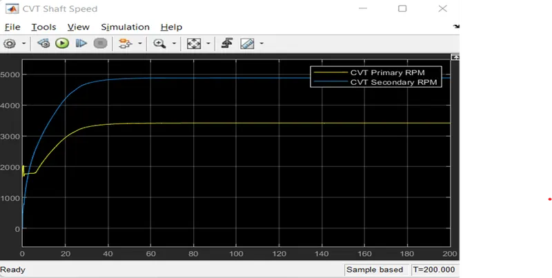
CVT Shaft Speed:
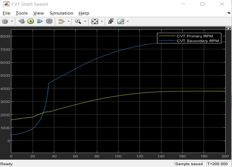
This will Measure the Speed of the CVT shaft of the Primary and Secondary.
SCOPE:
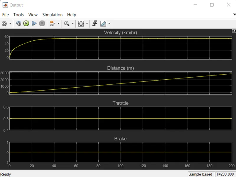
Results for the Velocity, Distance, Throttle, Brake:
BAJA ATV MODEL WITH DASHBOARD
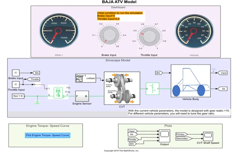
In this Model they added the brake and the throttle input by the constant block instead of the Signal Builder,
In the Dashboard Knob input is added to vary the Brake and the Throttle input, this is connected to the Constant Block of brake and throttle that is linked to the Generic engine.
Initial condition to run the simulation
Brake input=0
Throttle input=0.5.
While Running the Simulation the throttle and the Brake knob is varied and the different cases of output is noted.
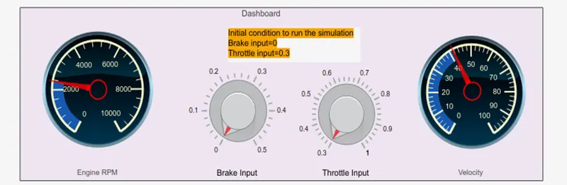
The Circular Gauge Rpm is connected to the Engine Sensor block and the velocity gauge is connected to the velocity block of the Vehicle body block.
Engine Torque vs Speed Curve:
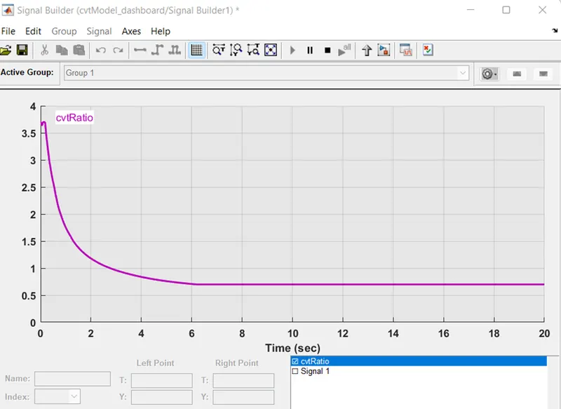
CVT RATIO:
This is input to the CVT block by the use of the Signal builder.
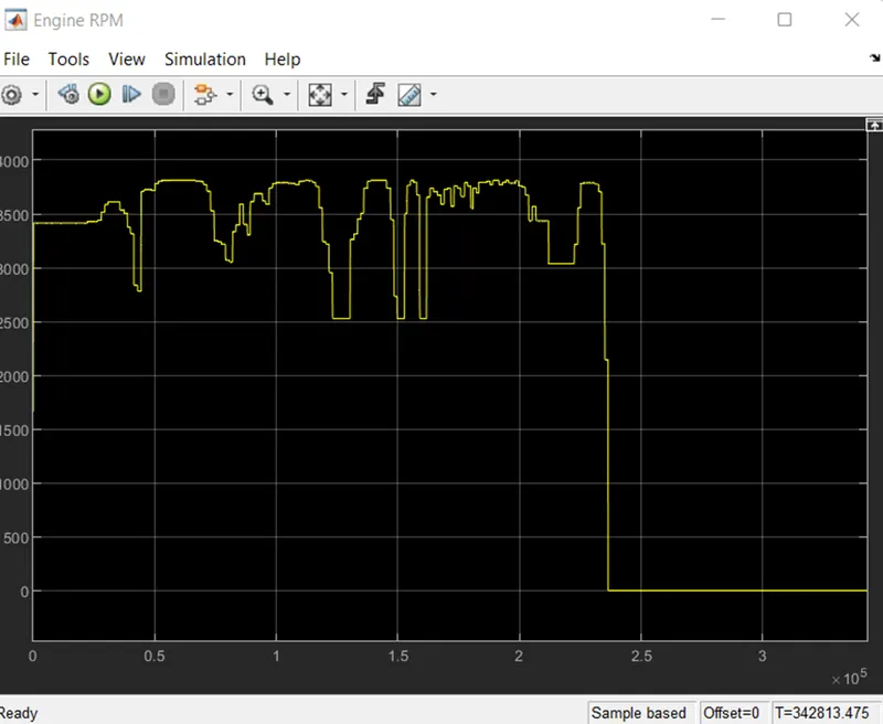
Engine Sensor
(Scope) Output:
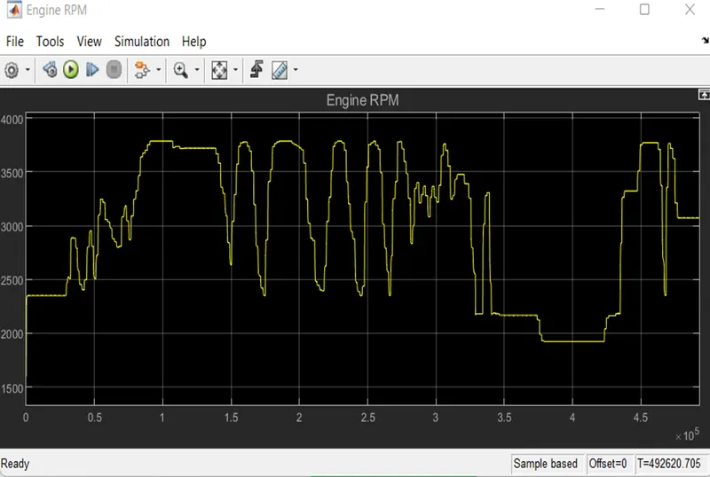
This the Engine Rpm that is Varied through the Throttle Knob.
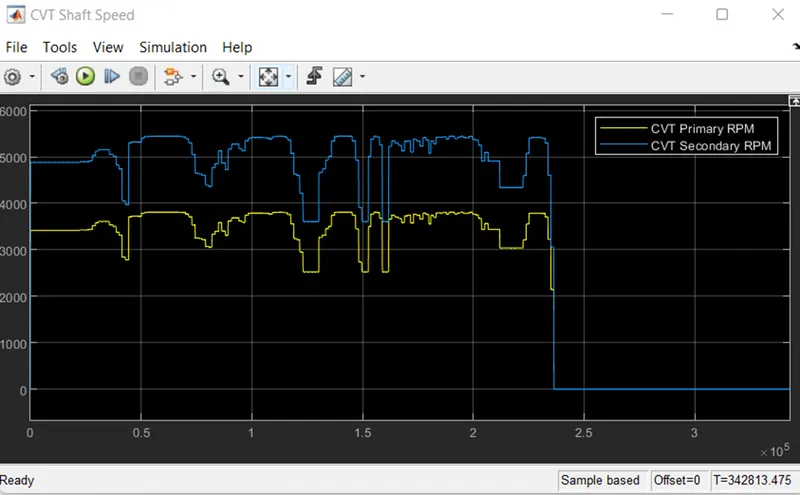
CVT Shaft Speed:
This output Obtained form the CVT block which contains the Primary and the Secondary shaft that will Obtain speed according the to the given Speed from the Throttle.
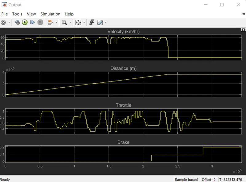
Scope Output:
Results for the Velocity, Distance, Throttle, Brake:
The Velocity is integrated to get the Result of the Distance is plotted in the graph.
When the brake is applied further the rpm will reduced to zero.
When we increase the throttle knob there won’t be any changed in the engine rpm.
Turn Off the simulation and note the further outputs.
BAJA ATV MODEL – MAPPED LOOKUP TABLE
WITHOUT DASHBOARD:
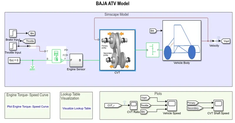
Here instead of the Signal Builder the lookup table is added to the CVT Block.
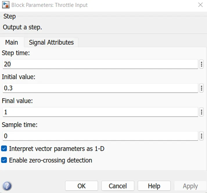
And the Step block is used for the Throttle and the Brake.
The velocity is given back to the CVT block, by the use of the lookup table.
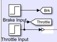
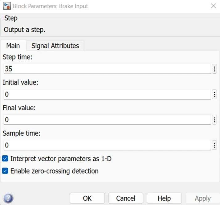
For the Step Brake:
For the Step Throttle:
CVT BLOCK:
Lookup Table:
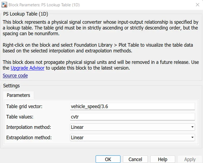
A lookup table is a collection of data that approximates a mathematical function by mapping input values to output values. A lookup operation obtains the relevant output values from a table given a set of input values. Simulink can estimate an output value via interpolation, extrapolation, or rounding if the lookup table does not clearly indicate the input values.
A lookup table block approximates a mathematical function by mapping input values to output values using an array of data. Simulink conducts a "lookup" operation on the input values to extract the appropriate output values from the table. The block guesses the output values based on nearby table values if the lookup table does not define the input values.
In the models below, a lookup table is used in place of CVT ratio input. It must be loaded into a workspace with the name Lookup table data. Mat as the file name.
LOOKUP TABLE:
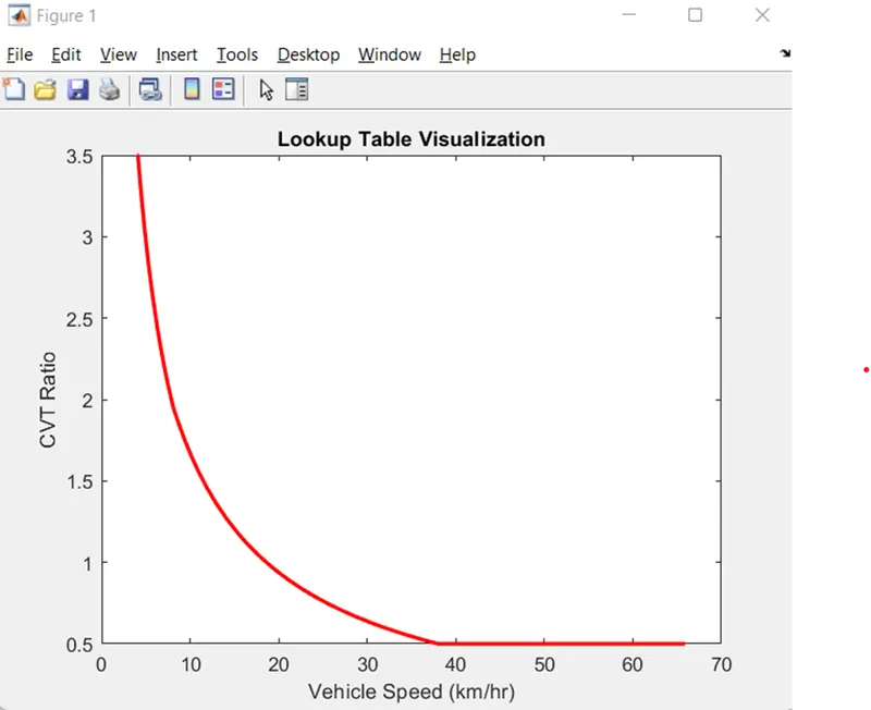
CVT Ratio vs Vehicle Speed:
WORK SPACE:
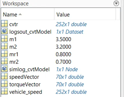
From the previous some more added are vehicle speed and the cvtr in the workspace.
OUTPUT:
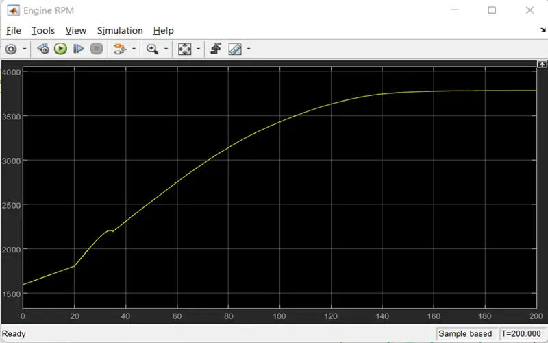
ENGINE RPM:
CVT RATIO:
CVT SHAFT SPEED:
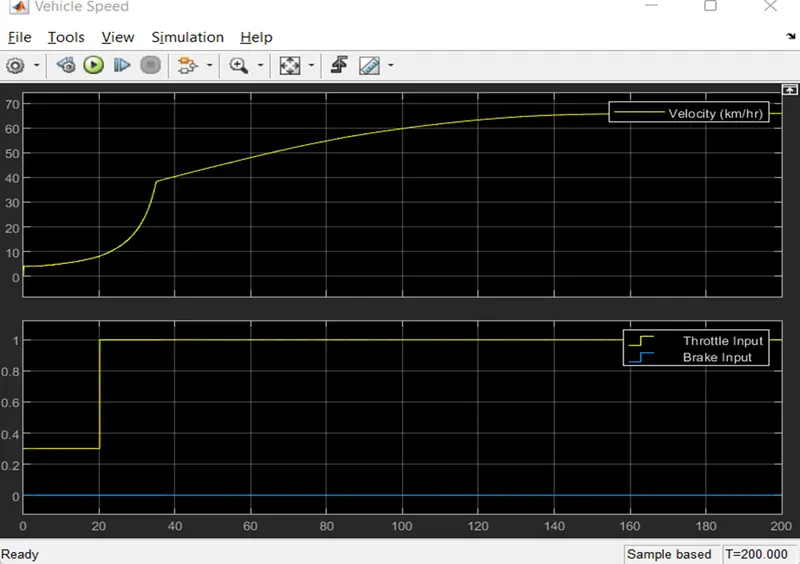
VEHICLE SPEED:
BAJA ATV MODEL – MAPPED LOOKUP TABLE
WITH DASHBOARD:
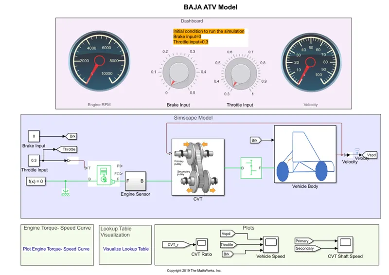
Here the same lookup table is used for the CVT Block and for the Engine for the previous we used the Step block instead of. with dashboard model here, we are using the constant block that are connected to the circular gauge and the Knob.
While using the dashboard model the stop Time is set to the inf
When the (Simulation is ON):
ENGINE RPM:
CVT RATIO:
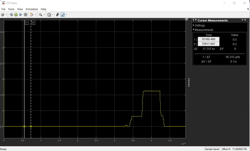
For the plot from the CVT Ratio the curser measurement is shown on the right side of the plot.
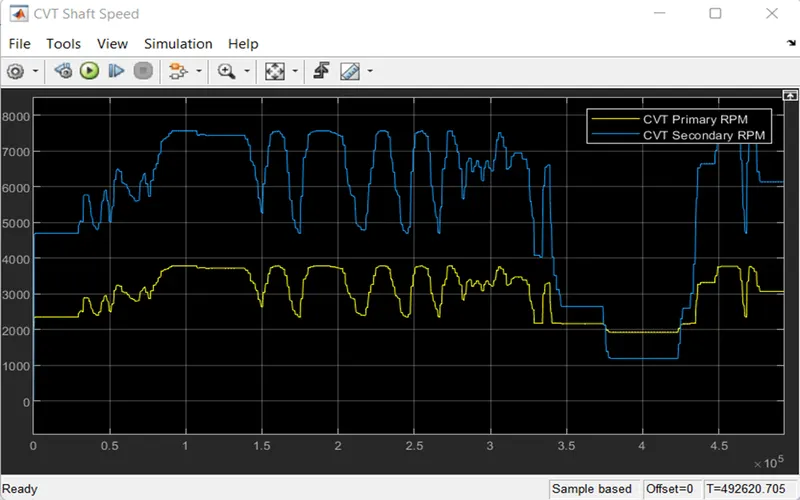
CVT SHAFT SPEED:
This graph shows the CVT Shaft speed of the primary and the secondary RPM.
VEHICLE SPEED:
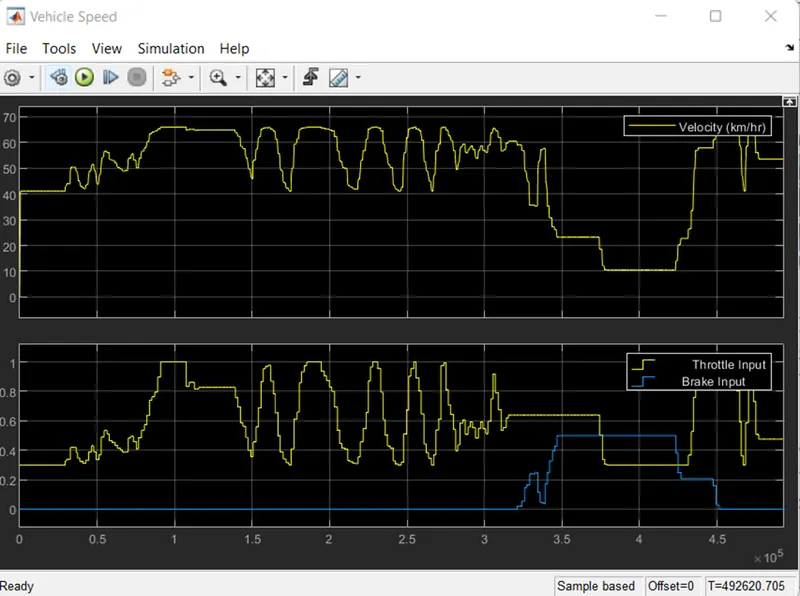
PLOTS For velocity, Throttle input & Brake Input:
Here we can see in the graph when the brake is ‘0’ the throttle we apply the Velocity increases
As the brake apply for some extent the velocity is decreased as showed.
CONCLUSION:
The simulation of all four models of BAJA ATV vehicles has been completed, and the outcome for each model has been plotted by altering the input data.