Project - 2 - Meshing on the suspension Assembly
Aim:
To mesh the given rear wheel assembly to given quality criteria and to provide the appropriate connections to the parts.
Procedure:
1. Import the model into ANSA work space, and separate the parts by applying individual PIDs to all the parts
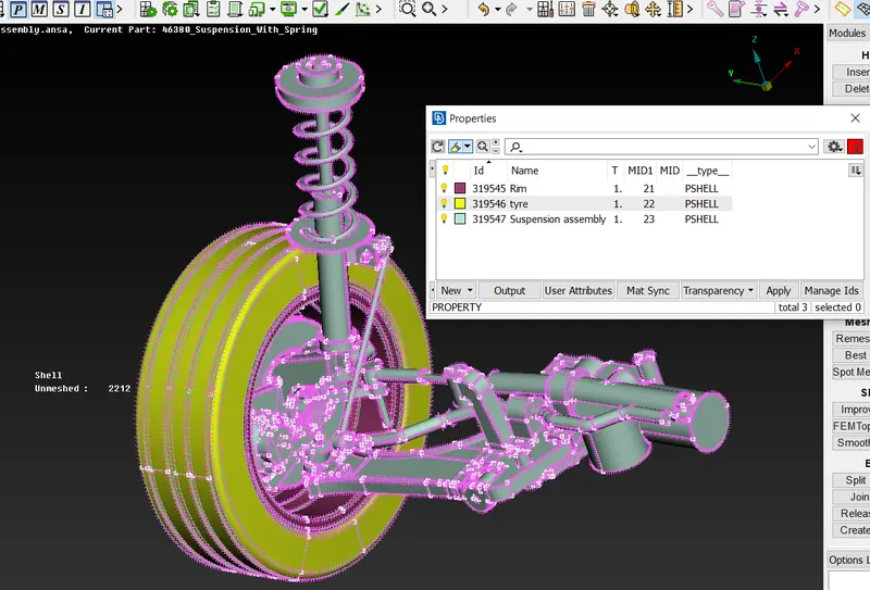
Fig 1: given model with just 3 PIDs applied.
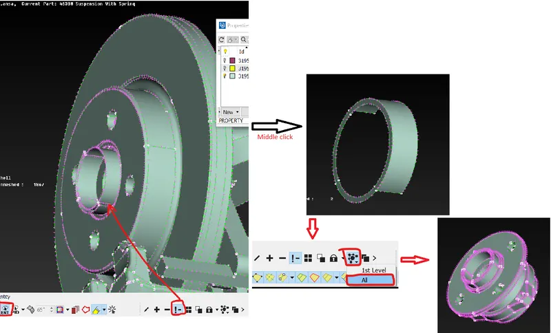
Create new PID and apply to the part.
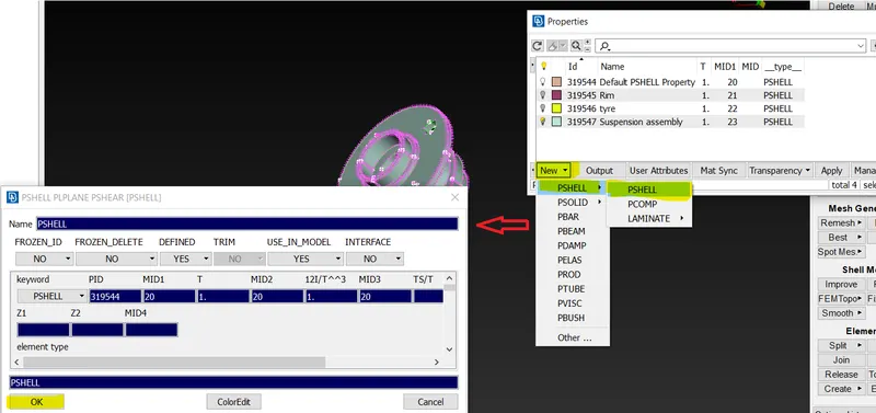
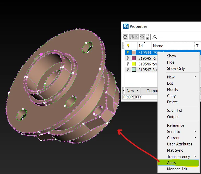
Repeat the same for all the different parts in the model and apply new PID to all
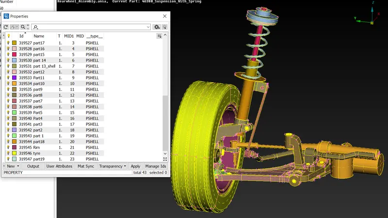
Model after separating all the parts.
3D Meshing of tyre and rim parts:
Set the quality criteria for the surface meshing as per the given criteria for surface meshing with tria element.
|
Target/Average length |
6.5 |
|
|
Minimum Length |
5 |
|
|
Maximum Length |
10 |
|
|
Skewness |
45 |
Use Spot-mesh option to mesh the part.
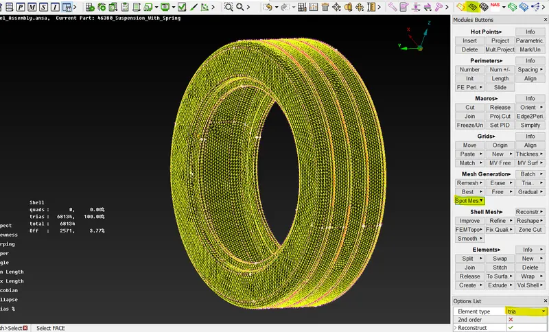
Converting it to the solid mesh
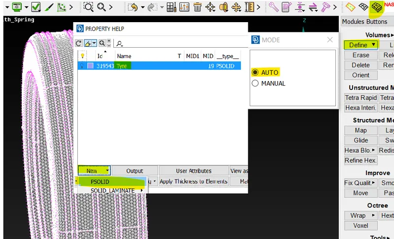
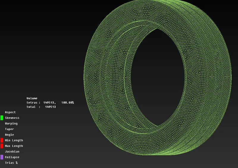
Solid elements with zero elements failing for tet collapse.
Repeat the above steps for all other parts which have variable thickness and thickness above 5 mm.
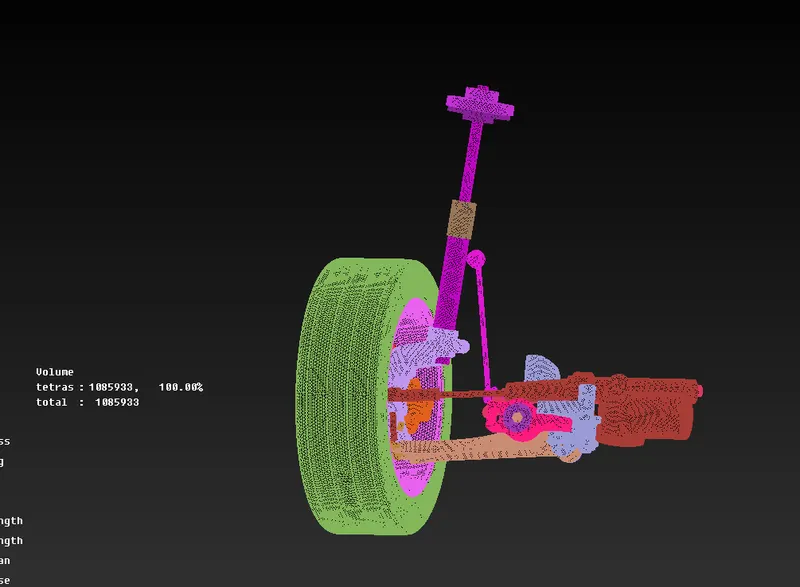
Volume mesh of all the parts with zero elements failing f ortet collapse.
Shell meshing of parts with thickness less than 5 mm:
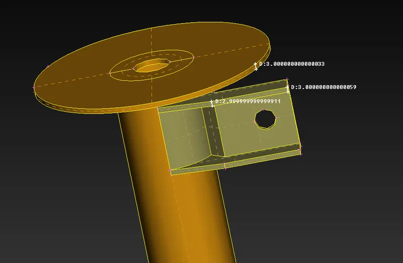
Both the above parts have thickness less than 5mm, mid-surface needs to extracted to mesh thses parts.
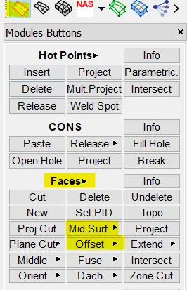
Use mid-surf or offset option from TOPO module to extract the mid-surface.
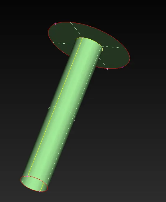
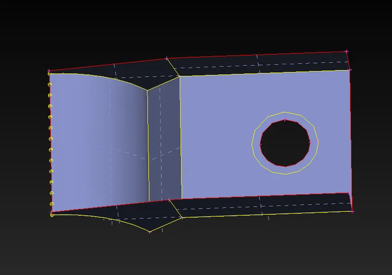
Mesh the parts with hexa elements.
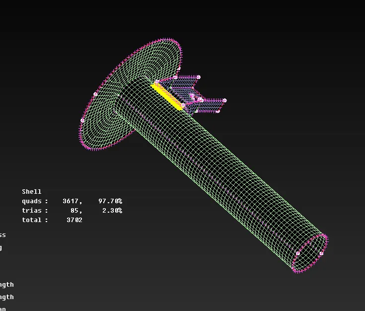
Shell elements with zero failed for quality criteria.
Modelling of spring element :
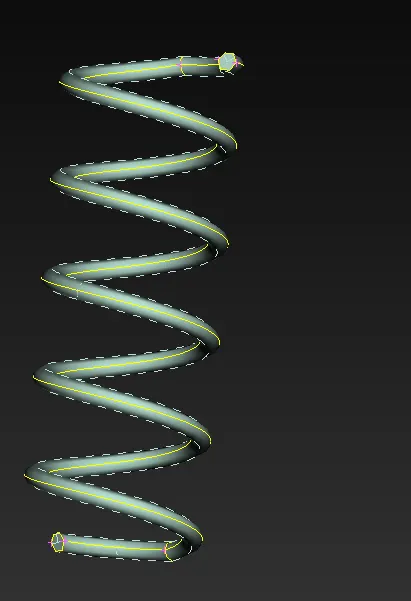
Extract the mid-curve for the spring element. Using middle option from topo module.
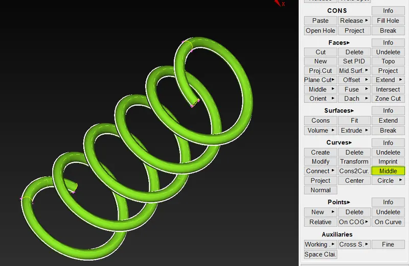
Extract the mid-curve for the spring element. Using middle option from topo module. Connect the curve into single entity as shown below.
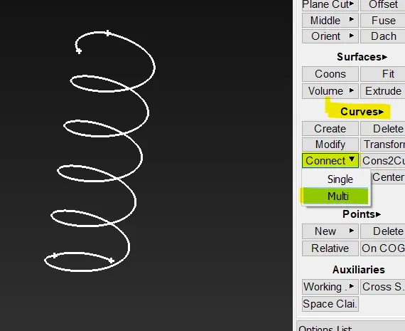
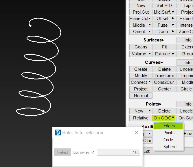
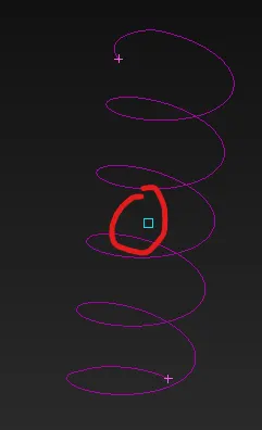
switch the module to Decks and select NASTRAN.
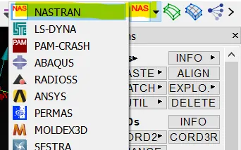
Select the CBAR option from elements and switch on orientation with nodes and set the selection to curves as shown below.
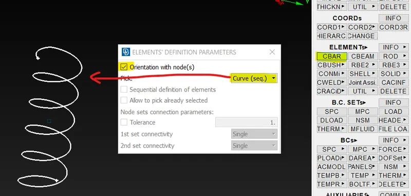
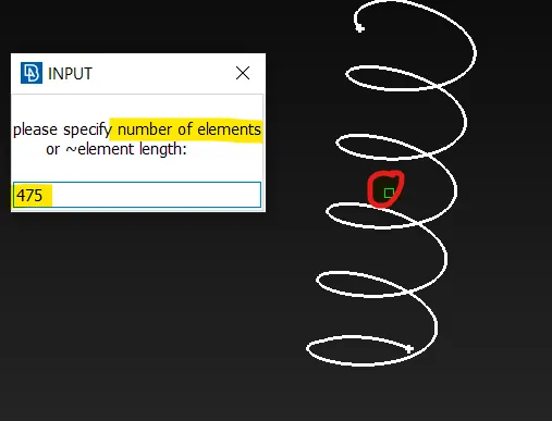
Select the COG point for node orientation and enter the number of elements needed capture the spring.
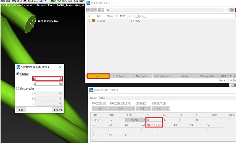
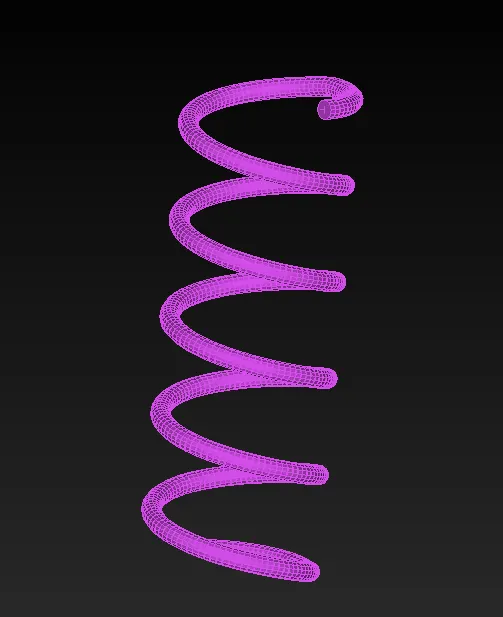
Click ok, property help window will open, select new and take the cursor to A (area) option and press SHIFT + ?, section parameter window opens enter the radius of the spring and click ok and again ok on PBAR window, open the PBAR property created and again press ok the spring element will be created.
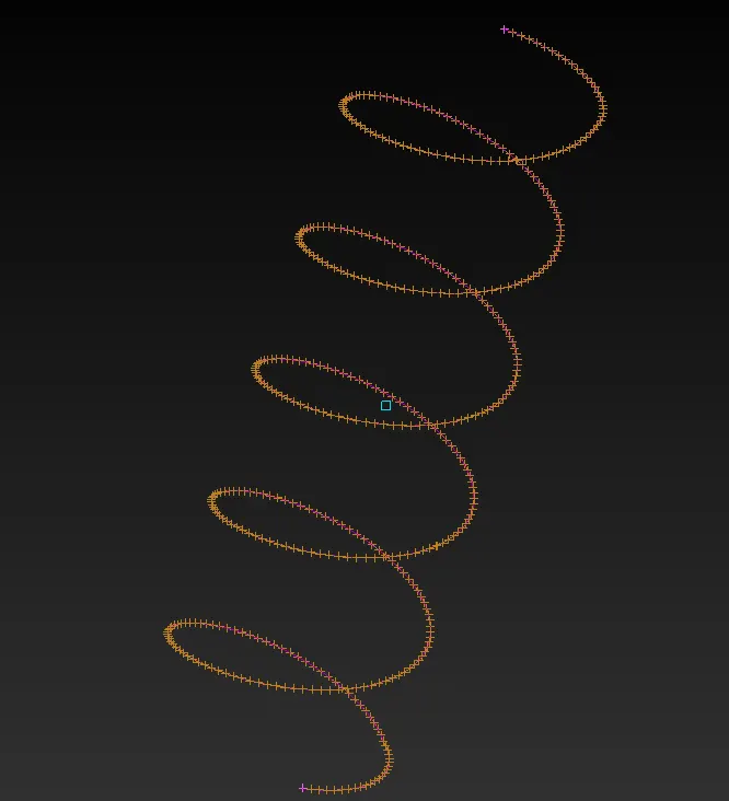
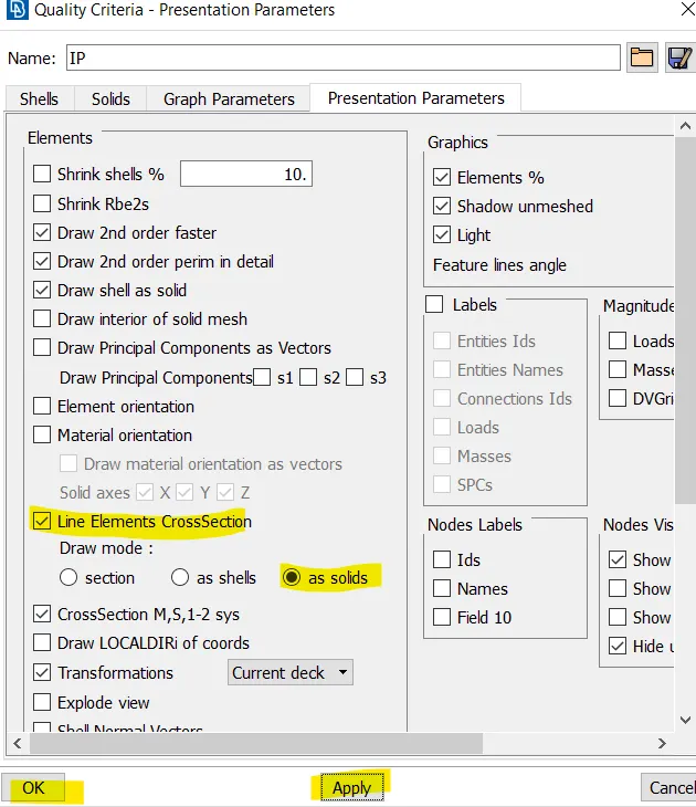
to view line element as solid switch on the following option in presentation parameters.
Creating connections :
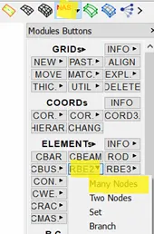
Bolts are represented by RBE2 elements in the model, go to DECKS module. Elements > RBE2 to create connections to represent bolts.
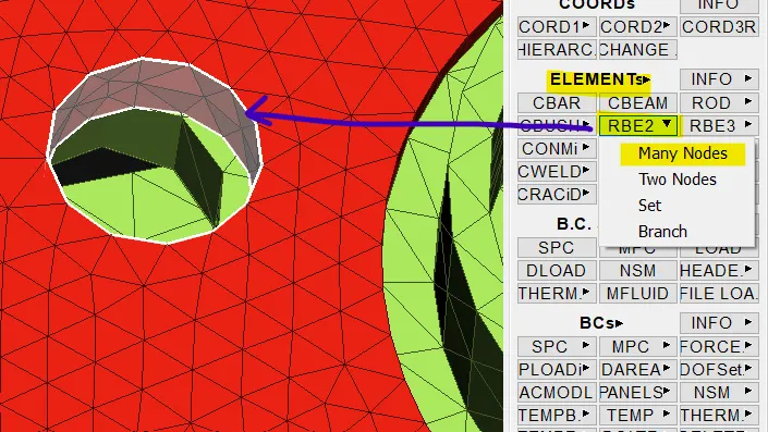
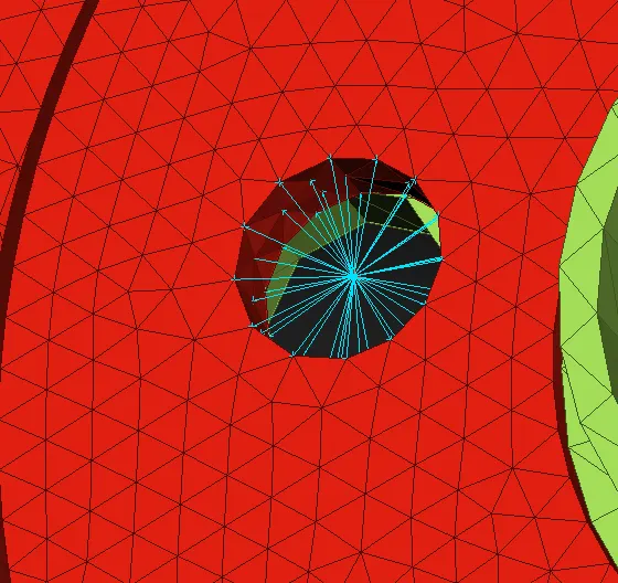
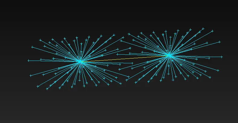
Similarly RBE2 elements are created on the opposite part and connected using RBE2 two nodes option
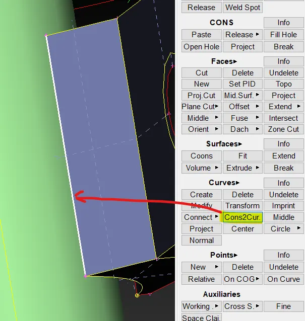
seam connection :
To create a seam connection a curve needs to be defined which acts as a seam line for the connection
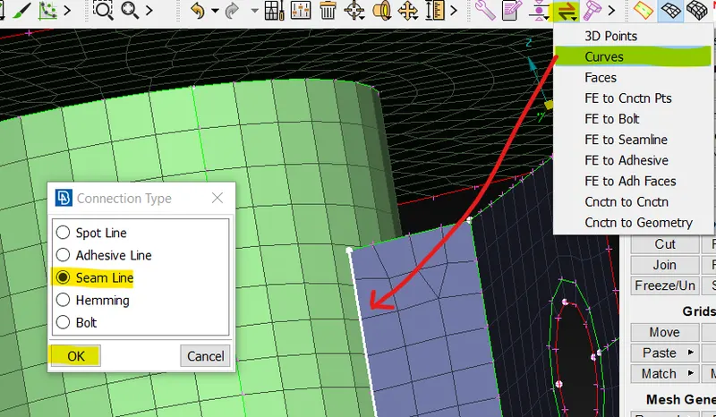
Convert the curve to seam line: ASSEMBLY > CONVERT > CURVES > SELECT THE CURVE > SEAM LINE > OK
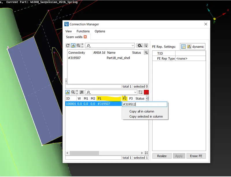
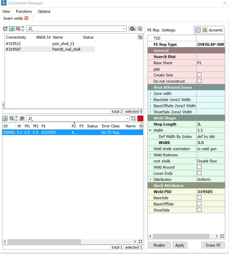
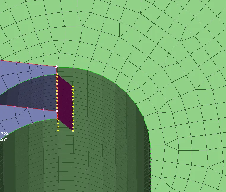
final model with all the connection.
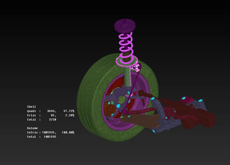
Reflecting the model on the other side to complete the assembly.
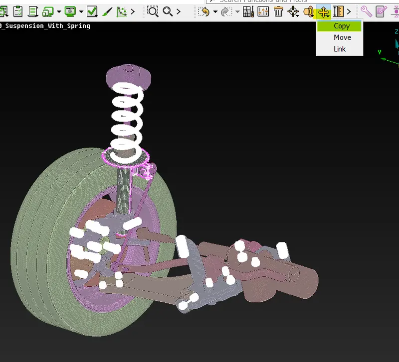
select all the parts and connection in the model.
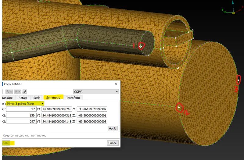
select 3 points plane and select the points circled in red and apply.
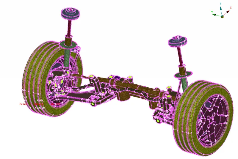
final model with connections.
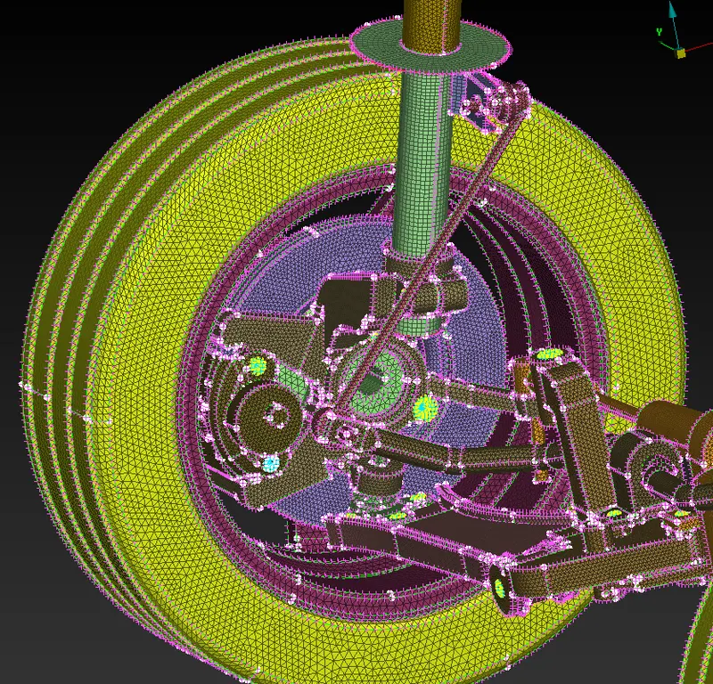
Learning Outcomes:
Separating parts by applying PID, Surface meshing with tria elements, volume meshing, mid-surface generation, connections like RBE2 and seam weld, modelling of 1D elements like spring using CBAR option, reflecting the model
Conclusion:
The given rear wheel assembly is imported into ANSA and meshed using shell elements and converted to solid elements using volume module, bolts are modelled using RBE2 elements and overlap shell is used to connect the shell parts.