Project 1- Traffic Jam Assistant Feature
AIM: To develop a single feature of Traffic Jam Assistant algorithm using MATLAB & SIMULINK.
OBJECTIVE:
1. Model development as per MBD guidelines.
2. Creation of Simulink Data Dictionary (SLDD) file
3. Code Generation using Embedded Coder
4. Generate Model Advisor Report
INTRODUCTION:
Traffic Jam Assistant is one of the most common feature in Advanced Driver Assistance System. Traffic Jam Assistant helps the driver arrive more relaxed at their destination, even in dense traffic or in traffic jams. As a partially automated comfort function, the system takes over the longitudinal & lateral guidance of the vehicle. This means that the car can drive off, accelerate & brake automatically, as well as steer the vehicle within certain constraints. The driver has to permanently supervise the system & be ready to take over the complete control of the vehicle at any time.
Traffic Jam Assistant system helps to avoid rear end collisions in dense traffic conditions & traffic jams. In Traffic jams, the vehicle takes over driving off, acceleration, braking and steering within same lane.
Basic Working Principle:
Traffic Jam Assistant is based on the sensors and the functionality of the Adaptive Cruise Control (ACC) with stop & go and Lane Keeping Support (LKS). When ACC ‘Stop & Go’ is turned ON, the Traffic Jam Assistant continuously analyses the speed of the surrounding vehicles and compares it with the own driving speed. If the system detects dense traffic or a traffic jam at speeds less than 60 kmph, the driver can activate the functionality by press of a button. The vehicle will now automatically follow the vehicle in front, takes over driving off, acceleration, braking and steering within same lane.
Information regarding the Traffic Jam Assistant will be available to be displayed to the driver in the Instrument Panel Cluster (IPC). The Algorithm which the students need to implement here in this project is predominantly based on IPC units.
SOLUTION:
There are certain requirements given in the problem to implement the model Traffic Jam Assistant. The following are the steps followed:
1. Create the Simulink Data Dictionary(SLDD) file from given data, carefully declare the inputs and outputs in SLDD file.
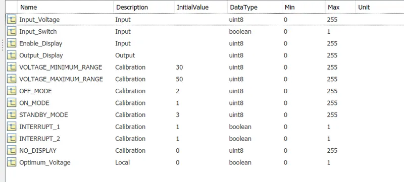
SLDD file is attached for reference.
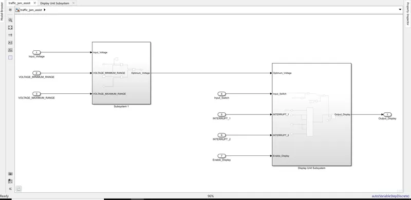
2. As per REQUIREMENT -1:
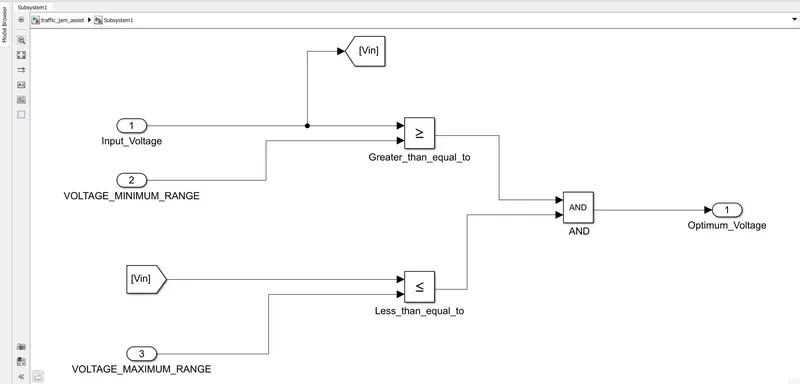
- Input Signal “Input_Voltage” is compared against voltage values “VOLTAGE_MINIMUM_RANGE” & “VOLTAGE_MAXIMUM_RANGE”.
- Incoming input signal “Input_Voltage” must be greater than – equal to “VOLTAGE_MINIMUM_RANGE” and less than – equal to “VOLTAGE_MAXIMUM_RANGE”.
- Output signal from here is “Optimum_Voltage” which will be one of the inputs to the subsystem “DisplayUnit”.
It is implemented as:
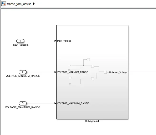
Subsystem consists of :
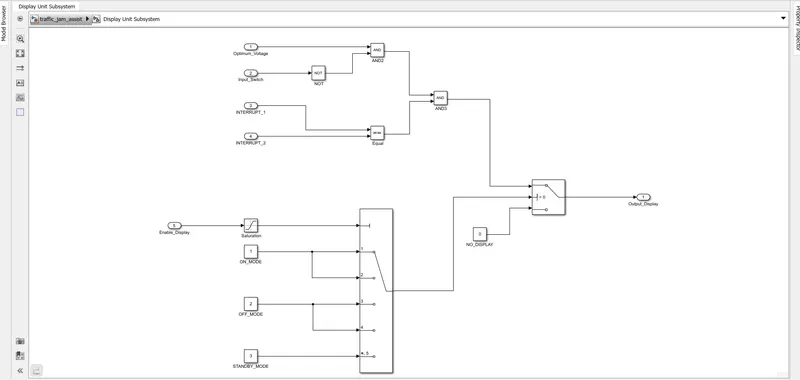
3. As per REQUIREMENT No 2 (DisplayUnit Subsystem):
- Input Signals are “Optimum_Voltage”, “Input_Switch”,“Enable_Display”. Signal “Enable_Display” must be saturated between the range 0 – 7. Output signal from the subsystem is “Output_Display”.
- Input Signal “Enable_Display” is compared against pre – defined set of values in a multiport switch. Total data ports in the multiport switch is 5.
- Multiport switch inputs 1 & 2 is connected to calibration signal “ON_MODE”, Multiport switch inputs 3 & 4 is connected to calibration signal “OFF_MODE” while Multiport switch input 5 is connected to calibration signal “STANDBY_MODE”.
- The output from Multiport switch is connected to the first input port of the Switch block. The third input port of the Switch block is connected to the calibration signal “NO_DISPLAY”.
- Meanwhile NOT value of input signal “Input_Switch” is compared in an AND gate against input signal “Optimum_Voltage” and the output from comparing if calibration signals “INTERRUPT_1” & “INTERRUPT_2” are equal. The output of the AND gate is the second input of the switch block.
- The output from the switch block is “Output_Display”.
It is implemented as below:
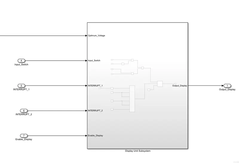
Subsystem consists of
The model is simulated and there are no errors.
Now check the Model advisor and the report is as follows:
file:///D:/Matlab%20Works/slprj/modeladvisor/traffic_jam_assist/report_203.html
For the model the Code generation is completed and it is as:
traffic_jam_assist.c file code is as:
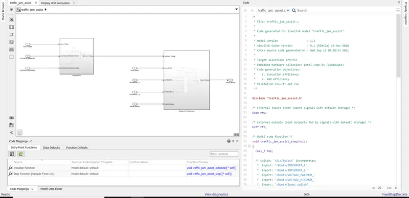
.c code is:
/*
 * File: traffic_jam_assist.c
 *
 * Code generated for Simulink model 'traffic_jam_assist'.
 *
 * Model version                  : 1.3
 * Simulink Coder version         : 9.1 (R2019a) 23-Nov-2018
 * C/C++ source code generated on : Wed Sep 15 00:28:53 2021
 *
 * Target selection: ert.tlc
 * Embedded hardware selection: Intel->x86-64 (Windows64)
 * Code generation objectives:
 *    1. Execution efficiency
 *    2. RAM efficiency
 * Validation result: Not run
 */

#include "traffic_jam_assist.h"

/* External inputs (root inport signals with default storage) */
ExtU rtU;

/* External outputs (root outports fed by signals with default storage) */
ExtY rtY;

/* Model step function */
void traffic_jam_assist_step(void)
{
  real_T tmp;

  /* Switch: '<S1>/Switch' incorporates:
   *  Inport: '<Root>/INTERRUPT_1'
   *  Inport: '<Root>/INTERRUPT_2 '
   *  Inport: '<Root>/VOLTAGE_MAXIMUM_'
   *  Inport: '<Root>/VOLTAGE_MINIMUM_'
   *  Inport: '<Root>/input_switch'
   *  Inport: '<Root>/input_voltage'
   *  Logic: '<S1>/Logical Operator'
   *  Logic: '<S1>/Logical Operator1'
   *  Logic: '<S1>/Logical Operator2'
   *  Logic: '<S2>/AND'
   *  RelationalOperator: '<S1>/Relational Operator1'
   *  RelationalOperator: '<S2>/Greater_than_equal_to'
   *  RelationalOperator: '<S2>/Less_than_equal_to'
   */
  if ((rtU.input_voltage >= rtU.VOLTAGE_MINIMUM_) && (rtU.input_voltage <=
       rtU.VOLTAGE_MAXIMUM_) && (!(rtU.input_switch != 0.0)) && (rtU.INTERRUPT_1
       == rtU.INTERRUPT_2)) {
    /* Saturate: '<S1>/Saturation' incorporates:
     *  Inport: '<Root>/enable_display'
     */
    if (rtU.enable_display > 0.5) {
      tmp = 0.5;
    } else if (rtU.enable_display < -0.5) {
      tmp = -0.5;
    } else {
      tmp = rtU.enable_display;
    }

    /* End of Saturate: '<S1>/Saturation' */

    /* MultiPortSwitch: '<S1>/Multiport Switch' */
    if ((int32_T)tmp == 1) {
      /* Outport: '<Root>/output_display' incorporates:
       *  Constant: '<S1>/ON_MODE'
       */
      rtY.output_display = 1.0;
    } else {
      /* Outport: '<Root>/output_display' incorporates:
       *  Constant: '<S1>/STANDBY_MODE'
       */
      rtY.output_display = 3.0;
    }

    /* End of MultiPortSwitch: '<S1>/Multiport Switch' */
  } else {
    /* Outport: '<Root>/output_display' incorporates:
     *  Constant: '<S1>/NO_DISPLAY'
     */
    rtY.output_display = 0.0;
  }

  /* End of Switch: '<S1>/Switch' */
}

/* Model initialize function */
void traffic_jam_assist_initialize(void)
{
  /* (no initialization code required) */
}

/*
 * File trailer for generated code.
 *
 * [EOF]
 */
traffic_jam_assist.h file code is:
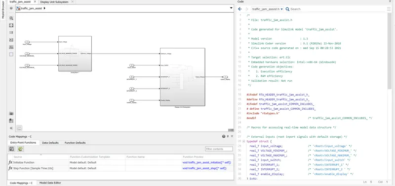
.h code is :
/*
 * File: traffic_jam_assist.h
 *
 * Code generated for Simulink model 'traffic_jam_assist'.
 *
 * Model version                  : 1.3
 * Simulink Coder version         : 9.1 (R2019a) 23-Nov-2018
 * C/C++ source code generated on : Wed Sep 15 00:28:53 2021
 *
 * Target selection: ert.tlc
 * Embedded hardware selection: Intel->x86-64 (Windows64)
 * Code generation objectives:
 *    1. Execution efficiency
 *    2. RAM efficiency
 * Validation result: Not run
 */

#ifndef RTW_HEADER_traffic_jam_assist_h_
#define RTW_HEADER_traffic_jam_assist_h_
#ifndef traffic_jam_assist_COMMON_INCLUDES_
# define traffic_jam_assist_COMMON_INCLUDES_
#include "rtwtypes.h"
#endif                                 /* traffic_jam_assist_COMMON_INCLUDES_ */

/* Macros for accessing real-time model data structure */

/* External inputs (root inport signals with default storage) */
typedef struct {
  real_T input_voltage;                /* '<Root>/input_voltage' */
  real_T VOLTAGE_MINIMUM_;             /* '<Root>/VOLTAGE_MINIMUM_' */
  real_T VOLTAGE_MAXIMUM_;             /* '<Root>/VOLTAGE_MAXIMUM_' */
  real_T input_switch;                 /* '<Root>/input_switch' */
  real_T INTERRUPT_1;                  /* '<Root>/INTERRUPT_1' */
  real_T INTERRUPT_2;                  /* '<Root>/INTERRUPT_2 ' */
  real_T enable_display;               /* '<Root>/enable_display' */
} ExtU;

/* External outputs (root outports fed by signals with default storage) */
typedef struct {
  real_T output_display;               /* '<Root>/output_display' */
} ExtY;

/* External inputs (root inport signals with default storage) */
extern ExtU rtU;

/* External outputs (root outports fed by signals with default storage) */
extern ExtY rtY;

/* Model entry point functions */
extern void traffic_jam_assist_initialize(void);
extern void traffic_jam_assist_step(void);

/*-
 * The generated code includes comments that allow you to trace directly
 * back to the appropriate location in the model.  The basic format
 * is <system>/block_name, where system is the system number (uniquely
 * assigned by Simulink) and block_name is the name of the block.
 *
 * Use the MATLAB hilite_system command to trace the generated code back
 * to the model.  For example,
 *
 * hilite_system('<S3>')    - opens system 3
 * hilite_system('<S3>/Kp') - opens and selects block Kp which resides in S3
 *
 * Here is the system hierarchy for this model
 *
 * '<Root>' : 'traffic_jam_assist'
 * '<S1>'   : 'traffic_jam_assist/Display Unit Subsystem'
 * '<S2>'   : 'traffic_jam_assist/Subsystem 1'
 */
#endif                                 /* RTW_HEADER_traffic_jam_assist_h_ */

/*
 * File trailer for generated code.
 *
 * [EOF]
 */
The main file - ert_main.c code is :
/*
 * File: ert_main.c
 *
 * Code generated for Simulink model 'traffic_jam_assist'.
 *
 * Model version                  : 1.3
 * Simulink Coder version         : 9.1 (R2019a) 23-Nov-2018
 * C/C++ source code generated on : Wed Sep 15 00:28:53 2021
 *
 * Target selection: ert.tlc
 * Embedded hardware selection: Intel->x86-64 (Windows64)
 * Code generation objectives:
 *    1. Execution efficiency
 *    2. RAM efficiency
 * Validation result: Not run
 */

#include <stddef.h>
#include <stdio.h>              /* This ert_main.c example uses printf/fflush */
#include "traffic_jam_assist.h"        /* Model's header file */
#include "rtwtypes.h"

/*
 * Associating rt_OneStep with a real-time clock or interrupt service routine
 * is what makes the generated code "real-time".  The function rt_OneStep is
 * always associated with the base rate of the model.  Subrates are managed
 * by the base rate from inside the generated code.  Enabling/disabling
 * interrupts and floating point context switches are target specific.  This
 * example code indicates where these should take place relative to executing
 * the generated code step function.  Overrun behavior should be tailored to
 * your application needs.  This example simply sets an error status in the
 * real-time model and returns from rt_OneStep.
 */
void rt_OneStep(void);
void rt_OneStep(void)
{
  static boolean_T OverrunFlag = false;

  /* Disable interrupts here */

  /* Check for overrun */
  if (OverrunFlag) {
    return;
  }

  OverrunFlag = true;

  /* Save FPU context here (if necessary) */
  /* Re-enable timer or interrupt here */
  /* Set model inputs here */

  /* Step the model */
  traffic_jam_assist_step();

  /* Get model outputs here */

  /* Indicate task complete */
  OverrunFlag = false;

  /* Disable interrupts here */
  /* Restore FPU context here (if necessary) */
  /* Enable interrupts here */
}

/*
 * The example "main" function illustrates what is required by your
 * application code to initialize, execute, and terminate the generated code.
 * Attaching rt_OneStep to a real-time clock is target specific.  This example
 * illustrates how you do this relative to initializing the model.
 */
int_T main(int_T argc, const char *argv[])
{
  /* Unused arguments */
  (void)(argc);
  (void)(argv);

  /* Initialize model */
  traffic_jam_assist_initialize();

  /* Attach rt_OneStep to a timer or interrupt service routine with
   * period 10.0 seconds (the model's base sample time) here.  The
   * call syntax for rt_OneStep is
   *
   *  rt_OneStep();
   */
  printf("Warning: The simulation will run forever. "
         "Generated ERT main won't simulate model step behavior. "
         "To change this behavior select the 'MAT-file logging' option.\n");
  fflush((NULL));
  while (1) {
    /*  Perform other application tasks here */
  }

  /* The option 'Remove error status field in real-time model data structure'
   * is selected, therefore the following code does not need to execute.
   */
#if 0

  /* Disable rt_OneStep() here */
#endif

  return 0;
}

/*
 * File trailer for generated code.
 *
 * [EOF]
 */
Thus code is generated for the model. The model is attached for the reference.
CONCLUSION: An algorithm is created for TRAFFIC JAM ASSISTANT and separate Data Dictionary is also created for the model.