Vehicle Direction Detection
Aim: To create a Simulink Data Dictionary file and a Simulink model for Vehicle Direction Detection.
Overview:
Identifying the direction of the vehicle is one of the important & diverse features in Autonomous driving & Advanced Driver Assistance Features. This particular sub-feature of identifying the direction of the vehicle is basically identifying the direction the vehicle is taking based on the camera input.
The camera reads the road signs & stores them into its memory with unique values for a left turn, right turn & straight drive. Depending on the direction it is taking, the final indication is given to the driver – as an indication if he is driving in the recommended direction or not.
Vehicle Direction Determination can also be coupled alongside features like GPS systems to identify whether the vehicle is reaching its destination in an optimized manner. This sub-feature can also be used along with Lane Detection, Highway Warning, Ramp Entry / Exit in Wrong Way Detection, etc.
Objective:
- Development of MATLAB Simulink model as per requirement.
- Tag the requirements to the Simulink model
- MBD compliant changes, Data Dictionary creation & code generation
Requirements:
Requirement - 1:
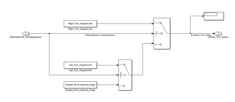
- Steering wheel input as yaw rate (Signal name: SteeringWheel_YawDegreeInput) is the input for this system.
- This is compared against 3 angular values, one each for a left turn, right turn & straight drive (Calibration Values: Right_Turn_AngularLimit, Left_Turn_AngularLimit, Straight_Drive_Steering_Angle) to say which specific direction the steering wheel is turning towards.
- Use switch blocks to compare & develop this requirement. Keep this requirement in a subsystem & the output of this requirement is a local signal (Signal Name: Vehicle_Turn_Status).
Requirement – 2:
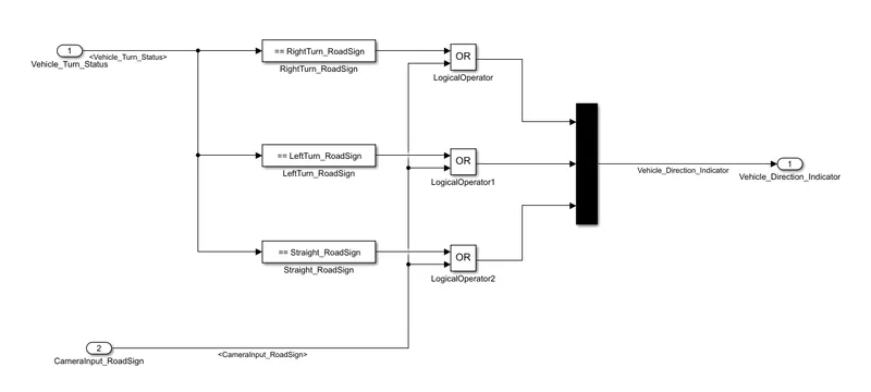
- Keep this requirement as a separate subsystem. Inputs to this requirement are a local signal from requirement 1 (Signal Name: Vehicle_Turn_Status) & an input signal from the camera (Signal Name: CameraInput_RoadSign), which confirms the occurrence of a road sign.
- Signal Vehicle_Turn_Status is compared against calibration values (Calibration Values: RightTurn_RoadSign, LeftTurn_RoadSign, Straight_RoadSign), if each of them is found equal, then each of the three corresponding output is compared against the camera input signal,
- Using a logical operator block, only one among them is finally given as output signal (Signal Name: Vehicle_Direction_Indicator).
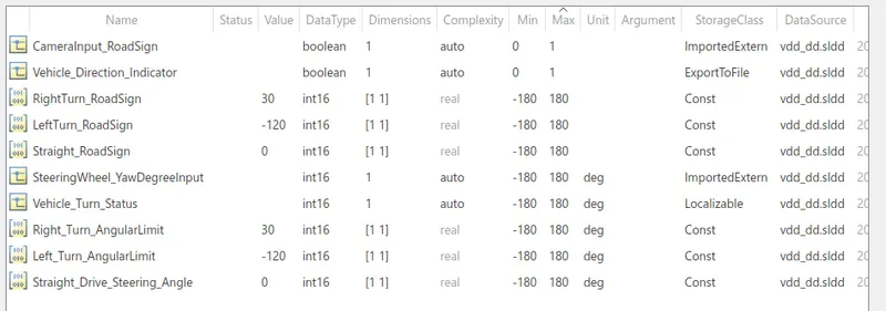
Signals & Calibration Data List:
|
Signal / Calibration Name |
Signal Type |
Data Type |
Dimension |
Min |
Max |
Initial Value |
Units |
|
SteeringWheel_YawDegreeInput |
Input |
Int16 |
1 |
-180 |
180 |
- |
Deg |
|
CameraInput_RoadSign |
Input |
Boolean |
1 |
0 |
1 |
- |
- |
|
Vehicle_Turn_Status |
Local |
Int16 |
1 |
-180 |
180 |
- |
Deg |
|
Right_Turn_AngularLimit |
Calibration |
Int16 |
[1 1] |
-180 |
180 |
30 |
Deg |
|
Left_Turn_AngularLimit |
Calibration |
Int16 |
[1 1] |
-180 |
180 |
-120 |
Deg |
|
Straight_Drive_Steering_Angle |
Calibration |
Int16 |
[1 1] |
-180 |
180 |
0 |
Deg |
|
RightTurn_RoadSign |
Calibration |
Int16 |
[1 1] |
-180 |
180 |
30 |
|
|
LeftTurn_RoadSign |
Calibration |
Int16 |
[1 1] |
-180 |
180 |
-120 |
|
|
Straight_RoadSign |
Calibration |
Int16 |
[1 1] |
-180 |
180 |
0 |
|
|
Vehicle_Direction_Indicator |
Output |
Boolean |
1 |
0 |
1 |
- |
- |
Procedure:
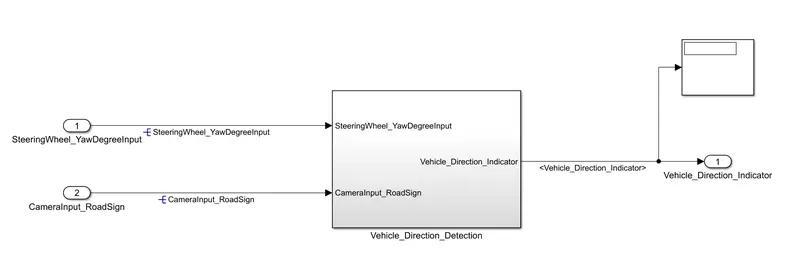
The following figure shows the Simulink model created for the Vehicle direction detection application
Subsystem:
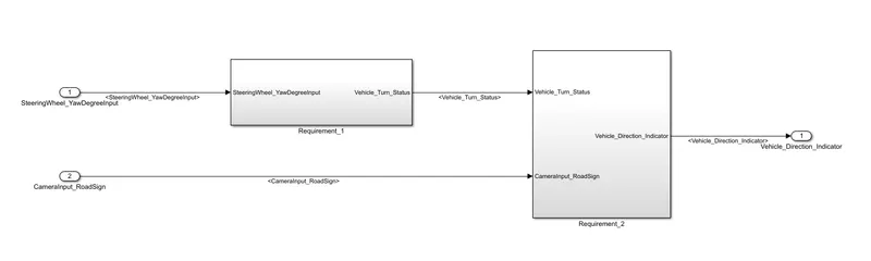
Design according to the 1st requirement:
Design according to the 2nd requirement:
SLDD file:
Results:
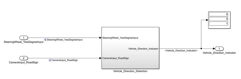
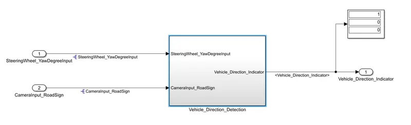
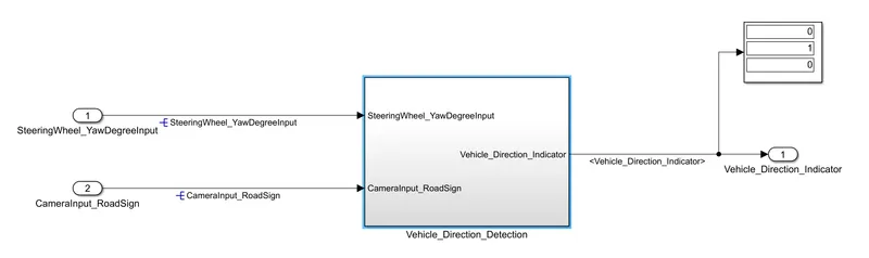
After simulating the above model using input from the sldd file, we get the following outputs
For Straight turn:
For Right turn:
For Left turn:
Now generating the code for the above model using Embedded C coder.
Code generation:
/*
 * File: vdd_model.c
 *
 * Code generated for Simulink model 'vdd_model'.
 *
 * Model version                  : 1.2
 * Simulink Coder version         : 9.5 (R2021a) 14-Nov-2020
 * C/C++ source code generated on : Fri Jul  2 20:23:18 2021
 *
 * Target selection: ert.tlc
 * Embedded hardware selection: Intel->x86-64 (Windows64)
 * Code generation objectives: Unspecified
 * Validation result: Not run
 */

#include "vdd_model.h"
#include "vdd_model_private.h"

/* Exported data definition */

/* Const memory section */
/* Definition for custom storage class: Const */
const int16_T LeftTurn_RoadSign = -120;/* Referenced by: '/Constant' */
const int16_T Left_Turn_AngularLimit = -120;
                              /* Referenced by: '/Left_Turn_AngularLimit' */
const int16_T RightTurn_RoadSign = 30; /* Referenced by: '/Constant' */
const int16_T Right_Turn_AngularLimit = 30;
                             /* Referenced by: '/Right_Turn_AngularLimit' */
const int16_T Straight_Drive_Steering_Angle = 0;
                       /* Referenced by: '/Straight_Drive_Steering_Angle' */
const int16_T Straight_RoadSign = 0;   /* Referenced by: '/Constant' */

/* External outputs (root outports fed by signals with default storage) */
ExtY_vdd_model_T vdd_model_Y;

/* Real-time model */
static RT_MODEL_vdd_model_T vdd_model_M_;
RT_MODEL_vdd_model_T *const vdd_model_M = &vdd_model_M_;

/* Model step function */
void vdd_model_step(void)
{
  /* local block i/o variables */
  int16_T Vehicle_Turn_Status;

  /* Outputs for Atomic SubSystem: '/Vehicle_Direction_Detection' */
  /* Switch: '/Switch' incorporates:
   *  Inport: '/SteeringWheel_YawDegreeInput'
   *  Switch: '/Switch1'
   */
  if (SteeringWheel_YawDegreeInput >= 30) {
    /* Switch: '/Switch' incorporates:
     *  Constant: '/Right_Turn_AngularLimit'
     */
    Vehicle_Turn_Status = Right_Turn_AngularLimit;
  } else if (SteeringWheel_YawDegreeInput != 0) {
    /* Switch: '/Switch1' incorporates:
     *  Constant: '/Left_Turn_AngularLimit'
     *  Switch: '/Switch'
     */
    Vehicle_Turn_Status = Left_Turn_AngularLimit;
  } else {
    /* Switch: '/Switch' incorporates:
     *  Constant: '/Straight_Drive_Steering_Angle'
     *  Switch: '/Switch1'
     */
    Vehicle_Turn_Status = Straight_Drive_Steering_Angle;
  }

  /* End of Switch: '/Switch' */

  /* Outport: '/Vehicle_Direction_Indicator' incorporates:
   *  Constant: '/Constant'
   *  Constant: '/Constant'
   *  Constant: '/Constant'
   *  Inport: '/CameraInput_RoadSign'
   *  Logic: '/LogicalOperator'
   *  Logic: '/LogicalOperator1'
   *  Logic: '/LogicalOperator2'
   *  RelationalOperator: '/Compare'
   *  RelationalOperator: '/Compare'
   *  RelationalOperator: '/Compare'
   */
  vdd_model_Y.Vehicle_Direction_Indicator[0] = ((Vehicle_Turn_Status ==
    RightTurn_RoadSign) || CameraInput_RoadSign);
  vdd_model_Y.Vehicle_Direction_Indicator[1] = ((Vehicle_Turn_Status ==
    LeftTurn_RoadSign) || CameraInput_RoadSign);
  vdd_model_Y.Vehicle_Direction_Indicator[2] = ((Vehicle_Turn_Status ==
    Straight_RoadSign) || CameraInput_RoadSign);

  /* End of Outputs for SubSystem: '/Vehicle_Direction_Detection' */
}

/* Model initialize function */
void vdd_model_initialize(void)
{
  /* (no initialization code required) */
}

/* Model terminate function */
void vdd_model_terminate(void)
{
  /* (no terminate code required) */
}

/*
 * File trailer for generated code.
 *
 * [EOF]
 */
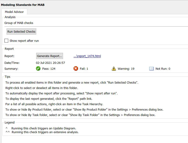
Model Advisor check:
Conclusion: Thus, a Simulink model for Vehicle Direction Detection has been designed and a Simulink Data Dictionary file has been created along with the code generation of the created model and its model advisor report satisfactorily.