Fuel cell powered vehicle model
Make a MATLAB model of fuel cell-powered electric vehicle and comment on results
What is a Fuel Cell?
A fuel cell is an electrochemical cell that converts the chemical energy of a fuel (often hydrogen) and an oxidizing agent (often oxygen) into electricity through a pair of redox reactions.[2] Fuel cells are different from most batteries in requiring a continuous source of fuel and oxygen (usually from air) to sustain the chemical reaction, whereas in a battery the chemical energy usually comes from metals and their ions or oxides that are commonly already present in the battery, except in flow batteries. Fuel cells can produce electricity continuously for as long as fuel and oxygen are supplied.
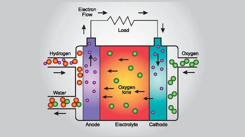
Fuel Cell-powered electric vehicle
Fuel cell electric vehicles (FCEVs) are powered by hydrogen. They are more efficient than conventional internal combustion engine vehicles and produce no tailpipe emissions—they only emit water vapor and warm air. FCEVs and the hydrogen infrastructure to fuel them are in the early stages of implementation.
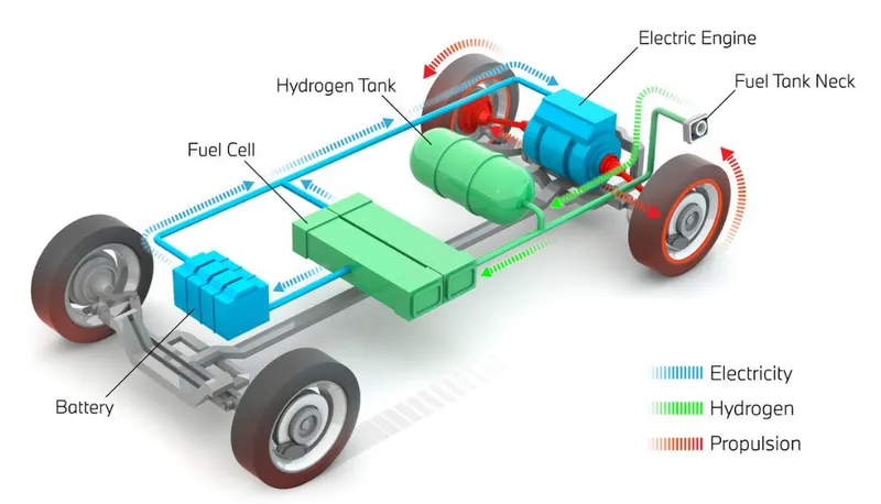
FCEVs use a propulsion system similar to that of electric vehicles, where energy stored as hydrogen is converted to electricity by the fuel cell. Unlike conventional internal combustion engine vehicles, these vehicles produce no harmful tailpipe emissions. FCEVs are fueled with pure hydrogen gas stored in a tank on the vehicle. Similar to conventional internal combustion engine vehicles, they can fuel in less than 4 minutes and have a driving range of over 300 miles. FCEVs are equipped with other advanced technologies to increase efficiency, such as regenerative braking systems, which capture the energy lost during braking and store it in a battery. Major automobile manufacturers are offering a limited but growing number of production FCEVs to the public in certain markets, in sync with what the developing infrastructure can support.
How do Fuel Cells work?
The most common type of fuel cell for vehicle applications is the polymer electrolyte membrane (PEM) fuel cell. In a PEM fuel cell, an electrolyte membrane is sandwiched between a positive electrode (cathode) and a negative electrode (anode). Hydrogen is introduced to the anode, and oxygen (from air) is introduced to the cathode. The hydrogen molecules break apart into protons and electrons due to an electrochemical reaction in the fuel cell catalyst. Protons then travel through the membrane to the cathode.
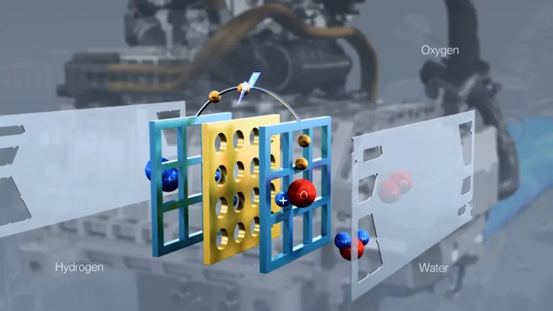
The electrons are forced to travel through an external circuit to perform work (providing power to the electric car) then recombine with the protons on the cathode side, where the protons, electrons, and oxygen molecules combine to form water.
The following figure shows the Simulink model for the Proton Exchange Membrane (PEM) Fuel Cell Stack model feeding an average value of 100 V DC/DC converter
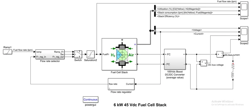
The nominal Fuel Cell Stack voltage is 45V dc and the nominal power is 6kW. The converter is loaded by an RL element of 6kW with a time constant of 1 sec. During the first 10 secs, the utilization of the hydrogen is constant to the nominal value (Uf_H2 = 99.56%) using a fuel flow rate regulator. After 10 secs, the flow rate regulator is bypassed and the rate of fuel is increased to the maximum value of 85 lpm in order to observe the variation in the stack voltage. That will affect the stack efficiency, fuel consumption, and air consumption.
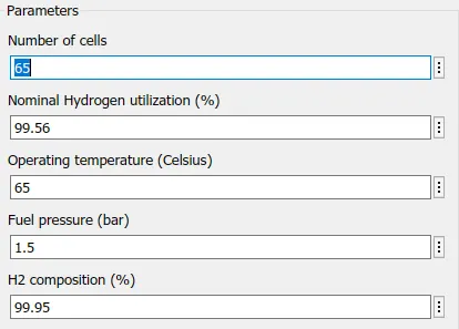
The parameters of the flow rate regulator block are as shown below
The following figure shows the subsystem of the flow rate selector
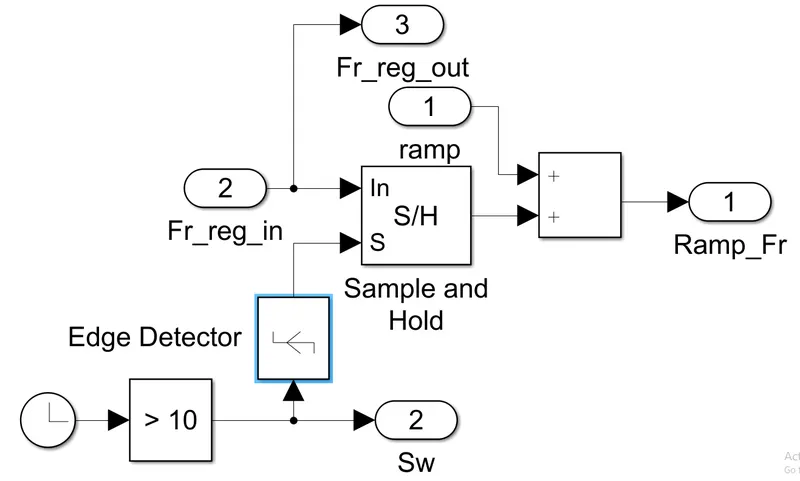
The main block used here is the Sample and Hold circuit to sample the input analog signal and hold the sampled signal.
The following figure shows the subsystem of a DC-DC converter
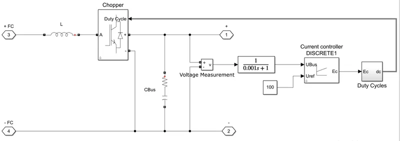
Here, an average value Boost converter, a PI controller with 0.0005 proportional gain and 0.15 integral gain, and a duty cycle of 0.5*(u[1]+1).
To initialize the simulation, all the parameters are kept at default and a 6W 45V dc PEM Fuel cell stack with detailed parameters is used.
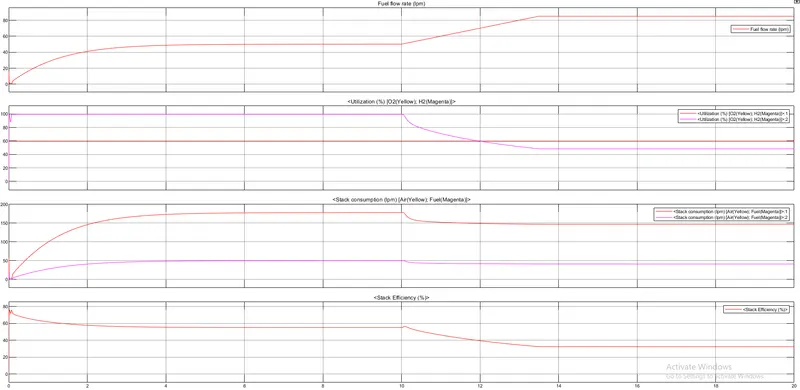
After running the model for the simulation time of 20 secs, we get the following results for the Fuel flow rate, Hydrogen and oxygen utilization, fuel and air consumption, and efficiency
and, Fuel cell voltage, current, DC/DC converter voltage, and DC/DC converter current signals
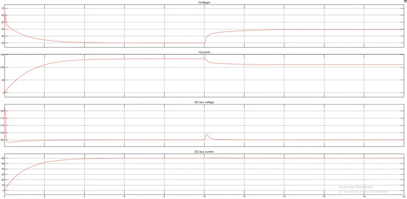
At t = 0 s, the DC/DC converter applies 100Vdc to the RL load (the initial current of the load is 0A). The fuel utilization is set to the nominal value of 99.56%. The current increases to the value of 133A. The flow rate is automatically set in order to maintain the nominal fuel utilization. The peak voltage of 122Vdc at the beginning of the simulation is caused by the transient state of the voltage regulator.
At t = 10 s, the fuel flow rate is increased from 50 liters per minute (lpm) to 85 lpm during 3.5 s reducing by doing so the hydrogen utilization. This causes an increase of the Nernst voltage so the fuel cell current will decrease. Therefore the stack consumption and the efficiency will decrease. The fuel cell voltage will also rise up and attains 55V in 3 secs and the fuel cell current will drop down to 110A.
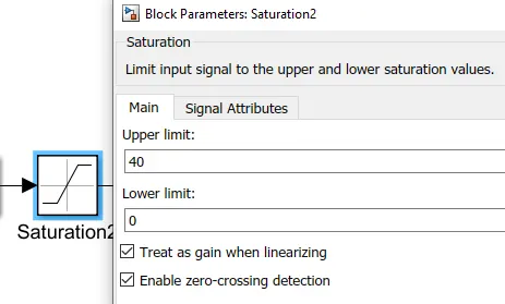
Now, changing the saturation parameter to 40
and Fuel Cell stack model detail to Simplified
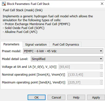
By doing this, we are cutting off the fuel flow rate to the Fuel Cell stack block.
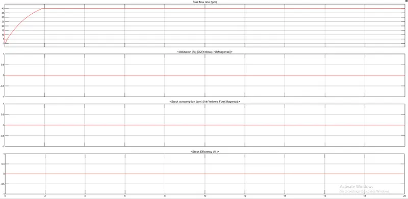
Now, running the simulation for these changed parameters, we get the following results for the Fuel flow rate, Hydrogen and oxygen utilization, fuel and air consumption, and efficiency
and, Fuel cell voltage, current, DC/DC converter voltage, and DC/DC converter current signals
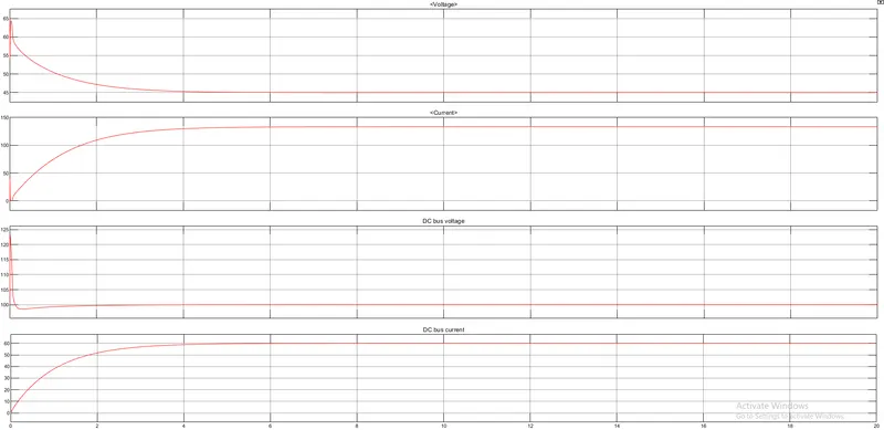
At t= 0 secs, the fuel utilization, stack consumption, and stack efficiency all are at 0 and do not show any response since the fuel flow rate has been cut off. The peak voltage of 122Vdc of the DC-DC converter at the beginning of the simulation is caused by the transient state of the voltage regulator.
The flow rate is automatically set in order to maintain the nominal fuel utilization and rise to 40 lpm in 1.8 secs and remains constant throughout.