Design of an Electric Rickshaw using Simulink
Aim: To create a MATLAB model of an Electric Rickshaw using a Lithium-ion Battery, Permanent Magnet Brushed type DC motor, a motor Controller, and various Powertrain block sets.
Procedure:
This includes the engine, transmission, the driveshaft, differentials, axles; basically anything from the engine through to the rotating wheels.
Initialization of the Electric Rickshaw model
1. Vehicle Dynamics:
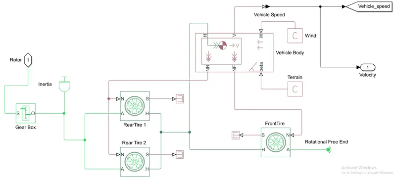
The following figure shows the subsystem of the Vehicle Dynamics used for the model
The following blocks are used for the implementation of this subsystem
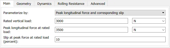
a. Tire (Magic formula): It represents the longitudinal behavior of a highway tire. 3 tires are used in total, 1 for the front wheel, and 2 for rear wheels. The rear wheels are used for the tractive power action. There are 4 terminals in this block namely 'H' (hub), 'S' (tire slip), 'N' (normal force applied to the tire), and 'A' (axle connection).
b. Vehicle body: It represents a two-axle vehicle body in longitudinal motion. The block accounts for body mass, aerodynamic drag, road incline, and weight distribution between axles due to acceleration and road profile. There are 6 terminals in this block namely 'H' (horizontal motion), 'V' (longitudinal velocity), 'W' (headwind speed), 'NR' (rear axle normal force), 'NF' (front axle normal force), and 'beta' (road incline angle).
c. Gear Box: It represents an ideal, non-planetary, fixed gear ratio gearbox. The gearbox is characterized by its only parameter, the Gear ratio, which can be positive or negative. There are 2 terminals in this block namely 'S' (input shaft) and 'O' (output shaft).
d. Inertia: It represents an ideal mechanical translational inertia.
Connections made:
- Flip the front tire and connect the 'H' terminal of the front wheel to the 'H' terminal of the vehicle body.
- Short the 'N' terminals of both the rear wheels and connect them to the 'NR' terminal of the vehicle body.
- Connect the 'N' terminal of the front wheel to the 'NF' terminal of the vehicle body.
- Short the 'A' terminals of both the rear wheels and connect them to the 'O' terminal of the Gearbox.
- Terminate the 'A' terminal of the front wheel with the help of a Rotational Free End block.
- Terminate the 'S' terminal of all the three wheels with the help of a PS-Terminal block.
- Connect PS-constants to both 'W' and 'beta' terminals of the vehicle body.
- The input to this subsystem is connected to the 'S' terminal of the Gearbox.
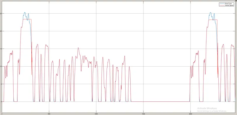
- The output of this subsystem is given through the 'V' terminal of the vehicle body where one path is connected to a 'Vehicle_speed' Goto block and the From block is connected to a scope showing the velocity of the vehicle over the defined period of time and another path is connected to an output port.
- The output port is further connected to an integrator block.
2. Electrical Network:
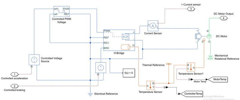
The following figure shows the subsystem of the Electrical network used in this model
The following blocks are used for the implementation of this subsystem
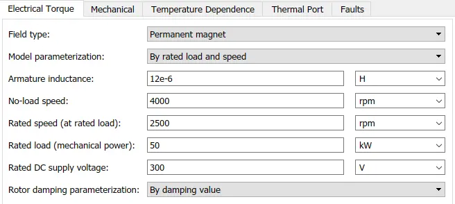
a. DC motor: A DC motor is any of a class of rotary electrical motors that converts direct current electrical energy into mechanical energy. This block represents the electrical and torque characteristics of a DC motor. It has both electrical and mechanical components and is coupled through a shaft. There are 5 terminals in this block namely '+ve' and '-ve' from the electrical part, 'R' (rotor casing) and 'C' (motor casing) from the mechanical part, and 'H' (thermal port) for the thermal measurements.
b. H-bridge: H-bridge is an electronic circuit that switches the polarity of a voltage applied to a load. These circuits are often used in robotics and other applications to allow DC motors to run forward or backward. This block represents an H-bridge motor drive. There are 7 terminals in this block namely '+ve' and '-ve' which are the output terminals, 'H' (thermal port) for the thermal measurements, 'PWM' (pulse-width modulated signal), 'REF' (reference), 'REV' (reverse), and 'BRK' (brake).
c. Controlled PWM voltage: Controlled pulse-width modulated voltage regulator works by driving the motor with a series of “ON-OFF” pulses and varying the duty cycle, the fraction of time that the output voltage is “ON” compared to when it is “OFF”, of the pulses while keeping the frequency constant. There are 4 terminal in this block namely 'ref+' (positive electrical reference voltage), 'ref-' (negative electrical reference voltage), 'PWM' (pulse-width modulated) signal, and 'REF' (floating zero reference voltage).
d. Controlled voltage source: It is an ideal voltage source that is powerful enough to maintain the specified voltage at its output regardless of the current passing through it. This block has one physical signal input port and two electrical conserving ports associated with its electrical terminals. Here, two such controlled voltage source blocks are used.
e. Current sensor: Current sensor is a device that converts current measured in any electrical branch into a physical signal proportional to the current. Terminals '+' and '–' are electrical conserving ports through which the sensor is inserted into the circuit. Terminal 'I' is a physical signal port that outputs the measurement result.
f. Temperature sensor: The Temperature Sensor block represents an ideal temperature sensor, that is, a device that determines the temperature differential measured between two points without drawing any heat. Connections 'A' and 'B' are thermal conserving ports that connect to the two points where the temperature is being monitored. Port 'T' is a physical signal port that outputs the temperature differential value.
g. Electrical reference port, Mechanical rotational reference point, Thermal reference port, and the Solver configuration are the miscellaneous blocks used in this subsystem.
Connections made:
- There are two input ports to this subsystem and both are connected to the Controlled voltage source blocks respectively.
- The '+ve' of one of the controlled voltage sources is connected to the 'ref+' terminal of the controlled PWM voltage block and the '+ve' of the other is connected to the 'BRK' terminal of the H-bridge block.
- The 'PWM' terminal of the controlled PWM voltage block is connected to the 'PWM' port of the H-bridge block.
- Connect the '+' and '-' terminals of the H-bridge block to the DC motor terminals via the current sensor.
- The 'R' terminal of the DC motor is given to the output port of this subsystem.
- The 'H' terminal of the H-bridge and The DC Motor is connected to the 'A' terminals of each of the Temperature Sensor.
- The 'B' terminal of both the Temperature Sensors are connected to the Thermal reference port.
- All the reference terminals and '-' of the DC motor are connected to the Electrical reference port.
- The 'C' terminal of the DC motor is connected to the Mechanical reference point.
- And a Solver configuration is applied where all the reference nodes are grounded.
- The 'T' terminals of both the Temperature Sensors are connected to the 'Motortemp' Goto and 'Controllertemp' Goto blocks where the From blocks are connected to the scope showing the Motor and Controller temperatures respectively.
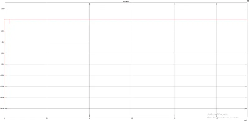
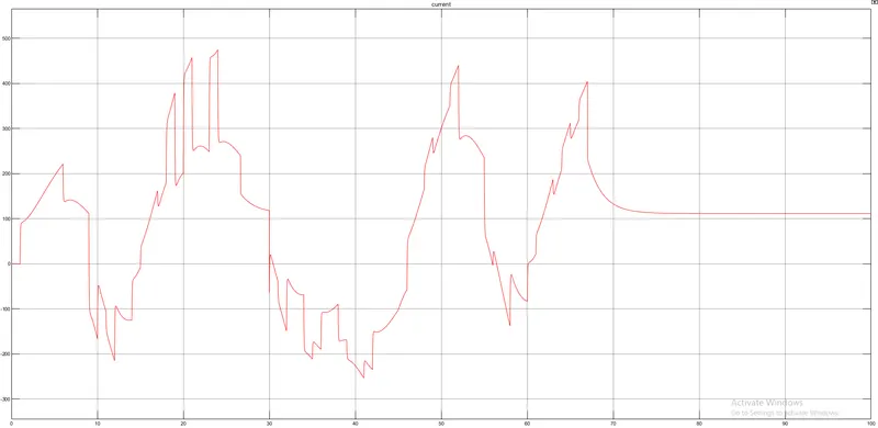
- There are two output ports in this subsystem, where the '+ Current sensor' output port is connected to the SOC and the Battery subsystems, and a scope showing the current flowing in the network, and the 'DC Motor output' port is connected to the Vehicle body subsystem.
3. Battery:
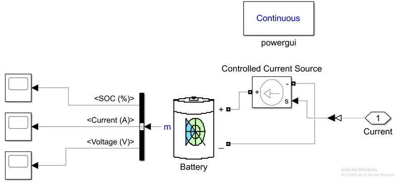
The following figure shows the subsystem of the Battery used in this model
The following blocks are used for the implementation of this subsystem
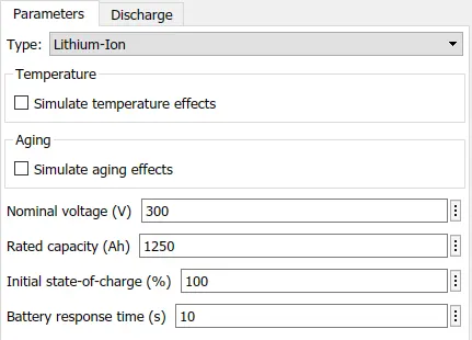
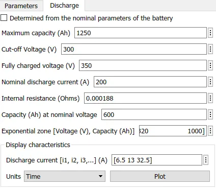
a. Battery: Battery is an electrical device used to give DC voltage across any 2 terminals. Here, a Lithium-ion type battery is used. There are 3 terminals in this block namely '+ve', '-ve', and 'm'.
b. Controlled current source: It is an ideal current source that is powerful enough to maintain the specified current through it regardless of the voltage across it. This block has one physical signal input port and two electrical conserving ports associated with its electrical terminals.
c. powergui: The powergui block allows you to choose one of these methods to solve your circuit:
-
Continuous, which uses a variable-step solver from Simulink
-
Discretization of the electrical system for a solution at fixed time steps
-
Continuous or discrete phasor solution
d. Bus selector: The Bus Selector block outputs the elements you select from the input bus. The block can output the selected elements separately or in a new virtual bus.
Connections made:
- There is one input to this system and it is connected to the signal input port of the Controlled current source with the help of a PS-Simulink converter.
- The '+' and '-' of the Battery are connected to the '+ and '-' of the Controlled current source respectively.
- The 'm' terminal of the battery is connected to the Bus selector.
- There are three outputs from the bus selector connected to the three scopes showing the SOC, Current, and Voltage of the battery respectively.
4. State-of-Charge (SOC):
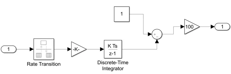
The following figure shows the subsystem to calculate the SOC given by the prepared Electric vehicle model
The following blocks are used for the implementation of this subsystem
a. Rate Transition: Rate Transition block transfers data from the output of a block operating at one rate to the input of another block operating at a different rate. The Rate Transition block's parameters allow you to specify options that trade data integrity and deterministic transfer for faster response and/or lower memory requirements.
b. Discrete-Time Integrator: The Discrete-Time Integrator block implements discrete-time integration or accumulation of the input signal. The block can integrate or accumulate using the Forward Euler, Backward Euler, and Trapezoidal methods.
c. Gain, Add/Subtract, and Constant are the miscellaneous blocks used in this subsystem.
Connections made:
- There is one input to this subsystem which is the current given by the Controlled current source and is connected to the Rate Transition block.
- The output of the Rate Transition block is given to the gain block and is further connected to the Discrete-Time Integrator block.
- The output of the Discrete-Time Integrator block and a Constant block is connected to the Add/Subtract block and the output of this is given to another gain block.
- The output of gain is given to the output port of this SOC subsystem.
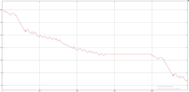
- The output port is connected to a scope showing the SOC of the battery after a successful run of the vehicle.
5. Drive Cycle Input:
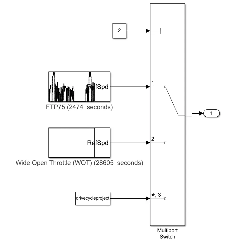
The following figure shows the Drive cycle subsystem used to give reference drive cycle input to this Electric Rickshaw model
The following blocks are used for the implementation of this subsystem
a. Drive Cycle Source (FTP75): Drive cycle source generates a standard or user-specified longitudinal drive cycle. This block output is the vehicle longitudinal speed. Here, an FTP75 drive cycle is used.
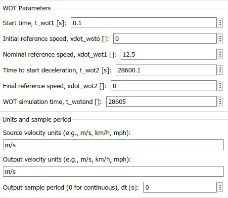
b. Drive Cycle Source (WOT): Drive cycle source generates a standard or user-specified longitudinal drive cycle. This block output is the vehicle longitudinal speed. Here, a Wide Open Throttle drive cycle is used.
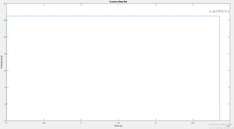
c. From Workspace: It is used to give the drive cycle data input to the model prepared manually in the excel spreadsheet and imported from the workspace.
d. Multiport switch: The Multiport Switch block determines which of several inputs to the block passes to the output. The block bases this decision on the value of the first input. The first input is the control input and the remaining inputs are the data inputs. The value of the control input determines which data input passes to the output.
e. Constant: It is given to the control input of the multiport switch and this value of the constant decides which data input passes to the output.
Connections made:
- Drive cycle source (FTP75), Drive cycle source (WOT), and From Workspace Excel sheet data are connected to the input ports of the Multiport switch.
- The Constant block is connected to the control input port of the Multiport switch.
- The output of this Multiport switch is the output port of this subsystem.
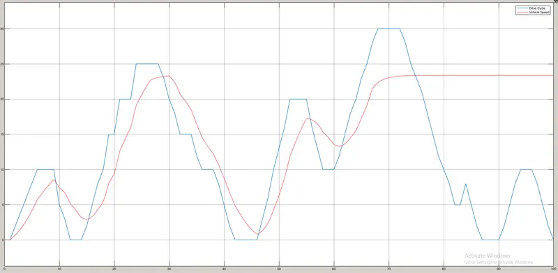
- The output port is given as input to the Controller subsystem and also to the scope showing the reference velocity set by the chosen drive cycle.
6. Controller:
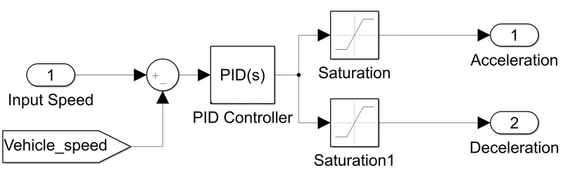
The following figure shows the Controller subsystem used for controlling the Motoring action
The following blocks are used for the implementation of this subsystem
a. PID Controller: The block is identical to the Discrete PID Controller block with the Time domain parameter set to continuous-time. The term PID stands for proportional integral derivative and it is one kind of device used to control different process variables like pressure, flow, temperature, and speed in industrial applications. In this controller, a control loop feedback device is used to regulate all the process variables.
b. Saturation: The Saturation block produces an output signal that is the value of the input signal bounded to the upper and lower saturation values. The upper and lower limits are specified by the parameters Upper limit and Lower limit.
c. Add/Subtract and Goto are the miscellaneous blocks used in this subsystem.
Connections made:
- There is one input to this subsystem which is the Input Reference Speed given by the Drive cycle subsystem and is connected to the Add/Subtract block.
- Another input to the Add/Subtract block is the feedback Vehicle speed from the Vehicle Dynamics subsystem.
- The output of the Add/Subtract block is given to the PID Controller.
- The Acceleration and Deceleration Controls from the PID Controller are taken as the output ports of this subsystem through the Saturation blocks.
Miscellaneous connections:
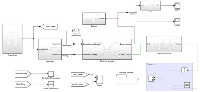
- The 'Velocity' output port of the Vehicle dynamics subsystem is connected to an integrator block.
- The output of the integrator block and a Constant block is given to the 'Multiply-Divide' block.
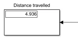
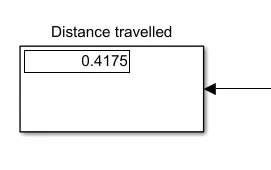
- The output of this 'Multiply-divide' block is then finally given to the Display block which shows the distance traveled by this model.
The following figure shows the main model design of an Electric Rickshaw designed
#Now, keeping the Multiport switch of the Drive Cycle Subsystem at '1' i-e using the FTP75 drive cycle.
Model parameters used for this Drive cycle are as follows
1. Vehicle dynamics subsystem:
a. Tire:

b. Vehicle Body:
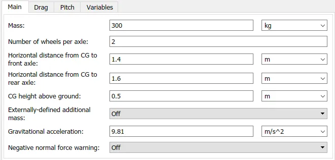
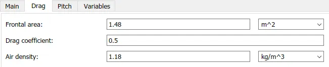
c. Gearbox:

2. Electrical Network subsystem:
a. DC Motor:
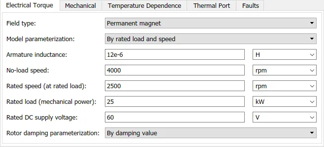
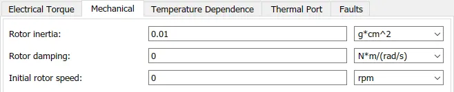


b. H-bridge:
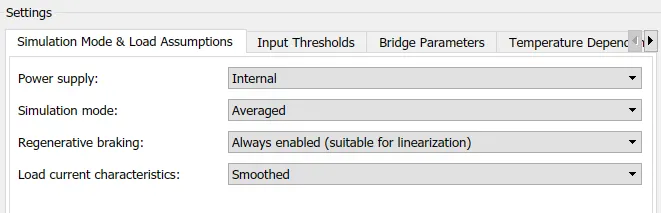

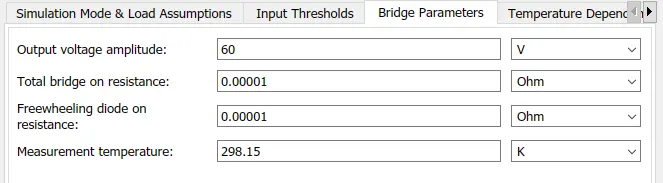
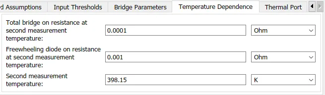

c. PWM Controlled Voltage:



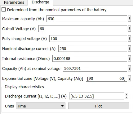
3. Battery subsystem:
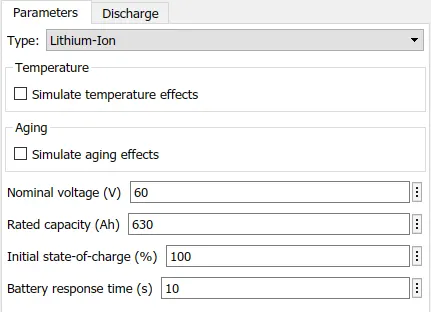
4. SOC subsystem:
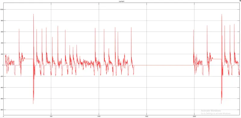
a. Current:
b. Gain input:

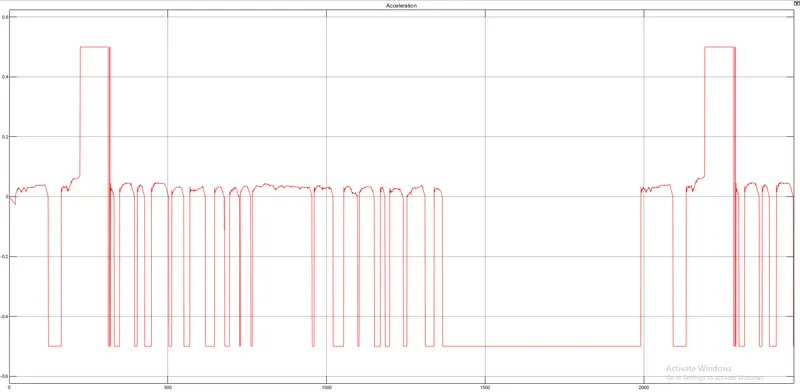
5. Controller (Throttle):
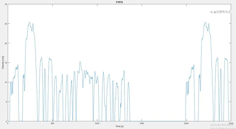
6. Drive cycle input:
Results:
a. Distance traveled:
b. Velocity:
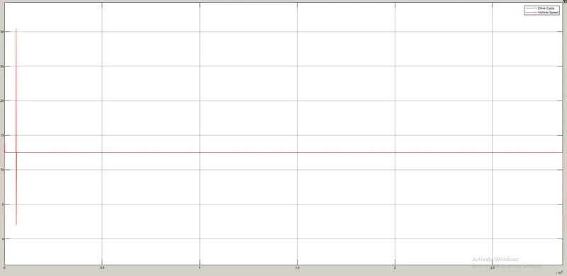
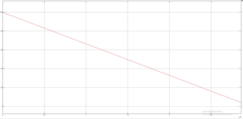
c. SOC:
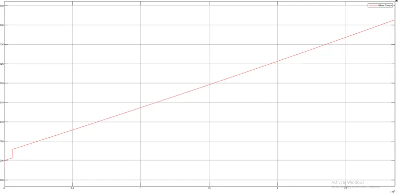
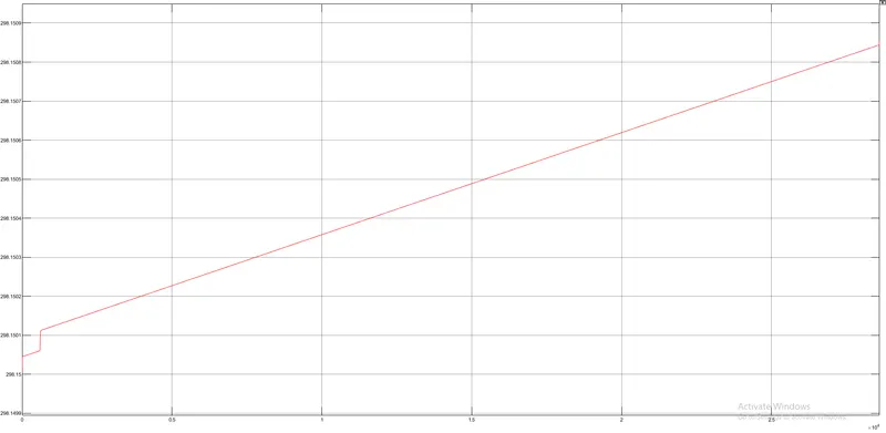
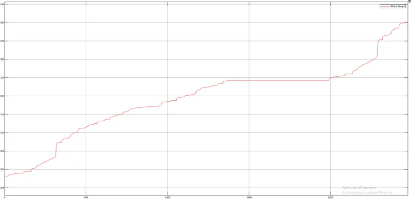
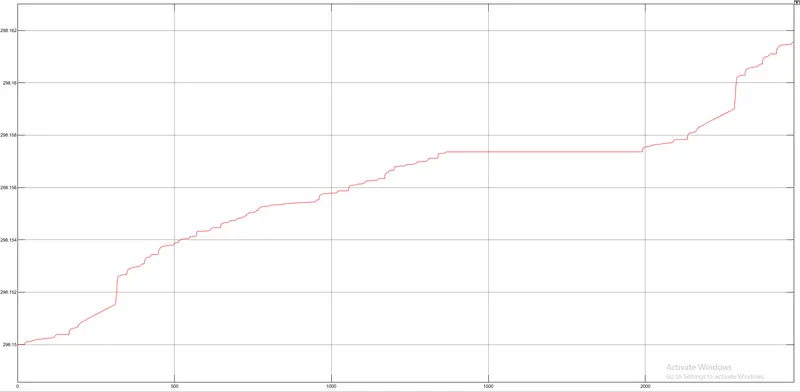
d. Motor and Controller temperature:
Case I:
For the Following PID gain values
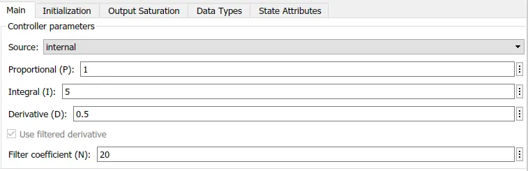
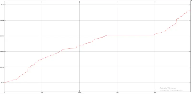
The motor and controller temperatures are as follows respectively
Case II:
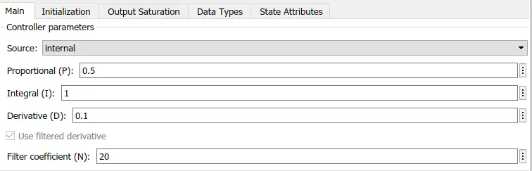
For the Following PID gain values
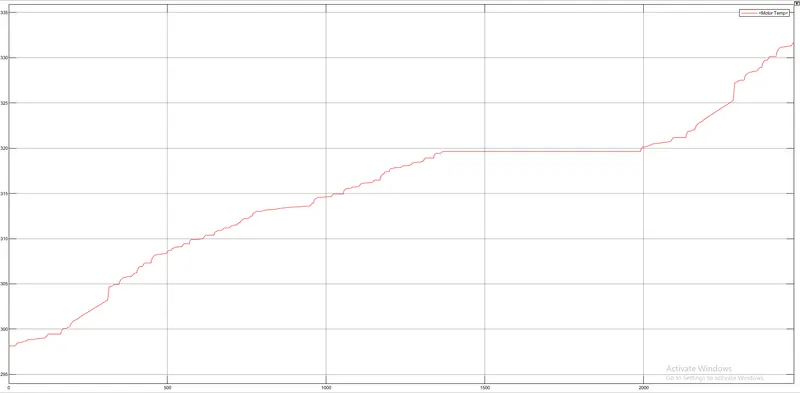
The motor and controller temperatures are as follows respectively
Case III:
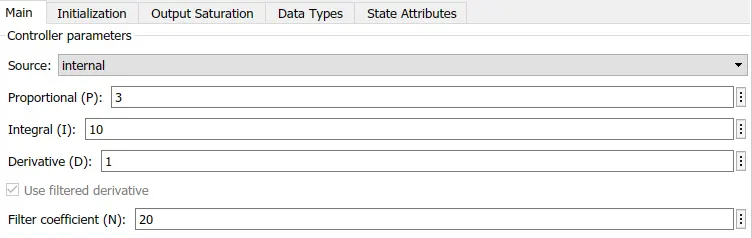
For the Following PID gain values
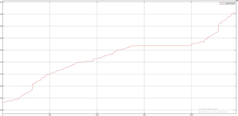
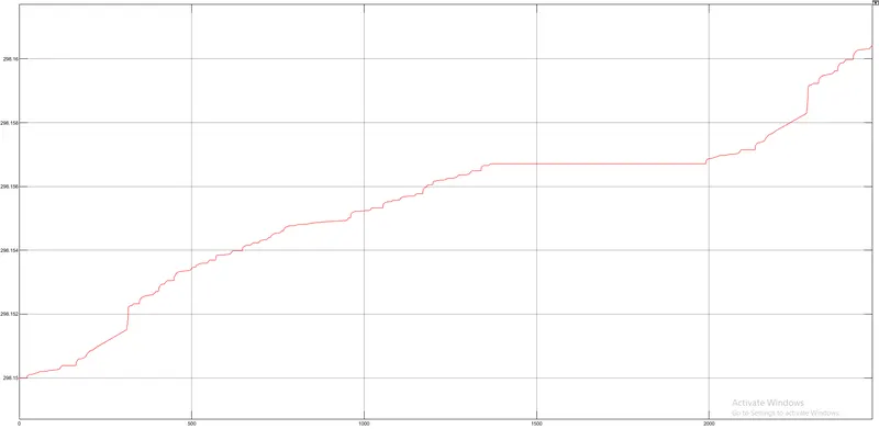
The motor and controller temperatures are as follows respectively
Conclusion:
| Case | Proportional gain | Integral gain | Derivative gain | Motor Temperature | Controller Temperature |
| I | 1 | 5 | 0.5 | `340.5^o K` | `298.1615^0 K` |
| II | 0.5 | 1 | 0.1 | `332^o K` | `298.159^o K` |
| III | 3 | 10 | 1 | `336^o K` | `298.1605^o K` |
- Open MATLAB and click on Import Data
- Open the saved excel spreadsheet in it
- In Output type, select Numeric Matrix
- Click on Import Selection
- Then the spreadsheet will get saved in the workspace
- To access this spreadsheet from the workspace, go to Simulink, then drive cycle subsystem and open the 'From workspace' block
- In it open the saved spreadsheet from the workspace
- Connect it to the Multiport switch
Results:
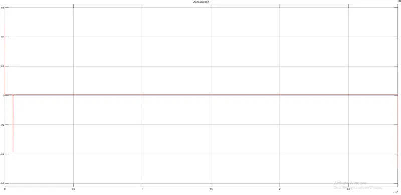
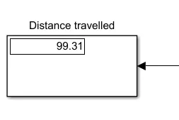
a. Distance Traveled:
b. Velocity:
c. SOC:
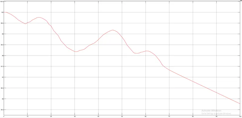
d. Motor and Controller temperatures according to the PID gain values
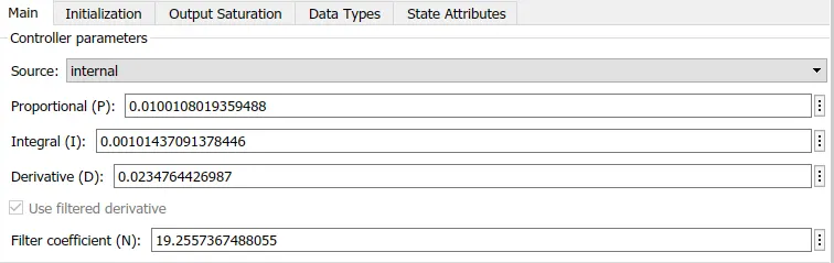
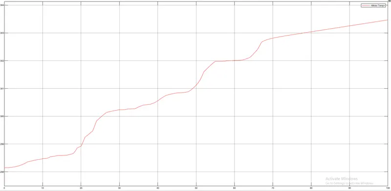
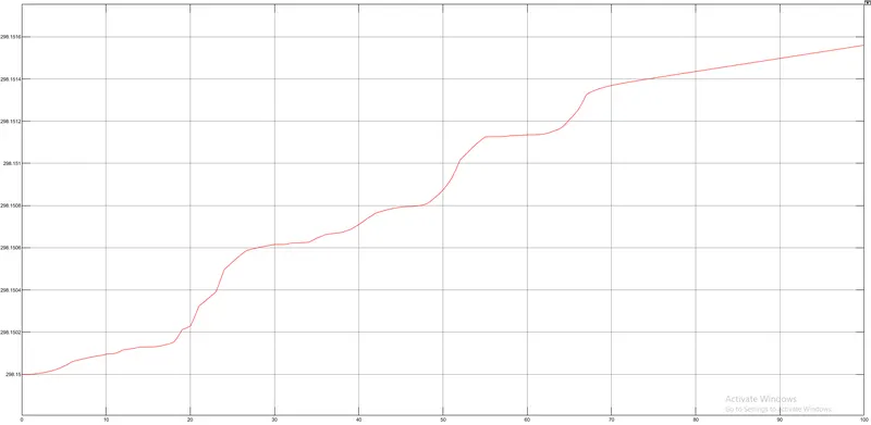
Conclusion: