Thermal modeling of a battery pack
Aim: To model and simulate 10 cells in a series lithium-ion battery pack, analyze the thermal effects and compare its life cycle performance at various temperatures, charge & discharge rates using MATLAB.
Theory
Lithium-ion battery
A lithium-ion battery or Li-ion battery is a type of rechargeable battery. Lithium-ion batteries are commonly used for portable electronics and electric vehicles and are growing in popularity for military and aerospace applications.
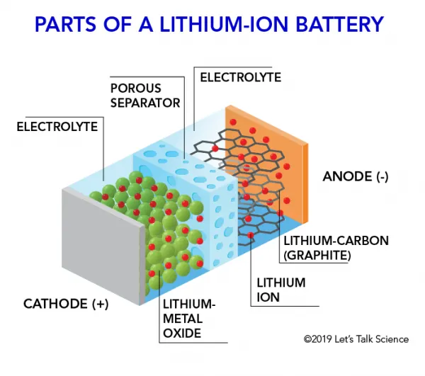
In the batteries, lithium ions move from the negative electrode through an electrolyte to the positive electrode during discharge, and back when charging. Li-ion batteries use an intercalated lithium compound as the material at the positive electrode and typically graphite at the negative electrode. The batteries have a high energy density, no memory effect (other than LFP cells), and low self-discharge. They can however be a safety hazard since they contain flammable electrolytes, and if damaged or incorrectly charged can lead to explosions and fires. Samsung was forced to recall Galaxy Note 7 handsets following lithium-ion fires, and there have been several incidents involving batteries on Boeing 787s.
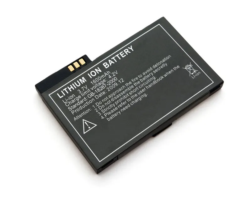
Chemistry, performance, cost, and safety characteristics vary across types of lithium-ion batteries. Handheld electronics mostly use lithium-polymer batteries (with a polymer gel as electrolyte), a lithium cobalt oxide (LiCoO2) cathode material, and a graphite anode, which together offer a high energy density. Lithium iron phosphate (LiFePO4), lithium manganese oxide (LiMn2O4 spinel, or Li2MnO3-based lithium-rich layered materials (LMR-NMC)), and lithium nickel manganese cobalt oxide (LiNiMnCoO2 or NMC) may offer longer lives and may have better rate capability. Such batteries are widely used for electric tools, medical equipment, and other roles. NMC and its derivatives are widely used in electric vehicles.
Research areas for lithium-ion batteries include extending lifetime, increasing energy density, improving safety, reducing cost, and increasing charging speed,[18] among others. Research has been underway in the area of non-flammable electrolytes as a pathway to increased safety based on the flammability and volatility of the organic solvents used in the typical electrolyte. Strategies include aqueous lithium-ion batteries, ceramic solid electrolytes, polymer electrolytes, ionic liquids, and heavily fluorinated systems.
Advantages
- Very low profile - batteries resembling the profile of a credit card are feasible.
- Flexible form factor - manufacturers are not bound by standard cell formats. With high volume, any reasonable size can be produced economically.
- Lightweight-gelled electrolytes enable simplified packaging by eliminating the metal shell.
- Improved safety - more resistant to overcharge; less chance for electrolyte leakage.
Limitations
- Lower energy density and decreased cycle count compared to lithium-ion.
- Expensive to manufacture.
- No standard sizes. Most cells are produced for high-volume consumer markets.
- Higher cost-to-energy ratio than lithium-ion
Procedure:
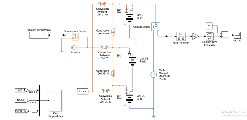
The following figure shows the Simulink model of a 10 cell series lithium-ion battery using an AC Current source providing cyclic charge/discharge profile
The fundamental blocks used in this model are as follows
1. AC Current Source: The AC Current Source block represents an ideal current source that maintains the sinusoidal current through it, independent of the voltage across its terminals.
The output current is defined by the following equation:
`I=I_0 ⋅sin(2π⋅f⋅t+psi)`
This block has two electrical conserving ports associated with its terminals.
2. Current Sensor: The Current Sensor block represents an ideal current sensor, that is, a device that converts current measured in any electrical branch into a physical signal proportional to the current.
Connections '+' and '–' are electrical conserving ports through which the sensor is inserted into the circuit. The connection 'I' is a physical signal port that outputs the measurement result.
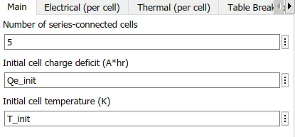
3. Lithium Cells: The Lithium cell block represents an ideal lithium-ion cell used in a battery pack with thermal ports.
Connections '+' and '–' are electrical conserving ports through which the cells are inserted into the circuit. The Thermal port used for further thermal network connections.
Here, the Cells pack 1-4 and 6-10 are normal and healthy cells, whereas Cell 5 is the faulty cell.
4. Temperature Sensor: The Temperature Sensor block represents an ideal temperature sensor, that is, a device that determines the temperature differential measured between two points without drawing any heat. Connections 'A' and 'B' are thermal conserving ports that connect to the two points where the temperature is being monitored. Port 'T' is a physical signal port that outputs the temperature differential value.
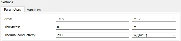
5. Conductive Heat Transfer: The Conductive heat transfer block models heat transfer in a thermal network by conduction through a layer of material. The rate of heat transfer is governed by Fourier's law and is proportional to the temperature difference, material thermal conductivity, area normal to the heat flow direction, and inversely proportional to the layer thickness.
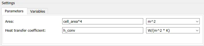
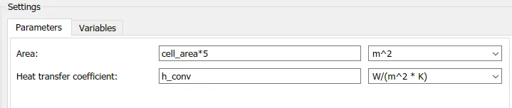
6. Convective Heat Transfer: The Convective heat transfer block models heat transfer in a thermal network by convection due to fluid motion. The rate of heat transfer is proportional to the temperature difference, heat transfer coefficient, and surface area in contact with the fluid.
7. Temperature Source: The Temperature source block represents an ideal energy source in a thermal network that can maintain a constant absolute temperature at the port regardless of the heat flow rate.
8. Rate Transition: Rate Transition block transfers data from the output of a block operating at one rate to the input of another block operating at a different rate. The Rate Transition block's parameters allow you to specify options that trade data integrity and deterministic transfer for faster response and/or lower memory requirements.
9. Discrete-Time Integrator: The Discrete-Time Integrator block implements discrete-time integration or accumulation of the input signal. The block can integrate or accumulate using the Forward Euler, Backward Euler, and Trapezoidal methods.
10. Mux: The Mux block combines inputs with the same data type and complexity into a vector output.
11. Electrical Reference, Thermal Reference, Solver Configuration, Scope, Display, Gain, Constant, Add, PS-Simulink Converter, Simulink-PS Converter, Goto tag, and From are the miscellaneous blocks used in this model.
The three subsystems used in this model for the respective cells pack are as below
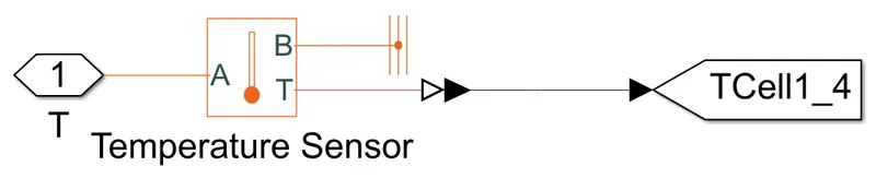
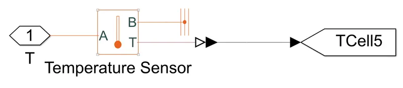
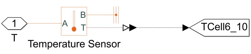
They are all named 'T' and the output of all the subsystems are given to the Goto tags which will show the temperature curves using a Scope.
Model parameters:
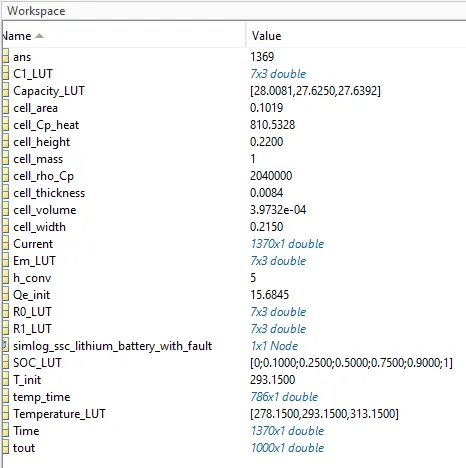
a. From Workspace:
b. AC Current Source:

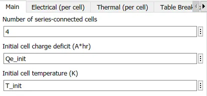
c. Lithium Cells:
For Cells 1-4:
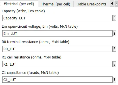
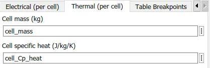
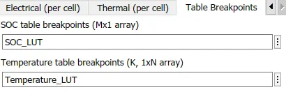
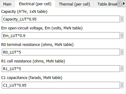
For Cell 5:
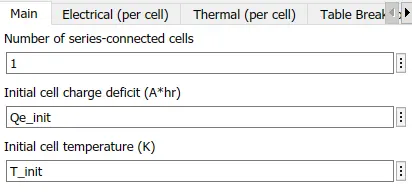
To provide fault in this cell, all the electrical parameters are multiplied by some values
For Cells 6-10:
d. Conductive Heat Transfer (For all cells):
e. Convective Heat Transfer:
For Cells 1-4:
For Cell 5:

For Cells 6-10:
f. Temperature Source:

g. Defined Workspace Parameters:
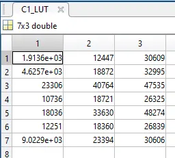
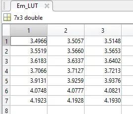
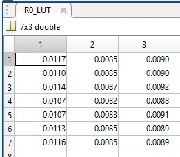
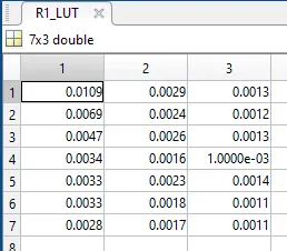
For the Temperature time cycle, refer to the following excel sheet
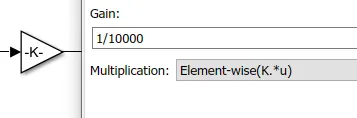
h. Gain value:
Results:
After running the simulation for 7200 secs, we get the following results
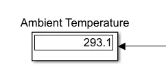
1. Ambient Temperature:
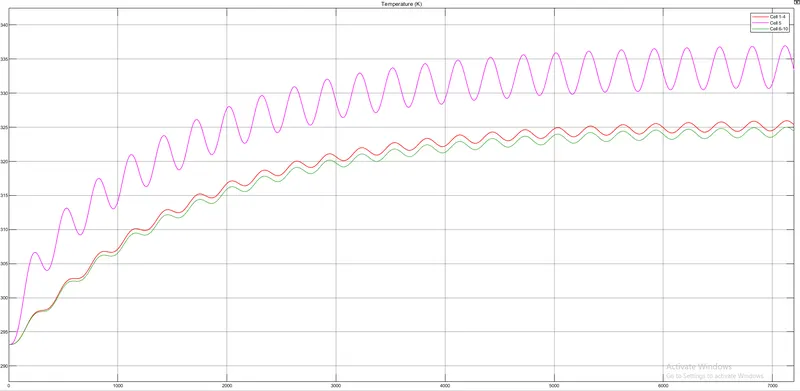
2. Cells Temperature:
3. SOC:
Conclusion:
1. The Ambient temperature provided by the Temperature source is `293.15^oK`
2. The Cell pack 1-4 reaches the maximum temperature of `326^oK`, Cell pack 5 which is the faulty cell reaches the maximum temperature of `337^oK`, and the Cell pack 6-10 reaches the maximum temperature of `325^oK`.
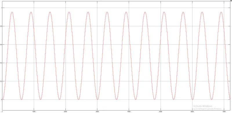
3. The SOC of the model starts from 0 and goes up to 0.95 in 300 secs and again discharges to 0 in 300 secs and the cycle keeps on repeating.
4. The Life cycle of the battery pack is 6 cycles per hour.
The following figure shows the Simulink model of a 10 cell series lithium-ion battery using a Signal Builder which has a signal input using a UDDS drive cycle of the Current profile
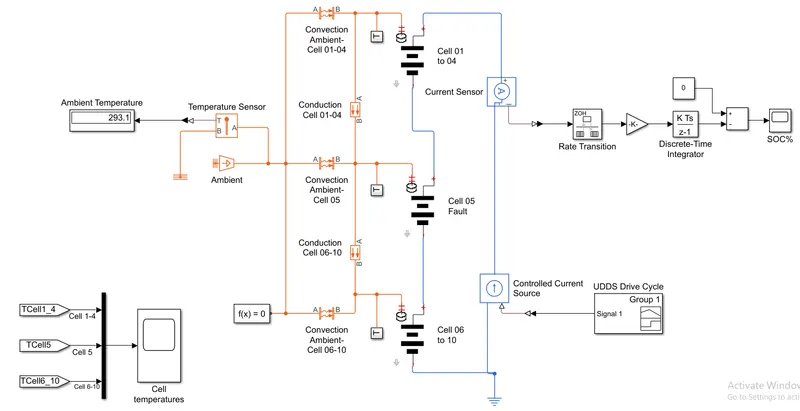
The additional fundamental blocks used in this circuit are
1. Signal builder: The Signal Builder block allows you to create interchangeable groups of piecewise linear signal sources and use them in a model.
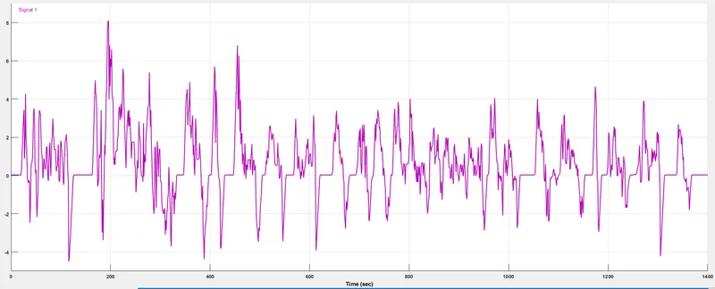
Here, we are using a signal builder block to create the drive cycle data of the UDDS cycle. The limitation of the signal builder is that it accepts data in the form of only the current profile. So, the speed v/s time data from the drive cycle should be converted to its corresponding current profile with respect to time.
The link for the excel sheet of the UDDS drive cycle data with the current profile is as given below
UDDS drive cycle Current profile data
2. Controlled Current Source: This block represents an ideal current source that is powerful enough to maintain the specified current through it regardless of the voltage across it. The output current is I = Is, where Is is the numerical value presented at the physical signal port.
Model parameters:
a. Signal Builder (UDDS drive cycle data with Current profile):
b. Gain value:
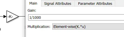
Rest all the parameters remain the same as the above model using a Cyclic AC current source.
Results:
After running the simulation for 1400 secs, we get the following results
1. Ambient Temperature:
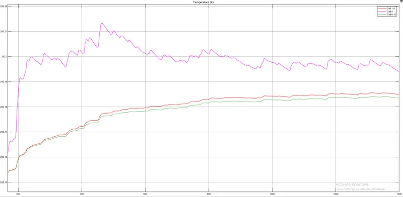
2. Cells Temperature:
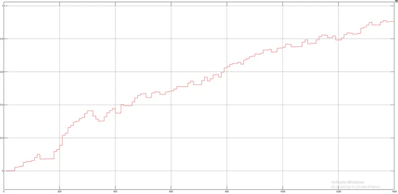
3. SOC:
Conclusion:
1. The Ambient temperature provided by the Temperature source is `293.15^oK`
2. The Cell pack 1-4 reaches the maximum temperature of `293.185^oK`, Cell pack 5 which is the faulty cell reaches the maximum temperature of `293.214^oK`, and the Cell pack 6-10 reaches the maximum temperature of `293.184^oK`.
3. The SOC of the model starts from 0 and goes up to 0.9 in 1400 secs.