Control logic and Stateflow
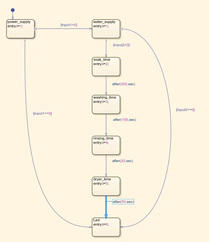
Q1. Implement control logic of a “washing machine” using Stateflow as per given sequence:
- If the power supply is available, the system gets activated
- If the Water supply is not available, stop the process & indicate through LED
- Soaking time should be 200s followed by Washing time of 100s.
- Then rinsing happens for next 20s & dryer runs for 50s
After all the processes have completed turn on the finished LED.
Ans.
Following figure shows the control logic of a 'washing machine' using stateflow
Following figure shows the simulink model used to implement the above control logic of a washing machine when the power is OFF.
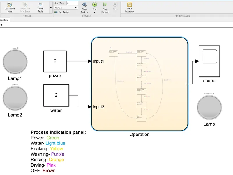
When the power supply is OFF, all the LEDs are in OFF position
Following figure shows the simulink model of a washing machine when the power is ON
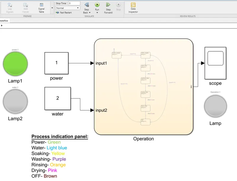
When the power supply is ON, the power indication LED is turned ON and is showing green indication.
Following figure shows the simulink model of a washing model when the water supply is not available
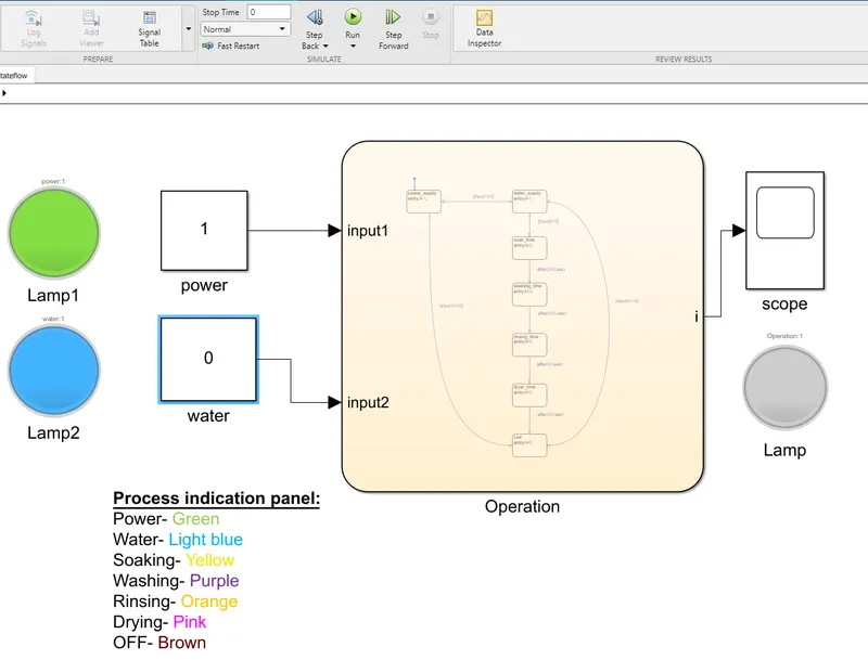
When the power supply is ON but the water supply is not available, the water indication LED is turned ON and is showing light blue indication.
Following figure shows the simulink model when the washing machine is performing the soaking process
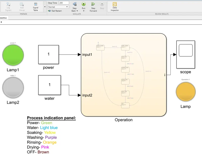
When both the power and water supply is available, the washing machine start performing its fuctions. It starts soaking upto 200 secs and yellow indication is shown at the output LED.
Following figure shows the simulink model when the washing machine is in normal wash mode
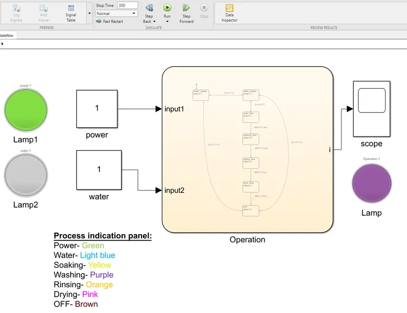
The next function is washing and is performed upto next 100 secs. It is shown by the purple indication.
Following figure shows the simulink model when the washing machine is performing rinsing action
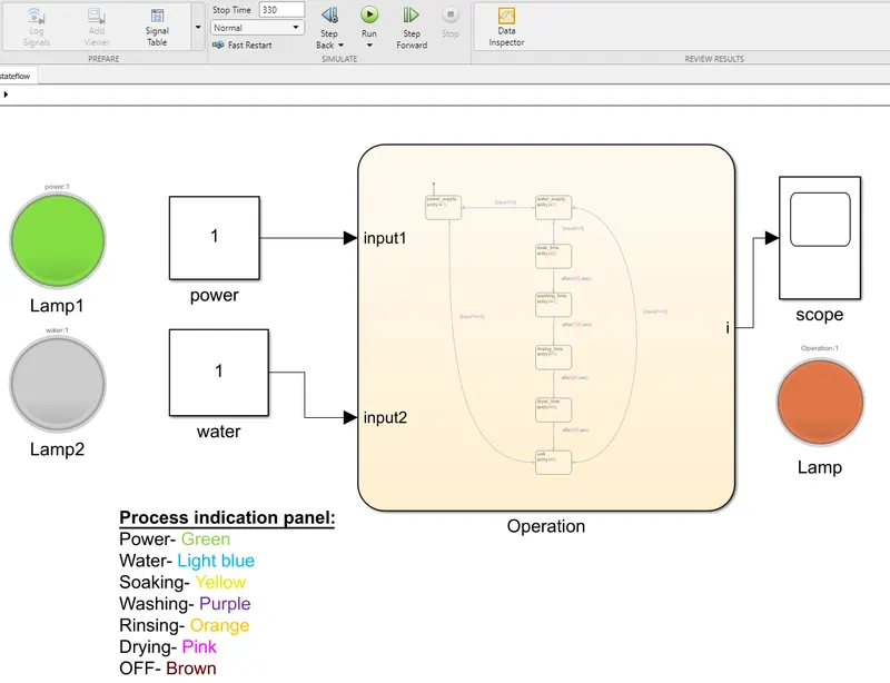
The next function is rinsing and is performed upto next 20 secs. It is shown by the orange indication.
Following figure shows the simulink model when the washing machine is performing drying action
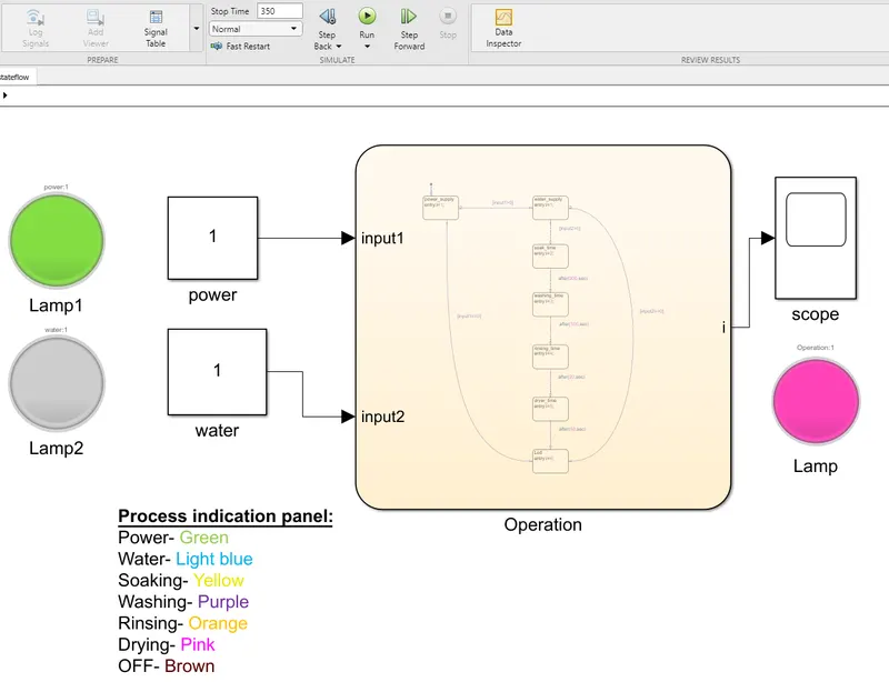
The next function is drying and is performed upto next 50 secs. It is shown by the pink indication.
Following figure shows the simulink model when the washing machine has performed all the functions and is in OFF mode
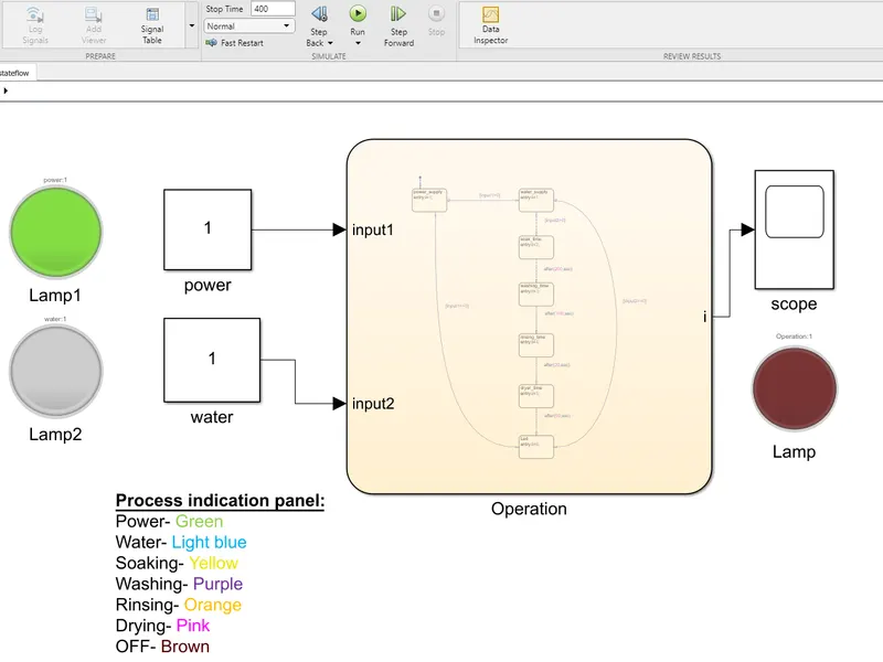
When the washing machine has performed all the functions a brown indication is shown in the LED, thus completing the logic cycle.
Q2. Make a Simulink chart for the “Gear shift” logic as per below conditions:
Speed Range(kmph) Gear
0 to 15 1
16 to 25 2
26 to 40 3
41 to 60 4
Above 61 5
Give speed input while the simulation is running & display the gear number.
Ans.
Following figure shows the control logic of 'Gear shift' using stateflow
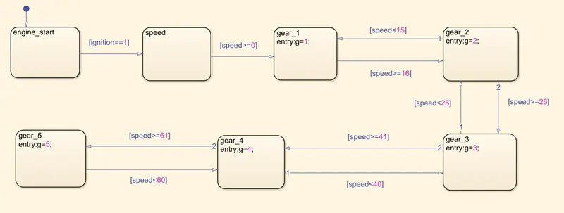
A speedometer is used to give the input speed to the system and according to it the gear is shifted automatically. The Gear shift is shown by both display as well as the indication LEDs.
Following figure shows the simulink model of a gear shift when the input speed is 10km/hr
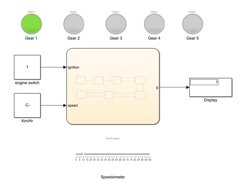
When the input speed is 10km/hr, the system is in 1st gear and the respective LED is turned ON.
Following figure shows the simulink model of a gear shift when input speed is 20km/hr
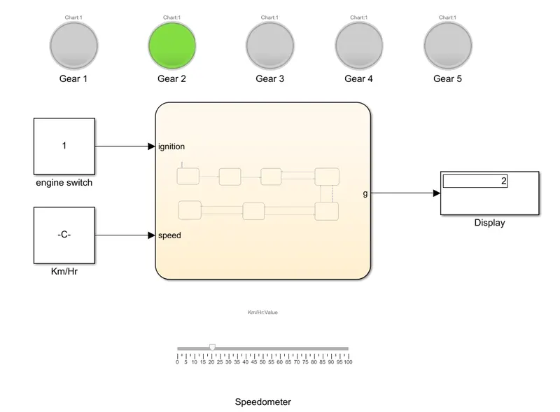
When the input speed is 20km/hr, the system is in 2nd gear and the respective LED is turned ON.
Following figure shows the simulink model of a gear shift when input speed is 30km/hr
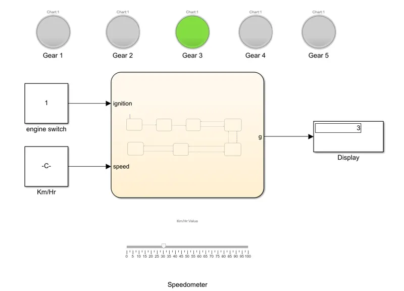
When the input speed is 30km/hr, the system is in 3rd gear and the respective LED is turned ON.
Following figure shows the simulink model of a gear shift when input speed is 50km/hr
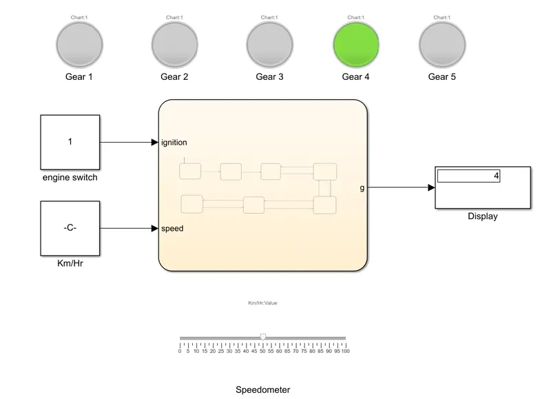
When the input speed is 50km/hr, the system is in 4th gear and the respective LED is turned ON.
Following figure shows the simulink model of a gear shift when input speed is 75km/hr
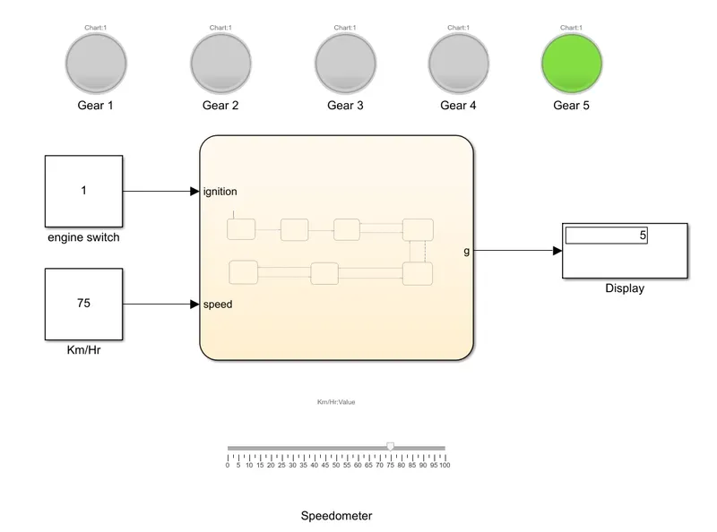
When the input speed is 75km/hr, the system is in 5th gear and the respective LED is turned ON.