Battery Charge-Discharge characteristics
Simulate generic battery model charge-discharge using UDDS data.
Objective: 1. To model the battery
2. To analyze the charge-discharge characteristics for a UDDS drive cycle
Procedure:
A driving cycle is a series of data points representing the speed of the vehicle versus time. Driving cycles are produced by different countries and organizations to assess the performance of the vehicle in various ways, as for example fuel consumption and polluting emissions.
Here, we are using a UDDS drive cycle. UDDS stands for Urban Dynamometer Driving Schedule and refers to the United States Environmental Protection Agency mandated dynamometer test on fuel economy that represents city driving conditions which are used for light-duty vehicle testing.
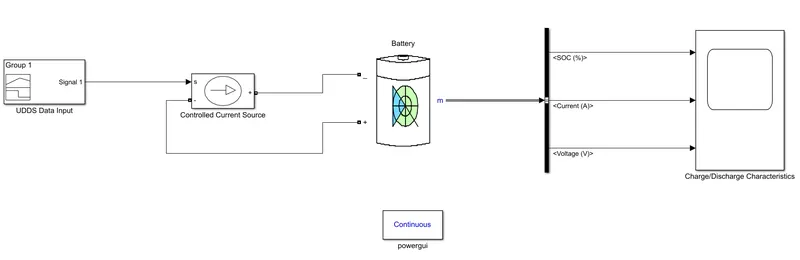
The following are the fundamental blocks used to simulate the generic battery model charge-discharge characteristics using UDDS data
a. Battery: The Battery block implements a generic dynamic model that represents the most popular types of rechargeable batteries.
The parameters of the battery configured are as follows
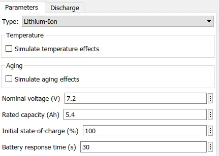
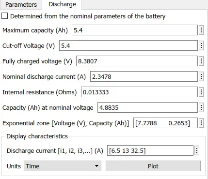
b. Controlled Current Source: The Controlled Current Source block converts the Simulink input signal into an equivalent current source. The generated current is driven by the input signal of the block.
c. Signal Builder: The Signal Builder block allows you to create interchangeable groups of piecewise linear signal sources and use them in a model.
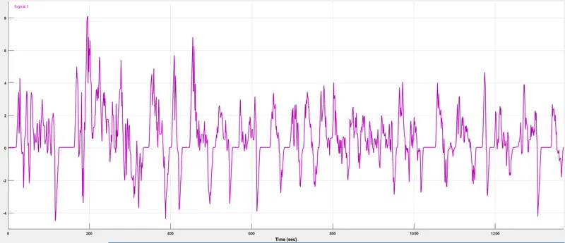
Here, we are using a signal builder block to create the drive cycle data of the UDDS cycle. The limitation of the signal builder is that it accepts data in the form of only the current profile. So, the speed v/s time data from the drive cycle should be converted to its corresponding current profile with respect to time.
The link for the excel sheet of the UDDS drive cycle data with the current profile is as given below
https://docs.google.com/spreadsheets/d/1hN3pJfuIdn4psSIpPWlXtqRgpYs2EcjJ/edit#gid=1816926825
Steps to input the data from the excel sheet into the signal builder block are as follows
- Open the above excel sheet
- Copy the whole 'A' column which represents time in seconds
- Go to the MATLAB command window, and create an array for the above copied time information in 'T'
- Repeat the same procedure for the 'B' column representing current in Amperes and store it in the array 'C'
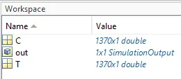
- Go to the signal builder block-> Signal-> New-> custom-> Assign the Time and Y-axis value
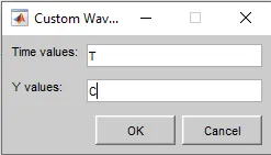
The following figure shows the signal builder input as UDDS drive cycle data provided
d. Bus Selector: The Bus Selector block outputs the elements you select from the input bus. The block can output the selected elements separately or in a new virtual bus.
e. Powergui: The powergui block allows you to choose one of these methods to solve your circuit:
- Continuous, which uses a variable-step solver from Simulink®
- Discretization of the electrical system for a solution at fixed time steps
- Continuous or discrete phasor solution
f. Scope: To display the charge-discharge characteristics of the Simulink model designed.
The following figure shows the Simulink model of a Generic battery for getting its charge-discharge characteristics using UDDS data
Results:
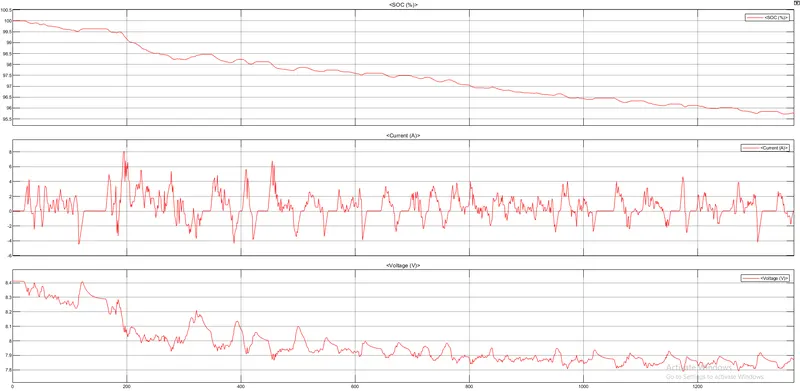
After simulating the above model for the simulation time of 1369 seconds, we get the following results
Conclusion:
1. The SOC of the battery is 95.77%.
2. The maximum amplitude of the current is 8.1 A.
3. The voltage at the start of the cycle is 8.41 V and drops to 7.86 V after the completion of the cycle.