Powertrain for aircraft in runways
Q1. Search and list out the total weight of various types of aircraft.
Ans.
The list of the total weight of various types of aircraft are as follows
| Type | MTOW [kg] | MLW [tonnes] | TOR [m] | LR [m] |
|---|---|---|---|---|
| Antonov An-225 | 640,000 | 591.7 | 3500 | |
| Scaled Composites Model 351 Stratolaunch | 589,670 | 3660 | ||
| Airbus A380-800[1][2][3] | 575,000 | 394 | 3100 | 1930 |
| Boeing 747-8F | 447,700 | 346.091 | 3100 | 1800 |
| Boeing 747-8 | 443,613 | 306.175 | 3100 | |
| Boeing 747-400ER | 412,770 | 295.742 | 3090 | |
| Antonov An-124-100M | 405,060 | 330 | 2520 | 900 |
| Boeing 747-400 | 396,900 | 295.742 | 3018 | 2179 |
| Lockheed C-5 Galaxy[4][5][6] | 381,000 | 288.417 | 2530 | 1494 |
| Boeing 747-200[7] | 377,840 | 285.700 | 3338 | 2109 |
| Boeing 747-300[7] | 377,840 | 260.320 | 3222 | 1905 |
| Airbus A340-500[8] | 371,950 | 240 | 3050 | 2010 |
| Airbus A340-600[8] | 367,400 | 256 | 3100 | 2100 |
| Boeing 777F | 347,800 | 260.816 | 2830 | |
| Boeing 777-300ER | 351,800 | 251.29 | 3100 | |
| Boeing 777-200LR | 347,450 | 223.168 | 3000 | |
| Boeing 747-100[7] | 340,200 | 265.300 | ||
| Airbus A350-1000 | 308,000 | 233.5 | ||
| Boeing 777-300 | 299,370 | 237.683 | 3380 | |
| Boeing 777-200ER | 297,550 | 213.00 | 3380 | 1550 |
| Airbus A340-300[8][9] | 276,700 | 190 | 3000 | 1926 |
| McDonnell Douglas MD-11 | 273,300 | 185 | 2990 | 1890 |
| Airbus A350-900 | 270,000 | 175 | 2670 | 1860 |
| Ilyushin Il-96M | 270,000 | 195.04 | 3115 | 2118 |
| McDonnell Douglas DC-10 | 256,280 | 183 | 2990 | 1890 |
| Boeing 787-9[10] | 254,000 | 192.777 | 2900 | |
| Boeing 787-10[10] | 254,000 | 201.849 | ||
| Airbus A340-200[8][11] | 253,500 | 181 | 2990 | |
| Ilyushin IL-96-300 | 250,000 | 175 | 2600 | 1980 |
| Airbus A330-300[12][13] | 242,000 | 185 | 2500 | 1750 |
| Airbus A330-200[12][13] | 242,000 | 180 | 2220 | 1750 |
| Lockheed L-1011-500 | 231,300 | 166.92 | 2636 | |
| Boeing 787-8[10] | 228,000 | 172.365 | 3300 | 1695 |
| Lockheed L-1011-200 | 211,400 | |||
| Ilyushin IL-86 | 208,000 | 175 | ||
| Boeing 767-400ER | 204,000 | 158.758 | 3414 | |
| Airbus A300-600R[14] | 192,000 | 140 | 2385 | 1555 |
| Boeing 767-300ER | 187,000 | 136.08 | 2713 | 1676 |
| Concorde | 185,000 | 111.1 | 3440 | 2220 |
| Airbus A300-600[14] | 163,000 | 138 | 2324 | 1536 |
| Boeing 767-300 | 159,000 | 136.078 | 2713 | 1676 |
| Airbus A310-300[14] | 157,000 | 124 | 2290 | 1490 |
| Vickers VC10 | 152,000 | 151.9 | ||
| Boeing 707-320B[15] | 151,000 | 97.5 | ||
| Boeing 707-320C[15] | 151,000 | 112.1 | ||
| Douglas DC-8-61 | 147,000 | |||
| Airbus A310-200[14] | 142,000 | 123 | 1860 | 1480 |
| Airbus A400M | 141,000 | 122 | 980 | 770 |
| Douglas DC-8-32 | 140,000 | |||
| Douglas DC-8-51 | 125,000 | |||
| Boeing 757-300 | 124,000 | 101.6 | 2550 | 1750 |
| Boeing 707-120B[15] | 117,000 | 86.3 | ||
| Boeing 757-200 | 116,000 | 89.9 | 2347 | 1555 |
| Boeing 720B[16] | 106,000 | 79.5 | ||
| Boeing 720[16] | 104,000 | 79.5 | ||
| Tupolev Tu-154M | 104,000 | 80 | ||
| Tupolev Tu-204SM | 104,000 | 87.5 | 2250 | |
| Convair 880 | 87,500 | |||
| Boeing 737-900 | 85,000 | 66.36 | 2500 | 1704 |
| Boeing 737-900ER | 85,000 | 71.35 | 2804 | 1829 |
| Boeing 727-200 Advanced[17] | 84,000 | 70.1 | ||
| Airbus A321-100[18] | 83,000 | 77.8 | 2200 | 1540 |
| Boeing 737-800 | 79,000 | 65.32 | 2308 | 1634 |
| Boeing 727-200[17] | 78,000 | 68.1 | ||
| McDonnell-Douglas MD-83 | 73,000 | 63.28 | ||
| Boeing 727-100[17] | 72,500 | 62.4 | ||
| Boeing 727-100C[17] | 72,500 | 62.4 | ||
| McDonnell-Douglas MD-90-30 | 71,000 | 64.41 | 2165 | 1520 |
| de Havilland Comet 4 | 70,700 | |||
| Boeing 737-700 | 70,000 | 58.06 | 1921 | 1415 |
| Airbus A320-100[18] | 68,000 | 66 | 1955 | 1490 |
| Boeing 737-400 | 68,000 | 54.9 | 2540 | 1540 |
| de Havilland Comet 3 | 68,000 | |||
| Boeing 377 | 67,000 | |||
| Boeing 737-600 | 66,000 | 54.66 | 1796 | 1340 |
| Airbus A220-300 | 65,000 | 57.61 | 1890 | 1494 |
| Hawker Siddeley Trident 2E | 65,000 | |||
| Airbus A319[18] | 64,000 | 62.5 | 1850 | 1470 |
| Boeing 737-300 | 63,000 | 51.7 | 1939 | 1396 |
| Boeing 737-500 | 60,000 | 49.9 | 1832 | 1360 |
| Airbus A220-100 | 59,000 | 50.80 | 1463 | 1356 |
| Airbus A318[18] | 59,000 | 57.5 | 1375 | 1340 |
| Boeing 717-200HGW | 55,000 | 47.174 | 1950 | |
| Douglas DC-7 | 55,000 | |||
| de Havilland Comet 2 | 54,000 | |||
| Boeing 717-200BGW | 50,000 | 46.265 | 1950 | |
| de Havilland Comet 1 | 50,000 | |||
| Douglas DC-6A | 48,600 | |||
| Douglas DC-6B | 48,500 | |||
| Embraer 190[19] | 48,000 | 43 | 2056 | 1323 |
| Caravelle III | 46,000 | |||
| Fokker 100 | 46,000 | 39.95 | 1621 | 1350 |
| Douglas DC-6 | 44,000 | |||
| Avro RJ-85 | 42,000 | 36.74 | ||
| Handley Page Hermes | 39,000 | |||
| Embraer 175[20] | 37,500 | 32.8 | 2244 | 1304 |
| Bombardier CRJ900[21] | 36,500 | 33.345 | 1778 | 1596 |
| Embraer 170[22] | 36,000 | 32.8 | 1644 | 1274 |
| Bombardier CRJ700 | 33,000 | 30.39 | 1564 | 1478 |
| Douglas DC-4 | 33,000 | |||
| Vickers Viscount 800 | 30,400 | |||
| Bombardier Q400 | 28,000 | 28.01 | 1219 | 1295 |
| Bombardier CRJ200 | 23,000 | 21.319 | 1918 | 1479 |
| ATR 72-600 | 22,800 | 22.35 | 1333 | 914 |
| Saab 2000 | 22,800 | 21.5 | 1300 | |
| Embraer ERJ 145 | 22,000 | 19.3 | 2270 | 1380 |
| ATR 42-500 | 18,600 | 18.3 | 1165 | 1126 |
| Saab 340 | 13,150 | 12.930 | 1300 | 1030 |
| Embraer 120 Brasilia | 11,500 | 11.25 | 1560 | 1380 |
| BAe Jetstream 41 | 10,890 | 10.570 | 1493 | 826 |
| Learjet 75[23] | 9,752 | 8.709 | 1353 | 811 |
| Pilatus PC-24[24] | 8,300 | 7.665 | 893 | 724 |
| Embraer Phenom 300[25] | 8,150 | 7.65 | 956 | 677 |
| Beechcraft 1900D | 7,765 | 7.605 | 1036 | 853 |
| Cessna Citation CJ4[26] | 7,761 | 7.103 | 1039 | 896 |
| de Havilland Hercules | 7,000 | |||
| Embraer Phenom 100 | 4,800 | 4.43 | 975 | 741 |
Where MTOW = Maximum take-off weight
MLW = Maximum landing weight
TOR = Take-off run
LR = Landing run
Q2. Is there any difference between ground speed and airspeed?
Ans.
Ground speed:
Ground speed is the horizontal speed of an aircraft relative to the Earth’s surface. It is vital for accurate navigation to the destination that the pilot has an estimate of the ground speed that will be achieved during a flight.
An aircraft diving vertically would have a ground speed of zero. The information displayed to passengers through the entertainment system of airline aircraft usually gives the aircraft ground speed rather than airspeed.
Ground speed can be determined by the vector sum of the aircraft's true airspeed and the current wind speed and direction; a headwind subtracts from the ground speed, while a tailwind adds to it. Winds at other angles to the heading will have components of either headwind or tailwind as well as a crosswind component.
An airspeed indicator indicates the aircraft's speed relative to the air mass. The air mass may be moving over the ground due to wind, and therefore some additional means to provide position over the ground is required. This might be through navigation using landmarks, radio aided position location, an inertial navigation system, or GPS. When more advanced technology is unavailable, an E6B flight computer may be used to calculate ground speed. Ground speed radar can measure it directly.
Ground speed is quite different from airspeed. When an aircraft is airborne the ground speed does not determine when the aircraft will stall, and it doesn't influence the aircraft performance such as the rate of climb.
Airspeed:
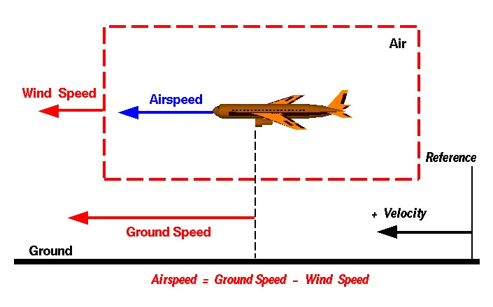
The important quantity in the generation of lift is the relative velocity between the object and the air, which is called the airspeed. Airspeed cannot be directly measured from a ground position but must be computed from the ground speed and the wind speed. Airspeed is the vector difference between the ground speed and the wind speed.
Airspeed = Ground Speed - Wind Speed
On a perfectly still day, the airspeed is equal to the ground speed. But if the wind is blowing in the same direction that the aircraft is moving, the airspeed will be less than the ground speed.
Q3. Why is it not recommended to use aircraft engine power to move it on the ground at the Airport?
Ans.
Taxiing is the movement of an aircraft on the ground, under its own power, in contrast to towing or pushback where the aircraft is moved by a tug. An airplane uses taxiways to taxi from one place on an airport to another; for example, when moving from a hangar to the runway. The term 'taxiing' is not used for the accelerating run along a runway before takeoff, or the decelerating run immediately after landing, which is called the takeoff roll and landing rollout, respectively.
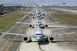
We are assuming passenger commuter aircraft and large airliners. Aircraft move using their own engine power all the time on the airport apron and taxiways under their own power to go towards runways and after landing taxi to their assigned gate.
The only time they use external assistance is to pushback from the gate. Large turbofan aircraft need help to reverse via a pushback tractor. The engines are turned on after the pushback is complete and the aircraft can move forward under Its own power.
To be accurate, some aircraft can reverse using a variable pitch prop or thrust reversing on turbofans but generally reversing is done via pushback tractors. Blasting jet reversers blows debris In the crowded gate area creating foreign object damage hazard for adjacent aircraft, gate equipment, or terminal waiting area glass windows.
Q4. How an aircraft is pushed to the runway when it's ready to take off?
Ans.
An aircraft is pushed to the runway in the following manner
Towing:
Aircraft towing is a frequent and vital operation around any airport. Towing may be needed for the movement of active or disabled aircraft on airport ramps or in moving aircraft in and out of hangers for maintenance procedures or storage.
Towing aircraft can be dangerous and damage to the aircraft, other objects, or injuries to towing team members is possible if the proper procedures are not followed. Most towing accidents are preventable by the proper handling of the aircraft, maintaining situational awareness, and practicing patience. Towing accidents cannot only result in aircraft damage but can also delay or cancel flights or lead to other airport disruptions.
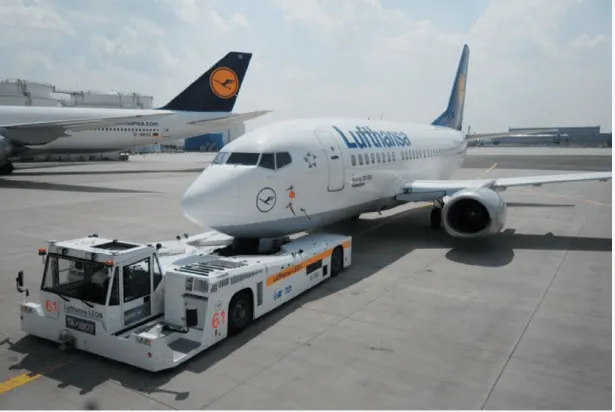
Movement of moving most aircraft around the airport and hangars is usually accomplished by towing with a towing vehicle or ‘tug’. The aircraft is attached to the tow vehicle by the use of a towbar or other specialized methods that connect to or raise the nose or landing gear off the ground.
Detailed towing instructions for each different model of aircraft are located in the manufacturer’s maintenance instructions and each towing operator should have established procedures that are to be used for the towing process as a part of the overall safety program. The aircraft towing personnel must be familiar with all published towing procedures about the type of aircraft being towed and any specific airport regulations regarding the ground movement of aircraft. All towing personnel must be properly trained to perform the procedures and there need to be mandatory requirements for the initial, recurrent, and remedial training for all personnel involved with the towing process.
Taxiing:
Taxiing is the movement of an aircraft on the ground, under its own power, in contrast to towing or pushback where the aircraft is moved by a tug. An airplane uses taxiways to taxi from one place on an airport to another; for example, when moving from a hangar to the runway. The term 'taxiing' is not used for the accelerating run along a runway before takeoff, or the decelerating run immediately after landing, which is called the takeoff roll and landing rollout, respectively.
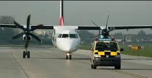
Takeoff:
Following the taxiway, the aircraft reach the runway. Takeoff is the phase of flight in which an aircraft goes through a transition from moving along the ground(taxiing) to flying in the air, usually starting on a runway. Usually, the engines are run at full power during takeoff. Following the taxi motion, the aircraft stops at the starting line of the runway. Before takeoff, the engines, particularly piston engines, are routinely run up at high power to check for engine-related problems. When the pilot releases the brakes, the aircraft starts accelerating rapidly until the necessary speed for takeoff is achieved.
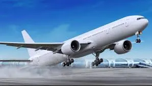
The required takeoff speed varies with air density, aircraft weight, and aircraft configuration. Air density is affected by factors such as field elevation and air temperature.
Q5. Learn about take-off power, tire design, rolling resistance, tire pressure, brake forces when landing.
Ans.
Take-off power:
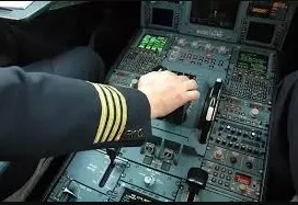
The amount of power that an engine is allowed to produce for a limited period of time for takeoff. The use of takeoff power is usually limited to 5 min for reciprocating engines and up to 2½ min for gas turbine engines. This may not always be the case. Specifically, for reciprocating engines, it is the brake horsepower developed under standard, sea-level conditions, and the maximum conditions of the crankshaft rotational speed and the engine manifold pressure approved for the normal take-off. It is limited in continuous use to the period of time shown in the approved engine specifications. For gas turbine engines, it is the thrust developed under static conditions at a specified altitude and atmospheric conditions of the rotor shaft rotational speed and gas temperature approved for the normal takeoff. It is limited in continuous use to the period of time shown in the approved engine specifications.
Tire_design:
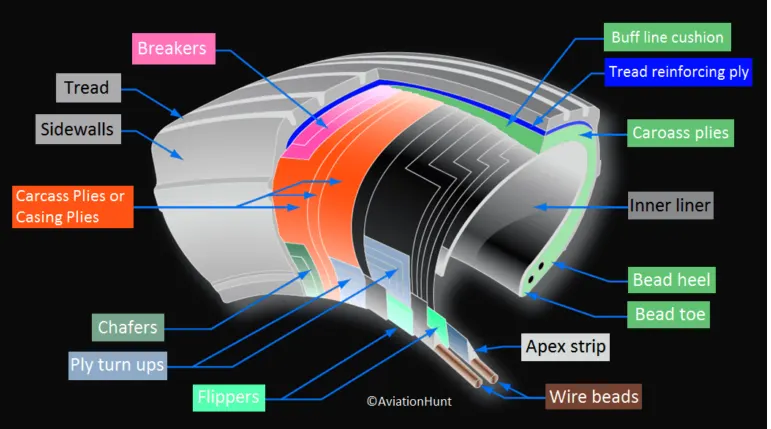
When it comes to safety, tires are one of the most important components of aircraft. They help to absorb the shock of landing and provide cushioning. It also provides the necessary traction for braking and stopping of an aircraft.
An aircraft tire is designed to withstand extremely heavy loads while landing, take off, taxing, and parking. The number of wheels required for aircraft increases with the weight of the aircraft, as the weight of the airplane needs to be distributed more evenly.
A Boeing 737NG & 737MAX uses 6 wheels, Boeing 787 uses 10 wheels, Boeing 777 uses 14 wheels and Airbus A380 uses 22 wheels. Aircraft tires work under extreme conditions, carrying up to 340 tons and accelerating at over 250 km/hour at takeoff, in addition to enduring varied environmental stress when in flight and taxiing.
Carcass plies are used to form the tire. They are sometimes called casing plies. An aircraft tire is constructed for the purpose it serves.
- They support the weight of an aircraft while it is on the ground.
- It also provides the necessary traction for braking and stopping of an airplane.
- Tyre also helps to absorb the shock of landing and provide cushioning for the roughness of takeoff, roll-out, and taxi operations.
Unlike an automobile or truck tire, it does not have to carry a load for a long period of continuous operation. However, an aircraft tire absorbs the high impact loads of landing, and also it’s operating at high speeds for a short time when required.
Rolling resistance:
Rolling resistance sometimes called rolling friction or rolling drag is the force resisting the motion when a body (such as a ball, tire, or wheel) rolls on a surface. It is mainly caused by non-elastic effects; that is, not all the energy needed for deformation (or movement) of the wheel, roadbed, etc., is recovered when the pressure is removed. Two forms of this are hysteresis losses (see below), and permanent (plastic) deformation of the object or the surface (e.g. soil).
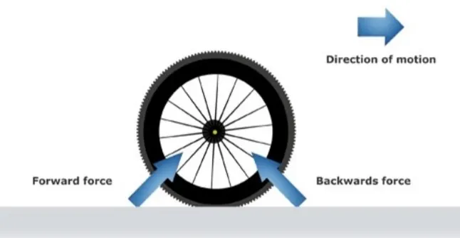
Rolling resistance happens because the force pushing back against the tire as it comes into contact with the road is bigger than the force pushing forward as it leaves.
As the front part of the tire touches the road, it takes a lot of force to squeeze in the tire. This causes a backward force on the wheel. As the tire comes back off the road, there is a force pushing forward on the wheel, but this forward force is not enough. This is because of internal friction in the tire.
If you could design a tire that didn't have internal friction and didn't heat up, the force at the front section of the tire contacting the road would be the same size as the force on the back section. This would mean zero rolling resistance, assuming there was no energy loss due to compression of the road surface.
Tire pressure:
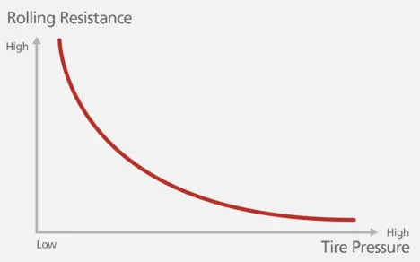
An aircraft tire or tire is designed to withstand extremely heavy loads for short durations. The number of tires required for aircraft increases with the weight of the aircraft, as the weight of the airplane needs to be distributed more evenly. Aircraft tire tread patterns are designed to facilitate stability in high crosswind conditions, to channel water away to prevent hydroplaning, and for braking effect.
Aircraft tires also include fusible plugs (which are assembled on the inside of the wheels), designed to melt at a certain temperature. Tires often overheat if maximum braking is applied during an aborted takeoff or an emergency landing. The fuses provide a safer failure mode that prevents tire explosions by deflating in a controlled manner, thus minimizing damage to aircraft and objects in the surrounding environment.
Each of the twelve Boeing 777-300ER main tires is inflated to 220 psi (15 bar; 1,500 kPa), weighs 120 kg (260 lb), has a diameter of 134 cm (53 in), and is changed every 300 cycles while the brakes are changed every 2000 cycles. Each tire is worth about $5,000. Aircraft tires generally operate at high pressures, up to 200 psi (14 bar; 1,400 kPa) for airliners, and even higher for business jets[citation needed]. The main landing gear on the Concorde was typically inflated to 232 psi (16.0 bar), whilst its tail bumper gear tires were as high as 294 psi (20.3 bar). The high pressure and weight load on the Concorde tires were a significant factor in the loss of Air France Flight 4590.
Tests of airliner aircraft tires have shown that they can sustain pressures of a maximum 800 psi (55 bar; 5,500 kPa) before bursting.[citation needed] During the tests the tires have to be filled with water, to prevent the test room from being blown apart by the energy that would be released by gas when the tire bursts.
Aircraft tires are usually inflated with nitrogen to minimize expansion and contraction from extreme changes in ambient temperature and pressure experienced during flight. Dry nitrogen expands at the same rate as other dry atmospheric gases (normal air is about 80% nitrogen), but common compressed air sources may contain moisture, which increases the expansion rate with temperature.
The requirement that an inert gas, such as nitrogen, be used instead of air for inflation of tires on certain transport category airplanes was prompted by at least three cases in which the oxygen in air-filled tires had combined with volatile gases given off by a severely overheated tire and exploded upon reaching autoignition temperature. The use of inert gas for tire inflation eliminates the possibility of a tire explosion.
Brakes forces when landing:
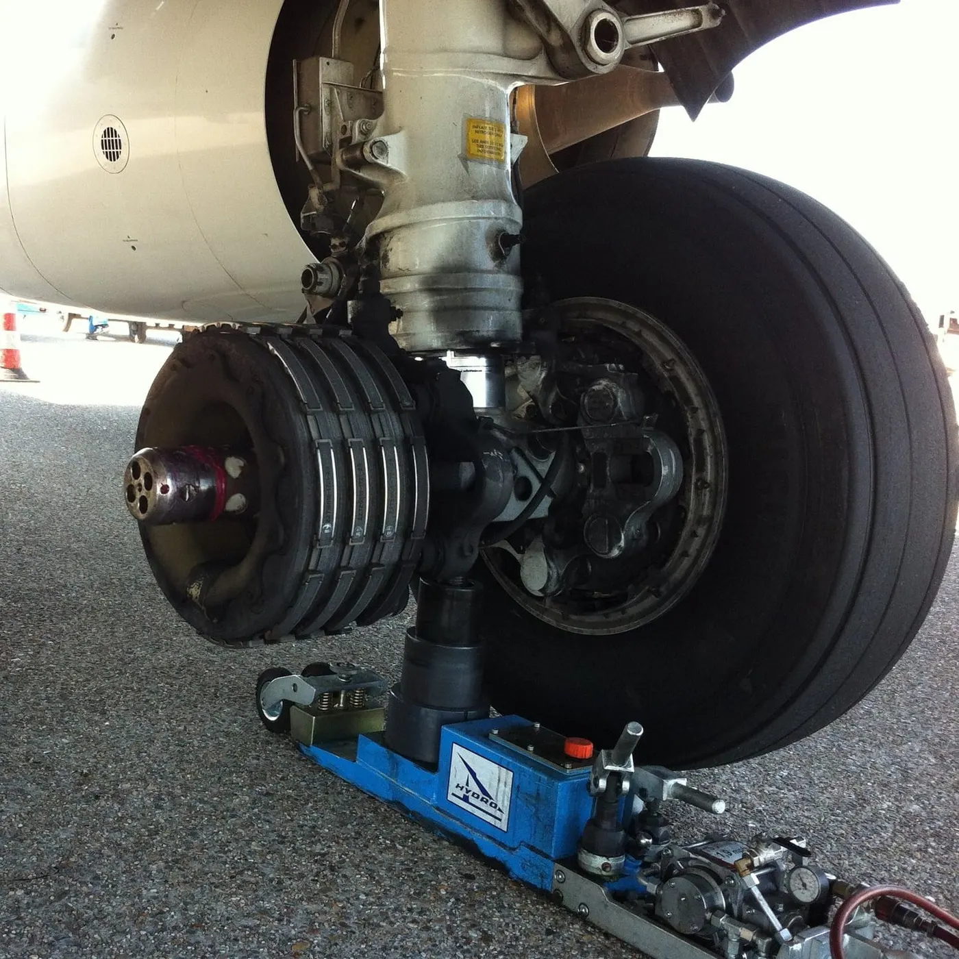
Aircraft brakes stop a moving aircraft by converting its kinetic energy to heat energy through friction between rotating and stationary discs located in brake assemblies in the wheels.
Brakes provide this critical stopping function during landings to enable airplanes to stop within the length of the runway. They also stop aircraft during rejected takeoff events, in which an attempted takeoff is canceled as the airplane is rolling down the runway before it lifts off from the ground due to engine failure, tire blowout, another system failure, or direction from air traffic control.
Aircraft brakes also prevent motion of the aircraft when it is parked, limit its speed during taxiing, and can even help steer the aircraft on the ground by applying different levels of braking force to the left- and right-side brakes.
Aircraft brakes work in conjunction with other brake mechanisms such as thrust reversers, air brakes, and spoilers. Thrust reversers are surfaces that are deployed into the path of the jet blast from the engines to redirect propulsive thrust in a direction that opposes the motion of the aircraft. Air brakes and spoilers are flight control surfaces that create additional aerodynamic drag when deployed into the path of air flowing around the aircraft.
How aircraft brakes work
The most common type of brake used on aircraft is the disc brake. Disc brakes function by exploiting friction between rotating and stationary discs inside the brake.
Upon receiving a command signal to brake — from the pilot depressing a foot pedal or from the auto brake system — actuators in the brake move a piston to squeeze the discs together, generating a frictional force that slows the rotation of the wheel. The friction between the discs generates heat as the aircraft’s kinetic energy is converted to heat energy. In this function, the brakes act as a heat sink, absorbing tremendous amounts of heat as the aircraft sheds kinetic energy. During RTO stops, the temperature of carbon disc brakes can exceed 1,800° C.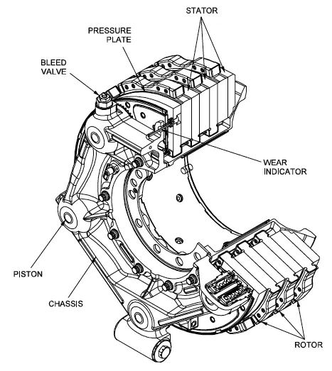
The discs are mounted on a carrier assembly consisting of a torque tube, which resists and transmits brake torque to the landing gear structure. Sandwiched together between the carrier assembly housing and a backing plate, the discs are arranged in an alternating pattern of rotors and stators. Notch and groove geometry around the circumference of each rotor fits into corresponding geometry in the wheel, keying the rotors to the wheel so that they rotate with it. The stators are keyed to the torque tube and are thus held stationary since the torque tube is connected to the axle and landing gear structure.
Cylindrical spaces within the carrier assembly hold actuator pistons. Braking occurs as piston force squeezes the discs together.
During each application of the brakes, the disc material is worn away by frictional forces. A wear indicator in the form of a pin that protrudes out of the carrier assembly indicates the thickness of the stack of discs. Over hundreds of brake applications, the material wears away and discs become thinner, requiring replacement following periodic maintenance intervals.
Q6. With necessary assumptions, calculate the force and power required to push/pull an aircraft by a towing vehicle.
Ans.
a. Rolling Resistance Force
The rolling resistance force is mainly experienced by the tire when the vehicle moves over any surface.
The rolling resistance force is given by the expression
`F_(rr)=mu_(rr)*M*g`
Where `mu_(rr)`= coefficient of rolling resistance
M*g = weight in Newtons
The coefficient of rolling resistance depends on many factors like tire pressure, the material of the tire, thread pattern of the tire, temperature of the tire, and road roughness and liquids on the road.
Here, we are taking the heaviest flight as a reference to design our electric-powered towing tractor because if we design for heavy application all the light aircraft can push/pulled too.
Solution:
Weight of the aircraft (Antonov-AN 225) = 640000 kg
Weight of the towing tractor = 50000 kg (To provide enough traction)
Rolling resistance coefficient of towing vehicle (`mu_(rr)`) = 0.002 (Assume)
Rolling resistance coefficient of an aircraft tire (`mu_(rr)`) = 0.005 (Assume)
Rolling resistance force of towing tractor = `mu_(rr)*M*g`
= 0.002*50000*9.81
= 981 N
Rolling resistance force of aircraft = `mu_(rr)*M*g`
= 0.005*640000*9.81
= 31392 N
Total rolling resistance force = Rolling resistance force of aircraft + Rolling resistance force of towing tractor
= 981 + 31392
= 32373 N
= 32.373 KN
b. Air drag force
The air drag force is the force that occurs due to air striking effects on the vehicle when it moves.
The vehicle moves through an air medium of a particular density value with a certain speed, this causes the air to strike against the vehicle and it causes a drag on the vehicle.
The aerodynamic drag force is given by the expression
`F_(ad)= 1/2*rho*A*V^2*C_d`
Where `rho` = density of air medium
A = frontal area of the vehicle
V = Velocity of the vehicle
`C_d` = drag coefficient
Solution:
The velocity of the aircraft while towing = 30 kmph = 8.33 m/s (Assume)
The density of Air medium = 1.3 (Assume)
The frontal area of the aircraft = 20 `m^2` (Assume)
The frontal area of the towing vehicle = 5 `m^2` (Assume)
The drag coefficient of the aircraft = 0.025 (Assume)
The drag coefficient of the towing vehicle = 0.015 (Assume)
Air drag force of aircraft = `1/2*rho*A*V^2*C_d`
= `1/2*1.3*20*30^2*0.025`
= 292.5 N
Air drag force of towing vehicle = `1/2*rho*A*V^2*C_d`
= `1/2*1.3*5*30^2*0.015`
= 43.875 N
Total Air Drag force = Air drag force of aircraft + Air Drag force of towing vehicle
= 292.5 + 43.875
= 336.375 N
= 0.336 KN
Therefore, the total force that the motor needs to overcome = Rolling resistance force + Air drag force
= 32.373 + 0.336
= 32.709 KN
c. Power requirement
The power required by the motor is given by the velocity with which the towing operation takes place.
The average speed of push/pull = 25 kmph = 6.95 m/s (Assume)
The power required by the motor = Total forces * push/pull velocity
= 32.709*6.95
= 227.32755 KW
We know that the total tractive force (`F_(te)`) = T * G/r
Where T = output torque
G = Gear ratio
r = radius of tire
For a heavy-duty towing tractor, we assume
G = 11 (for delivering high torque)
r = 30 inches = 0.762 m
Therefore, `T= (F_(te)*r)/G`
`T=(32.709*0.762)/11`
T = 2.2658 KN-m
Results: The total tractive force, the power required, and the torque required to push/pull an aircraft by a towing vehicle are 32.709 KN, 227.32755 KW, and 2.2658 KN-m respectively.
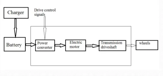
Q7. Design an electric powertrain with the type of motor, its power rating, and the energy requirement to fulfill aircraft towing applications. Estimate the duty cycle range to control the aircraft speed from zero to highest. Make all required assumptions. Prepare a table of assumed parameters. Draw a block diagram of the powertrain.
Ans.
Taking values of some parameters calculated in the previous question as a reference for this question.
Energy is the capacity to do work. Energy is power integrated over time.
Assuming the operational time of the Towing truck to be around 12 minutes for one cycle
12 minutes = 0.2 hours
Therefore, Energy = Power * Time
= 227 * 0.2
= 45.4 KW/hr
Therefore, the battery must be able to store the energy of 45.4 KW/hr and should deliver the energy throughout the run time for the motor to produce 2.26 KN-m of torque instantaneously.
Thus the storage of energy in batteries with high-performance ultracapacitors is selected to fulfill the required power delivery.
Motor selection:
Here we have selected a Brushless DC Motor that has a power rating of 227 KW and with the proper gear ratio and transmission, it should be able to deliver 2.26 KN-m of torque instantaneously.
Assuming the Battery armature voltage = 450 V
And Battery armature current = 350 A
For getting the maximum output from the motor (227 KW), the voltage applied to the motor terminals must be 900 Volts at the positive and negative terminals.
Here we are using a DC-DC Boost Converter to upscale the voltage level from the battery to the required level so that when supplied to the motor we can get the desired power output from the motor.
The boost converter converts the 400 V of the armature voltage to a high voltage level of 1000 V.
Accordingly, a battery of 250 KW power rating is selected for supplying to the motor of 227 KW rating.
Therefore, the duty cycle range to control the speed from 0 to max speed (here 6.95 m/s) is
d = Required power/ Rated power = `227/250` = 0.908
This means the controller should provide a duty cycle ranging from 0 to 90.8% to control the towing speed.
Now, Motor terminal voltage = Armature voltage * Duty cycle
= 1000 * 0.908
= 908 V
Since Motor terminal voltage > Required voltage
With 90.8% of duty cycle the voltage at Motor terminals = 900 V, which gives the full power with all gearings instantaneously.
Thus, by varying the Duty Cycle value the speed of towing vehicle is controlled.
The table for all the assumed parameters is as below
| Parameter | Value |
| Mass of Aircraft (kg) | 640000 |
| Mass of Towing vehicle (kg) | 50000 |
| Coefficient of rolling resistance for Aircraft | 0.002 |
| Coefficient of rolling resistance for Towing vehicle | 0.005 |
| Drag coefficient for Aircraft | 0.025 |
| Drag coefficient for Towing vehicle | 0.015 |
| Frontal area of Aircraft (m^2) | 20 |
| Frontal area of Towing vehicle (m^2) | 5 |
| Towing speed (kmph) | 30 |
| Air density | 1.3 |
| Time for towing (secs) | 12 |
| Tire radius (inches) | 30 |
| Gear ratio | 11 |
| Battery rating (KW) | 250 |
Block diagram of the powertrain designed is as below