Performed Batch meshing for a 'car hood assembly' using HYPERMESH
AIM
To Perform Batch-meshing on the given components (Fender & Hood assembly - BIW component) with the given criteria and assign the non-linear material property Steel for Radioss profile to them.
GIVEN DATA
- CAD Model.
- Quality Criteria.
- Parametric file.
1. CAD MODEL:
Here the given cad model are BIW Components,
- Fender
- Hood Assembly
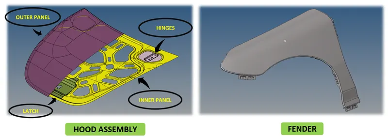
Figure 1. CAD MODEL - Given data
2. QUALITY CRITERIA:
Target Element Length = 5 Units
| S.N | Quality Criteria | Value |
| 1 | Aspect Ratio | 5 |
| 2 | Skewness | 45 |
| 3 | Warping | 15 |
| 4 | Taper | 0.5 |
| 5 | Min. Length | 2 Units |
| 6 | Max. Length | 8 Units |
| 7 | Min angle Quad | 45 |
| 8 | Max angle Quad | 135 |
| 9 | Min angle Tria | 20 |
| 10 | Max angle Tria | 120 |
| 10 | Tria % | 10 |
Table 1. Quality Criteria
3. Parametric File:
“Crash 5mm” parametric file
THEORY - BATCH MESH:
- Batch mesh ia a automated mesh where time generated to mesh is less while compared to traditional automesh.
- For large and assemblies batch mesh can be performed and its a role of CAE engineers to cross check the captured feature with cad model.
- If wrongly captured of feature has been found CAE engineer must make changes manually.
- Also it is an engineers role to clear the tria concentrations & to eliminate the quality failure if found.
- Also the mesh flow must be done manually in some areas.
- Batch mesh will generate both mid surface as well as mesh.
PROCEDURE:
BATCH MESH
Step 1: Import CAD model
Figure 1. CAD MODEL - import data
Step 2: Duplicate the Cad component - As the batch mesh deletes the original cad surfaces and gives only the mid surfaces & mesh duplicating the cad component will help us to cross check the original CAD withthe mid surfaces.
Step 3: Batch Mesh - Go to 2D --> Automesh ---> Batch mesh ---> Import the Parametric file & Criteria file ---> Mesh.
- “Crash 5mm” parametric file is used for this project.
- Criteria file should be set by Go to ---> preferences ---> Criteria file settings ---> Change the given criteria ---> Save. This saved file will be importing in criteria file setting while batch meshing.
- MID SURFACE & MESHING will be automatically generated once after performing batch mesh directly on the cad.
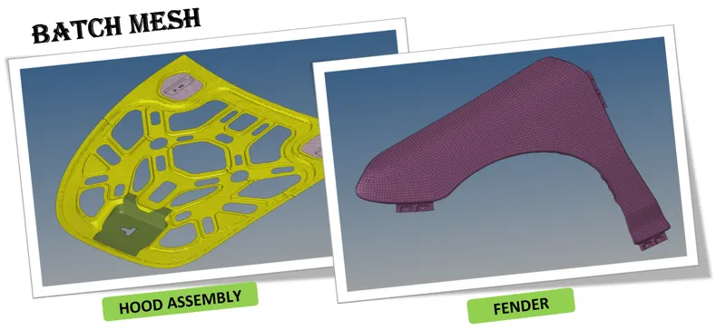
Figure 2. Batch Mesh
Step 3:
- To Cross check the mid surface, if there is any collapsed mid and meshes have to work on it manually.
- To eliminate the failed quality element.
- To eliminate more tria concentration.
ASSIGNING THE NON-LINEAR MATERIAL PROPERTY FOR RADIOSS PROFILE
Step 1: Create Material -
- Here the material created was steel and the card image for non-linear material is M2_PLAS_JOHNS_ZERIL
- The value of Initial density, Youngs modulus, poissons ratio, Yield stress, Hardening parameter, hardening exponent, Failure plastic strain, Maxium strees has been entered.
- The material tab has been shown in the below figure,
Step 2: Create Property -
- Here I have created two different property as Inner & outer panel thickness are 0.75mm & the thickness of Latch & Hinges are 1.2mm
- Shell thickness, No. of integration points through thickness, etc. has been given as shown in the below figure.
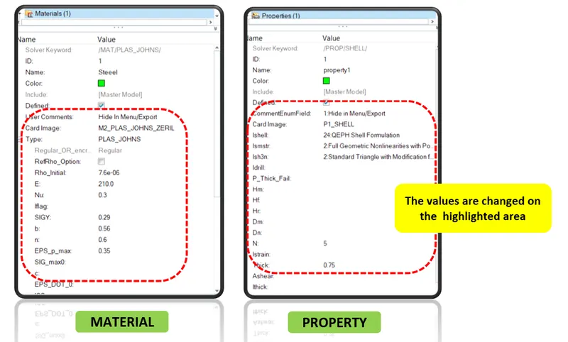
Figure 3. Material & Property Tab
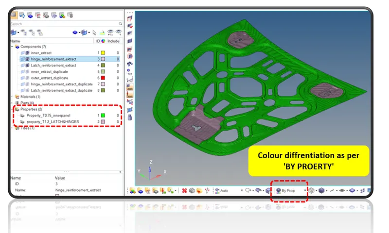
Figure 4. Colour differentiation 'BY PROPERTY'
Step 3: Assigning the created property & material to the respective components -
- Here the created property & material has been assigned to the respective components.
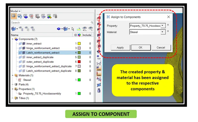
Figure 5. Assign to component
COMPARISON BETWEEN TRADITIONAL Vs BATCH MESH
- Here the hood inner panel is compared between batch mesh and Traditional automesh.
- By refering the below figure, We can find the difference between the Qualiy of the mesh, Mesh flow, Capturing the feature element,etc.
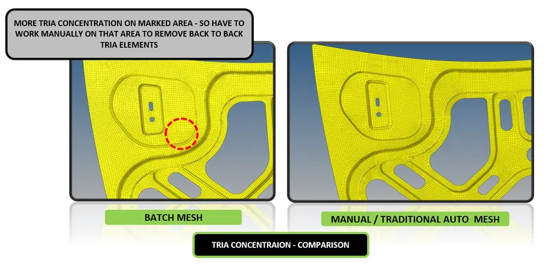
Figure 6. COMPARISON - BATCH MESH Vs TRADITIONAL AUTO MESH (Tria Concentration)
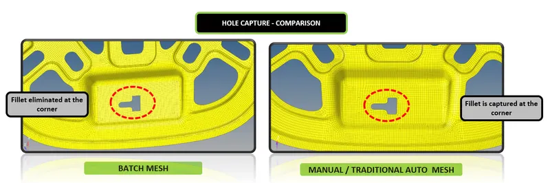
Figure 7. COMPARISON - BATCH MESH Vs TRADITIONAL AUTO MESH (Hole Capture)
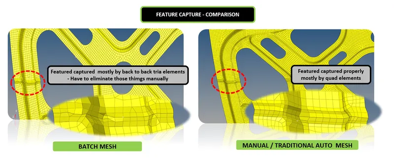
Figure 8. COMPARISON - BATCH MESH Vs TRADITIONAL AUTO MESH (Feature Capture)
CONCLUSION
Hence the Batch-meshing on the given components (Fender & Hood assembly - BIW component) with the given criteria has performed sucessfully and also the non-linear material property Steel for Radioss profile as assigned sucessfully to the components as per objective. Also the batch mesh & Traditional automesh has been compared by attatching some figures.
Figure 9. BATCH MESH
LEARNING OUTCOMES
At the end of this challenge, I can able to
Identify the suitable methods of mid surface extraction & mesh generation for a given component by considering the project time, Component complexity, etc