Otto-cycle Based Engine Kinematics
AIM: To write a MATLAB program to plot p-v diagram and determine the thermal efficiency of the engine.
OBJECTIVE :
- Understand the different processes of otto_cycle
- Understand how the work is done between gas and piston during each process
- Understand the assumptions mabe between the reallity and ideal ottto-cycle
- Understand the behaviour or nature of the curve during each process
- Plot the pressure and volume characteristics (P-V diagram)
- find the thermal efficiency of the engine
INPUTS :
- gamma = adiabatic index
- stoke = stroke length of the connecting rod
- bore = bore diameter of the cylinder
- con_rod = length of the connecting rod
- cr = compression ratio
- v_swept = swept volume of the cylinder
- v_clearance = clearance volume of the cylinder
- theta = crank angle
- v = volume of the cylinder
- e = thermal efficiency of the engine
- p1,v1,t1 = corresponding pressure,volume and temperature at point 1
- p2,v2,t2 = corresponding pressure,volume and temperature at point 2
- p3,v3,t3 = corresponding pressure,volume and temperature at point 3
- p4,v4,t4 = corresponding pressure,volume and temperature at point 4
EQUATIONS USD :
- v_swept = (pi/4)*bore^2*stroke
- v_clearance = v_swept/(cr-1)
- constant_c = p*v^gamma
- p*v = constant_c*t
- a = stroke/2
- R = con_rod/a
- v/v_c = (1 + 0.5*(cr-1)*(R + 1 - cos(theta) -( R^2 -sin(theta))^0.5))
- e = 1- 1/[cr^(gamma-1)]
THEORY:
An Otto cycle is an idealized thermodynamic cycle that describes the functioning of a typical spark ignition piston engine. The Otto cycle is a description of what happens to a mass of gas as it is subjected to changes of pressure, temperature, volume, addition of heat, and removal of heat through the following four internally reversible processes:
- Isentropic compression
- Constant-volume heat addition
- Isentropic expannsion
- Constant -volume heat rejection
DETAILS :
Programming language used : MATLAB
Concept used: Gas laws, engine kinematics
ASUMPTIONS :
- It is assumed that all the processes are internally reversible
- The working fluid is air, which continuously circulates in a closed loop (cycle).
- Air is considered as ideal gas.
- Combustion process is modeled by a heat-addition process from an external
source. - The exhaust process is modeled by a heat-rejection process that restores the
working fluid (air) at its initial state. - It is assumed that there will be no inefficiency during isentropic compression and expansion
PROGRAM AND STEPWISE EXPLANATION :
This program comprises of two sample code. The first code constutes the main part of the program and the second one is the definition of a function called "engine _inematics" .
MAIN PROGRAM
%This program aims to
%plot the p-v diagram;
%calculate the thermal efficiency of the engine for the given data
clear all
close all
clc

%Inputs
gamma = 1.4  %gamma is the adiabatic index
t3 = 2300    % t3 is the temperature at which the combustion takes place

%State variables
p1 = 101325         %p1 represents the atmospheric pressure
t1 = 500             %t1 is thne initial tempereature

% Engine geometric parameters
bore = 0.1;             %diameter of the cylinder
stroke = 0.1 ;          %Stroke-length of cylinder
con_rod = 0.15;         %length of the connwecting-rod
cr = 12;                %Compression ratio0p

%Calculating the swept volume and the clearance volume

v_swept = (pi/4)*bore^2*stroke;
v_clearance = v_swept/(cr-1);

v1 = v_swept + v_clearance
v2 = v_clearance

% State variables aat state point 2
% p2v2^gamma = p1v1^gamma
% p2 = p1*(v1/v2)^gamma = p1*cr^gamma
p2 = p1*cr^gamma;
%p1v1/t1 =p2v2/t2| t2 = p2*v2**t1/(p1*v1)
t2 = p2*v2*t1/(p1*v1)

constant_c = p1*v1^gamma;
V_compression = engine_kinematics(bore,stroke,con_rod,cr,180,0)
P_compression = constant_c./V_compression.^gamma;
% State variable at state point 3
v3 = v2

% p3v3/t3 = p2v2/t2 | p3 = p2*t3/t2

p3 = p2*t3/t2

constant_c = p3*v3^gamma;
V_expansion = engine_kinematics(bore,stroke,con_rod,cr,0,180)
P_expansion = constant_c./V_expansion.^gamma;

% State variable at state point 4
v4 = v1

% p3v3^gamma = p4v4^gamma | p4 = p3(v3/v4)^gamma
p4 = p3*(v3/v4)^gamma

%Calculation of the thermal efficiency of the engine| e = 1- 1/cr^(gamma-1)
disp('thermal efficiency')
e = 1- 1/[cr^(gamma-1)]

% All these commands enable us to plot p-v digram
figure(1)
hold on
plot(v1,p1,'*','color','r')
plot(V_compression,P_compression,'color','b')
plot(v2,p2,'*','color','r')
plot(v3,p3,'*','color','r')
plot(V_expansion,P_expansion,'color','b')
plot(v4,p4,'*','color','r')
plot([v1 v4],[p1 p4],'color','b')
plot([v2 v3],[p2 p3],'color','b')
xlabel('Volume in m^3')
ylabel('Pressure in  Pa')
title('P-V Diagram of Otto-cycle engine')
PROGRAM FUNTION
% This function aims to calculate the volume and gve the real nature of the
% curve during the isentropijc compressoion and expansion

function [v] = engine_kinematics(bore, stroke,con_rod,cr,start_crank,end_crank)


a = stroke/2;
R = con_rod/a;

v_s = pi/4*bore^2*stroke;
v_c = v_s/(cr-1);


theta = linspace(start_crank,end_crank,100);
term1 = 0.5*(cr-1);
term2 = R+1-cosd(theta);
term3 = (R^2 - sind(theta).^2).^0.5;

v = (1+term1*(term2 - term3)).*v_c;

end
OUTPUT:
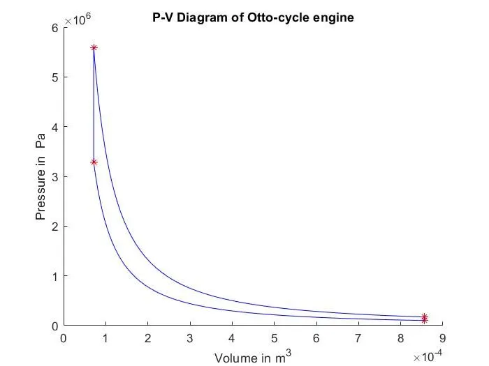

ERRORS OR PROBLEMS FACED WHILE PROGRAMMING :
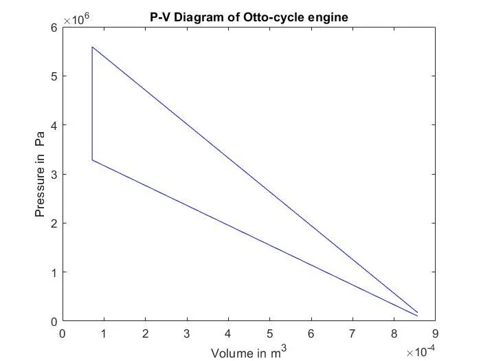
- while ploting the p-v diagram, if we use the single plot command then the following curve is obtained which is not the correct characteristics of the engine kinematics.
plot([v1 v2 v3 v4],[p1 p2 p3 p4],'color','b')
xlabel('Volume in m^3')
ylabel('Pressure in Pa')
title('P-V Diagram of Otto-cycle engine')
- Unbalanced parenthesis or brackets while writing mathematic expressions
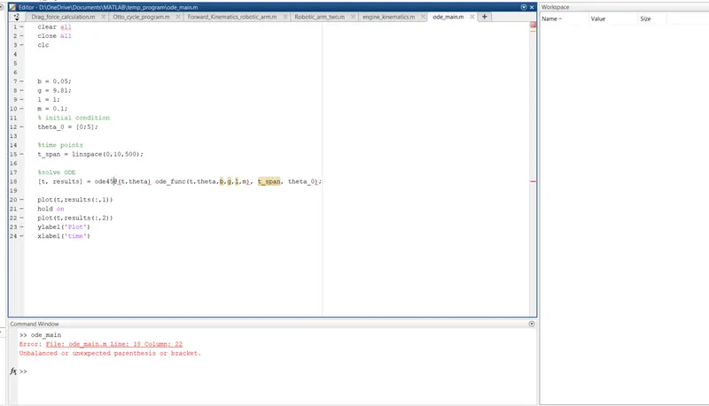
As solution, we have to check that all the parenthesis in a mathematic expression are balanced
CONCLUSION:
Hence we are able to understand the processes of otto_cycle, how work is done during each process and we can now discuss the assumptions made easily and explain exactly how the volume behaves during isentropic compression and expansion.
Furthermore, we plot the p-v diagram and we calculate the thermal efficiency of the engine