Modularity For OHT vehicles
CATERPILLAR INDIA PVT LTD (CIPL), CHENNAI.
INTERN REPORT
ACKNOWLEDGEMENT
I am student of B.E. Automobile Engineering, MIT Campus, Anna University, Chennai solemnly express my sincere gratitude to CATERPILLAR INDIA Pvt Ltd for giving me this wonderful opportunity to gain profound knowledge about the production process of an Off-Highway Truck.
I am highly indebted to my Corporate Mentor Mr. B. NANDHA KUMAR and Mr. S. VINOD BABU.
I also wish to express my hearty thanks to Mr. V. PRASANA, Human Resources Administrator for giving us the opportunity to work in CATERPILLAR INDIA PRIVATE LIMITED, THIRUVALLUR.
I wish to thank all the engineering employees and the operators for spending their time in enriching my knowledge and the support they provided for my work.
UNDER THE GUIDANCE OF
Mr. B. NANDHAKUMAR & Mr. S. VINOD BABU,
SECTION MANAGER – OPERATION - OFF HIGHWAY TRUCK,
PRODUCTION DEPARTMENT,
CATERPILLAR INDIA PVT LTD,
THIRUVALLUR.
ABSTRACT
The aim of our project is to study line balancing and to perform modularity on OHT vehicles in main assembly line. The minor operations which are performed before the main assembly line processes can help to reduce the assembly time significantly. Modularity requires us to understand each minor process that is occurring at individual main assembly workstation and also sub assembly. To understand each minor process, we must go-through the present standard worksheet for each main assembly workstation. This will basically support us to complete all the possible operations that can be done outside the main assembly line and then link those pre-assembled parts with the remaining operations occurring in the main assembly line. Modularity will help to optimize, reduce the assembly duration and make the assembly process of the OHT more efficient.
TABLE OF CONTENTS
CHAPTER
ACKNOWLEDGMENT
ABSTRACT
LIST OF FIGURES
ABBREVIATIONS
- INTRODUCTION
- COMPANY PROFILE
- VISION
- MISSION
- STRATEGY
- LIST OF MACHINARIES
- FACILITIES
- OHT DIVISION
- APPLICATIONS OF CAT VEHICLES
- LEAN MANUFACTURING
- LINE BALANCING
- DEFINITION
- CAPACITY PLANNING TERMS
- CYCLE TIME
- AVAILABLE TIME
- TAKT TIME
- WORK CONTENT TIME
- MANUFACTURING THROUGHPUT TIME
- BOTTLENECK TIME
- LOAD FACTOR
- EFFICIENCY
- UTILIZATION
- DETERMINE PHYSICAL LAYOUT
- TYPES OF CELL WORK FLOW
- ELEMENTS REQUIRED TO BALANCE A LINE
- KILBRIDGE AND WESTER COLUMN METHOD
- STEPS FOR LINE BALANCING
- MODULARITY OF OHT
- 3.1 DEFINITION
- 3.2 APPROACHES FOR MODULARITY
- 3.3 SCOPE FOR MODULARITY IN OHT ASSEMBLY
- 3.4 MODULARITY BENEFITS
- INFERENCE
- 4.1 LEARNING
- 4.2 FINDINGS AND SUGGESTIONS
- CONCLUSION
ABBREVIATIONS
|
OHT |
Off Highway Trucks |
|
CPS |
Caterpillar Production System |
|
ASSY |
Assembly |
|
LPT |
Lower Power Train |
|
SWS |
Standard Work Sheet |
1. INTRODUCTION
1.1 COMPANY PROFILE
Caterpillar is the world's leading manufacturer of construction and mining equipment, diesel and natural gas engines, industrial gas turbines. It ranks number one company in its field. Caterpillar Inc., is an American corporation which designs, develops, engineers, manufactures, markets and sells machinery, engines, financial products and insurance to customers via a worldwide dealer network.
The Company then organized itself into a Delaware corporation by the name Caterpillar Inc. With more than US$89 billion in assets, Caterpillar was ranked number one in its industry and number 44 overall in the 2009 Fortune 500. In 2018 Caterpillar was ranked #65 on the Fortune 500 list and #194 on the Global Fortune 500 list.
Caterpillar has been active in India since the 1930s. Caterpillar India Private Limited (CIPL)- Tiruvallur Plant is an owned subsidiary of Caterpillar Inc., formed after the acquisition of the earthmoving equipment division of Hindustan Motors by Caterpillar in February 2001, for an estimated US$ 71 million.
1.2 VISION
vision is a world in which all people’s basic needs – such as shelter, clean water, sanitation, food and reliable power – are fulfilled in an environmentally sustainable way and a company that improves the quality of the environment and the communities where we live and work.
1.3 MISSION
Mission is to enable economic growth through infrastructure and energy development, and to provide solutions that support communities and protect the planet.
1.4 STRATEGY
Our enterprise strategy focusses on solutions to help our customers built a better world and allows us to deliver profitable growth for our shareholders.
We are committed to understanding the needs of our customers, and together with our partners, delivering industry-leading products and services that are largely focussed in these areas:
- Building upon our core competencies of operational excellence-safety, quality, lean and competitive cost discipline- to increase our advantage.
- Expanding our offerings to enable customer success through integrated and differentiated solutions.
- Growing our reliance on services with a focus on digital-enabled solutions and aftermarket to increase customer loyalty and further strengthen our relationships with our customers.
1.5 LIST OF MACHINARIES
Caterpillar's line of machines ranges from tracked tractors to hydraulic excavators, backhoe loaders, motor graders, off-highway trucks, wheel loaders, agricultural tractors and locomotives. Caterpillar machinery is used in the construction, road-building, mining, forestry, energy, transportation and material-handling industries.
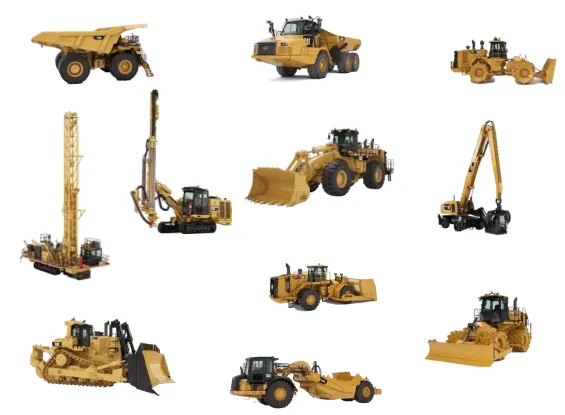
Figure 1.1 Caterpillar Product Range
1.6 FACILITIES
CIPL is functioning as two facilities
One facility takes cares of MH&U- Material Handling and Underground division which manufactures the following products:
- OHT-Off Highway Trucks
- LPT- Lower power train
- HEX-Hydraulic excavators
Second facility takes care of BCP- Building Construction Products where the following products are being manufactured:
- Backhoe Loaders
- Skid steer Loader
1.7 OHT DIVISION
In OHT there are four types of models currently being manufactured. They are
- 770G
- 772G
- 773E
- 777E
1.8 APPLICATIONS OF CAT VEHICLE
MINING AND QUARRY
Caterpillar manufactures 40,50,60 and 100-ton off highway trucks (OHT) in India for the domestic and export markets.
POWER GENERATION
Caterpillar offers a range of prime power and standby options to meet the varying needs of their customers. Given below are some examples of Caterpillar's power applications:
- Hindustan Construction Company Ltd. (HCC) uses Cat® Power in its 'Cold Desert' zone Nimoo-Bagzoo and Chuktak sites in Kargil area of Jammu & Kashmir.
- Oil & Natural Gas Corporation Limited (ONGC) is replacing all its existing engines with more than 170 Cat 3512B engines over the next 3 years.
- The Indian Navy, Coast Guard and Customs patrol the 7,000 kilometres of India's coastline with ships running on Cat power.
- ABG Shipyard, India's largest private ship builder ordered 20 Caterpillar 3516B HD Petroleum Power Modules.
CONSTRUCTION
Cat machines are working around the clock in the construction of the 2000 MW Hydroelectric Power Project at Subansri, Arunachal Pradesh, which includes digging and moving 1.14 million m3 of soil, civil works for diversion tunnels, coffer dams and concrete gravity dams, etc.
ROAD WORKS
Whether it is in the Golden Quadrilateral or the national road corridors, Cat machines are deployed at every stage of the road construction from embankment to road finishing.
PETROLEUM SECTOR
Cat reciprocating engines and Solar Turbines, enable gas compression for key customers including Reliance, ONGC, British Gas, CAIRN India and OIL India.
RAIL SECTOR
Electro-Motive Diesel Inc. (EMD) is the world's leading manufacturer of Diesel Locomotives with a turnover of $1.8 billion. Currently EMD fully supports the ramp up of production at DLW to manufacture up to 200 locomotives per year. The Indian Railways deems locomotives powered by EMD technology and equipment to be highly reliable with an impressive availability rate of 91 - 95 percent.
1.9 LEAN MANUFACTURING
Lean manufacturing or lean production, is a systemic method for the elimination of waste within a manufacturing process. Lean also considers waste created through overburden and waste created through unevenness in workloads.
CATERPILLAR PRODUCTION SYSTEM
New technologies, techniques and processes are constantly being developed and caterpillar is a forefront of these continuous improvement efforts.
The CPS focuses on 3 types of processes:
- CORE includes the fundamental factory floor operational processes that encompass all activities from demand planning to delivery of finished products.
- GOVERNING is related to governance activities associated with tracking and measuring safety, quality and six sigma benefits.
- ENABLING processes are related to information management, people, culture and value stream transformations.
The CPS strategy is process focussed i.e., processes will be treated the same way Caterpillar has treated products in the past. For instance, key processes will have process managers that are comparable to product managers. They will be accountable for developing process strategies, creating and managing multi-generational process plans and accessing process improvements with six sigma based metrics.
2.LINE BALANCING
2.1 DEFINITION
A production line is said to be in balance when every worker’s task takes the same amount of time. Line balancing is a manufacturing-engineering function in which whole collection of production-line tasks are divided into equal portions. Well-balanced lines avoid labor idealness and improve productivity.
Line-balancing strategy is to make production lines flexible enough to absorb external and internal irregularities. There are two types of line balancing, which we have explained as –
- Static Balance – Refers to long-term differences in capacity over a period of several hours or longer. Static imbalance results in underutilization of workstations, machines and people.
- Dynamic Balance – Refers to short-term differences in capacity, like, over a period of minutes, hours at most. Dynamic imbalance arises from product mix changes and variations in work time unrelated to product mix
2.2 CAPACITY PLANNING TERMS
2.2.1 CYCLE TIME
- For any production operation, cycle time is the total time from the beginning to the end of the process.
- Cycle time includes process time, during which a unit is acted up on to bring it closer to the output and delay time during which a unit of work is waiting to take the next action.
- In simple its period required to complete one cycle of operation from start to end.
2.2.2 AVAILABLE TIME
Time available to the operator to perform his task.
2.2.3 TAKT TIME
Takt time is the average time between the start of production of one unit and the start of production of the next unit, when these production starts are set to match the rate of customer demand. Assuming a product is made one unit at a time at a constant rate during the net available work time, the takt time is the amount of time that must elapse between two consecutive unit completions to meet the demand. Takt time can be first determined with the formula,
Where
T = Takt time (work between two consecutive units)
Ta = Net time available to work (work time per period)
D = Demand (customer demand)
Net available time is the amount of time available for work to be done. This excludes break times and any expected stoppage time. Also, takt time can be adjusted according to requirements within the company.
2.2.4 WORK CONTENT TIME
An assembled product requires certain amount of time to build, called the work content time. This is the total time of all work elements that must be performed on the line to make one unit.
2.2.5 MANUFACTURING THROUHPUT TIME
Manufacturing throughput time is the amount of time required for a product to pass through a manufacturing process, thereby being converted from raw materials into finished goods. The content also applies to the processing of raw materials into a component or sub-assembly.
The concept of manufacturing throughput time is primarily oriented toward the reduction of time required by the manufacturing process, so that you can increase the amount of throughput flowing through the system and thereby increase the profitability.
2.2.6 BOTTLENECK TIME
In flow line mass production, the operation of the production line is complicated by interdependencies of the work stations on the line and one another complication is impossible to divide the work content equally among all the work stations on the line therefore one station ends up with longest operation time and this station sets u pace for the entire line and that station is the bottleneck station and the longest operation time is bottleneck time.
The bottleneck could be either because of man or machine in that work station.
2.2.7 LOAD FACTOR
In assembly line balancing the load factor is defined as the cycle time of the work station divided by the bottleneck time in the specific work area.
2.2.8 EFFICIENCY
E= output/input
It is the ratio of output to the input.
2.2.9 UTILIZATION
Utilization refers to the amount of output of a production facility relative to its capacity.
Utilization will be measured by percentage it can be for labor resources also.
2.3 DETERMINE PHYSICAL LAYOUT
- Place machine close together to minimize walking.
- Remove obstacles from walking paths.
- Eliminate surfaces where inventory can accumulate.
- Maintain consistent heights for work surfaces and point of use.
- Locate start and end of cell near each other
- Keep sides of machines open to allow transfers of parts.
- Use gravity to assist team member in moving materials.
- Keep hand tools close and oriented in direction they will be used.
- Use dedicated tools and combine tools where possible.
2.4. TYPES OF CELL WORK FLOW
- SPLIT THE WORK
- THE CIRCUIT
- REVERSE FLOW
- COMBINATIONS
- ONE- TEAM MEMBER PER STATION
2.5 ELEMENTS REQUIRED TO BALANCE A LINE
- Demand, available time, takt.
- Variable caused by product configuration.
- Operation sequence- dependent, independent process.
- Cycle time scientific, variation with actual time, process time, main time, machine time
- OEE & OPE information
- Physical layout
- Material movement
- Variation by customer
- Assumptions and constraints to ensure organizational fit
2.6 KILBRIDGE AND WESTER COLUMN METHOD
- It is a heuristic procedure which selects work elements for assignment to stations according to their position in the precedence diagram.
- This overcomes one of the difficulties with the largest candidate rule (LCR), with which elements at the end of the precedence diagram might be the first candidates to be considered, simply because their values are large.
Procedure:
Step 1. Construct the precedence diagram so those nodes representing work elements of identical precedence are arranged vertically in columns.
Step 2. List the elements in order of their columns, column I at the top of the list. If an element can be located in more than one column, list all columns by the element to show the transferability of the element.
Step 3. To assign elements to workstations, start with the column I elements. Continue the assignment procedure in order of column number until the cycle time is reached (Tc).
2.7 STEPS FOR LINE BALANCING
- Determine tasks involved in completing one unit.
- Estimate task times.
- Identify station wise work content.
- Arrive station wise manpower.
- Identify zone wise activities.
- Identify activities require crane.
- Identify tasks require >1 manpower.
- Revise the work content based on it.
- Determine order of tasks (independent/ dependent).
- Draw a sequence/precedence diagram.
- Calculate takt time
- Calculate minimum no of work stations.
- Selection of a heuristic method for assigning tasks to workstations.
- Form the nodal diagram.
- Gantt chart.
- Operator balance chart
- MODULARITY OF OHT
3.1 DEFINITION
The definition of modularity can vary from person to person. Many Scholars and practitioners alike have proposed many definitions of modularity. After analyzing the meanings of everyone’s definitions, the most prominent definitions are –
- Modularity: refers to the degree to which a system’s components can be separated and recombined.
- Modularity: a bundle of product characteristics rather than an individual feature, and different disciplines and viewpoints emphasize different elements of this bundle.
- Modularity: a particular pattern of relationships between elements in a set of parameters, tasks, or people; a nested hierarchical structure of interrelationships among the primary elements of the set.
3.2 APPROACHES OF MODULARITY
Putting together the various approaches to modularity that we identified in the interviews we came up with the following five-level classification:
- Traditional Layer Build (TLB)—This is not considered a module, but serves as the base to compare to. For several decades, TLB has been the paradigm by which vehicles were manufactured.With this method, the entire vehicle is created piece-by-piece, layer-by-layer throughout the design, development, and assembly processes.
- Assembly Module—This is the simplest and earliest form of module encountered. With the assembly module, OEMs keep the responsibility for concept creation and design engineering, while components are either made in-house or outsourced to suppliers. The OEMs simply outsource part of the assembly process from within their own plants and outsource it to the supplier plants.
- Mature Assembly Module—This approach goes one step beyond the Assembly Module in that the OEM is still responsible for the creation of the concept and controls the engineering. However, design engineering is often done with involvement (to varying degrees) of the supplier. In this approach, components are generally outsourced to various suppliers, often with direct control of the OEM, and assembly of the module is done at the supplier plant.
- Design Module—The modules in this category can be described as a collaborative effort between the OEM customer and the module supplier. Concept creation is shared between the OEM and supplier, design engineering is done by the supplier, components are outsourced to the supplier, and assembly of the module is done by the supplier. At the time of the interviews no supplier had a Design Module in production, but they were making progress in this direction, in some cases just starting a program based on Design Modules.
5) Integrated Design Module—These are rare or nonexistent in practice depending on how stringently defined, and it may be some time before it is realized in the global automotive industry. It is the most ambitious type of module from a design, performance, and production point of view.
3.3 SCOPE FOR MODULARITY IN OHT ASSEMBLY
After analyzing and understanding the entire assembly process of OHT by going through all the SWS of main assembly workstations, we can find out the process that can be done before we start the main assembly. For example, we can fill the required oils in the rear axle, differential and front axle before itself instead of filling the oils in the main assembly line which will help us to reduce the cycle time pertaining to that workstation. There are many other processes that can be done before the main assembly process which has been listed later on.
- BENEFITS OF MODULARITY
- The standardization of parts and modules that occur in mass customization yields higher product quality and is conducive for repetitive manufacturing at low cost.
- Another inherent benefit of mass customization includes the benefits of the build-to-order concept due to customer involvement, which minimizes finished goods inventories since customized products are not produced until customer orders arrive.
- Modularity could aid in increasing product variety as well as shorten delivery lead times.
- Modularity include bringing customer specifications into the product design and achieving mass production manufacturing efficiencies.
- INFERENCE
4.1 LEARNING
- Assembly process of OHT vehicles.
- Documentation works related to OHT assembly with special emphasis on SWS.
- Line balancing.
- Basics of modularity.
4.2 FINDINGS AND SUGGESTIONS
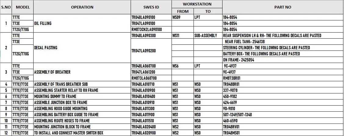
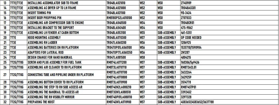

- If all the oil filling processes that are done to fill rear axle, differential and front axle and also the assembly of breather are done in LPT assembly instead of workstation 09, then it can help to reduce cycle time significantly.
- The most time consuming processes such as pasting decals, preparing and assembly of the battery box, assembling platform and all of its components, attaching ladder to the platform, preparing the hoist and assembling the RH side access AR are done in the Sub ASSY instead of the main ASSY line can aid in reduction of cycle time.
- All the minor processes that doesn’t require the support of crane ( weight less than 8KG), less number of operators and is possible to perform using torque wrench and battery gun can be done before lowering the frame in the pre workstation.
CONCLUSION:
Modularity and Line balancing can contribute a lot to pretty much every organization, regarding to manufacturing and production field of work. It’s a critical process that must be understood deeply by everyone in a leadership position, and the sooner your organization decides to start implementing modularity in its own assembly processes, the bigger benefits you’re going to see in the end. This can help to cut short the cycle time by a great margin.