Aim/Objective:
To simulate and evaluate a 25-story structure based on provided specifications, and to verify the parameters in accordance with IS 1893 regulations. Please ensure the response is in English.
Introduction:
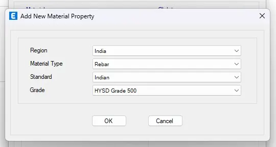
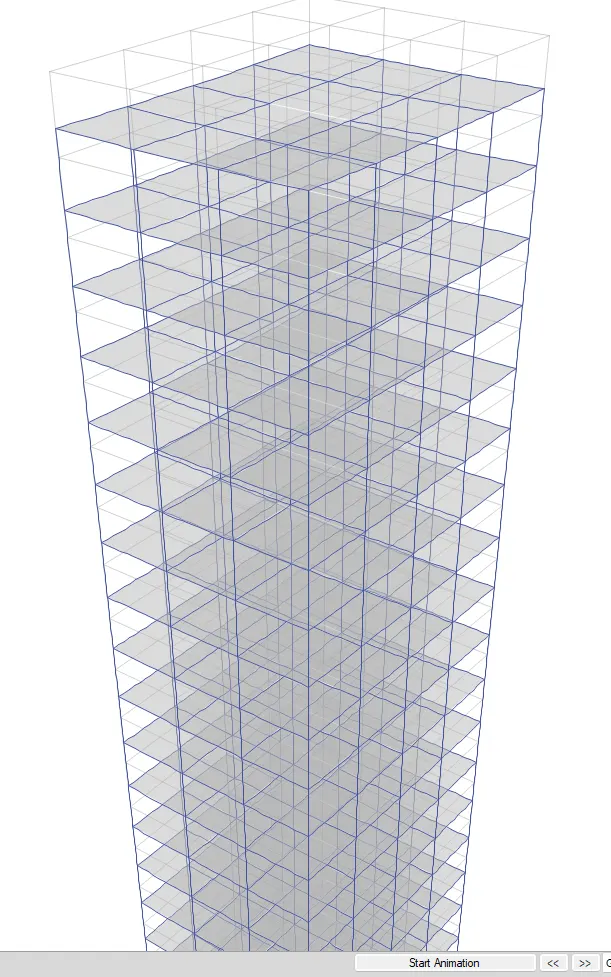
We're tasked with modeling and analyzing a 25-story building per given specs. Our goal is to verify parameters according to IS 1893, ensuring compliance. Using ETABS, we define materials, sections, and loads. The structure has 26 storeys, with plinth at 1.5m and subsequent floors at 3m each. Material properties: Concrete M30, steel: 415 for transverse, 500 for longitudinal. Columns are 800x800mm, slab thickness 150mm. A membrane property with a 150mm slab accounts for weights in analysis. Beams are drawn with quick draw tool. Pinned supports are placed at the base for stability. Load patterns (dead load, live load, brick load, earthquake loads) follow IS codes. Our aim is a safe, resilient 25-story building.
Steps/Procedure:
1. Launch the ETABS software.
2. Access the file menu and select the option to initiate a new model.
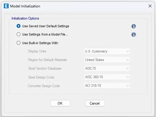
3. Upon selecting a new model, a dialog box for model initialization will emerge.
![]()
4. Click on the pre-set options and pick how you want things to be shown, like measurements and rules.
5. After starting the model, choose the grid and story settings from the box that pops up.
6. In this box, pick your own measurements for the grid and stories. This helps set things up the way you want.
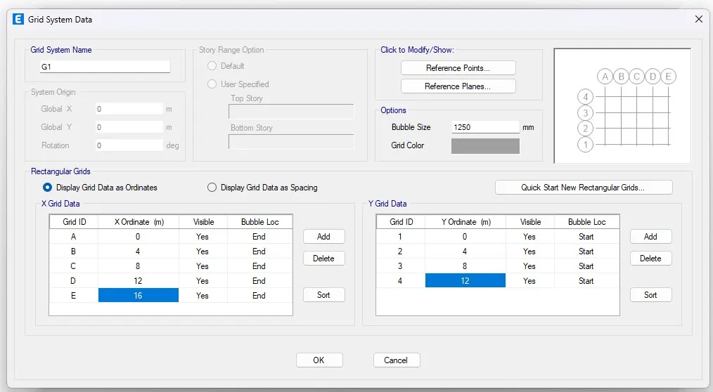
7. Put in the X grid information every 4 meters apart, and for the Y grid, do the same, also 4 meters apart.
8. Next, adjust the floors using your own measurements. There are a total of 26 floors: the first floor starts at 1.5 meters, and then there are 25 floors each with a height of 3 meters. The first floor is called the "master floor," and all the floors above it are named in the same way
![]()
< ></>
<> </>
<>>
<>>
<> </>
<>< alt>
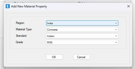
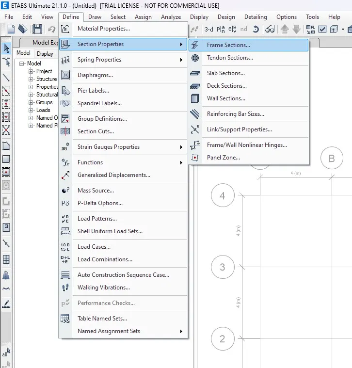
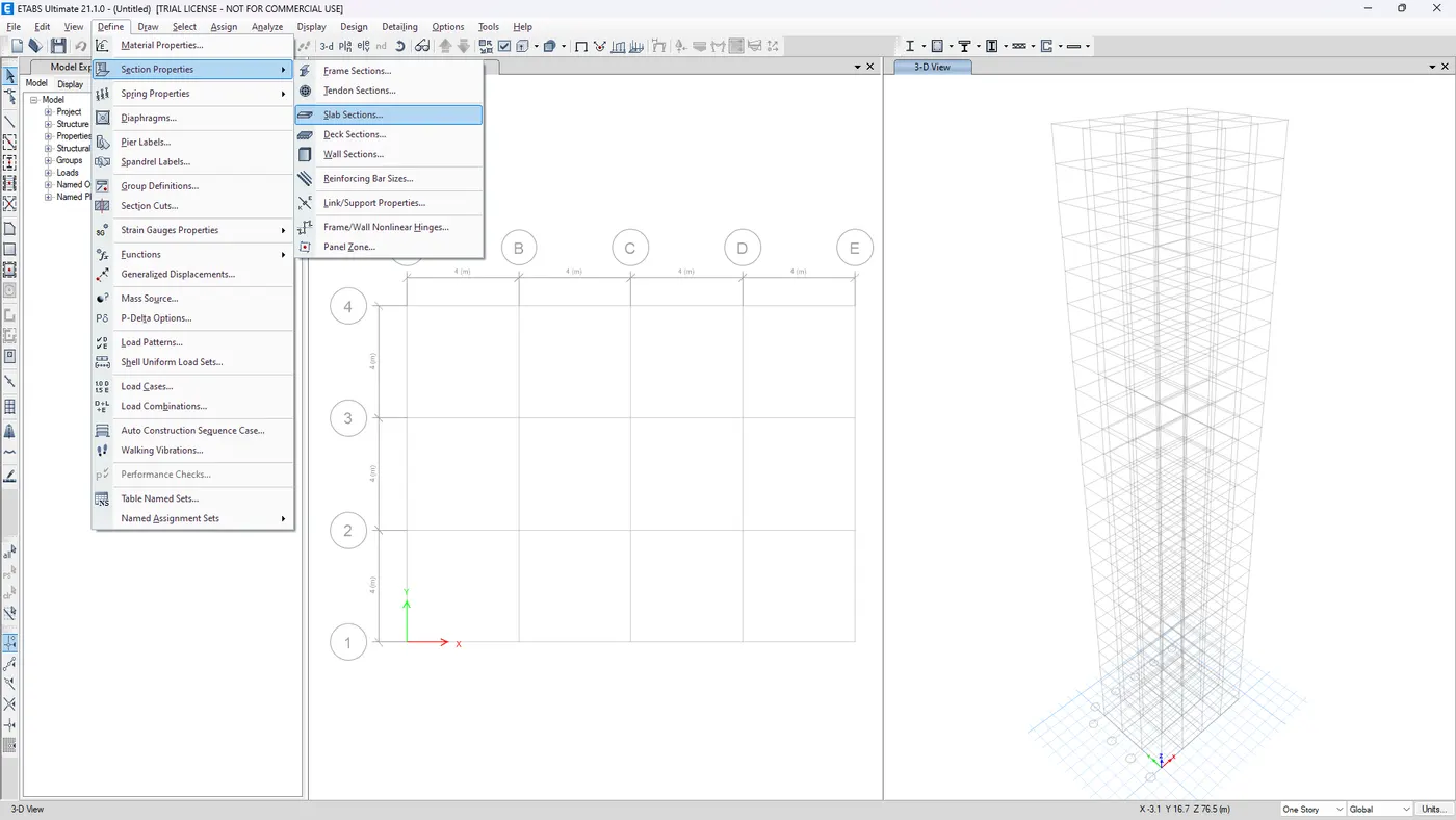
11. Navigate to the "Define" tab and choose "Section Properties".
Click on the frame section, then create a new property labeled as a beam, and input the dimensions as 300 by 400 millimeters.
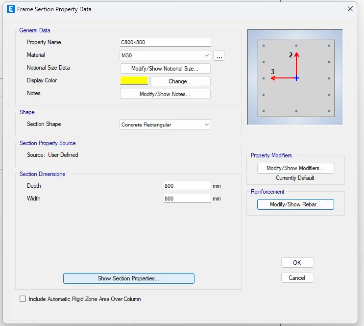
12. Once you're done defining the properties, set the dimensions for the columns as 800 by 800 millimeters, and for the slab thickness, specify it as 150 millimeters.
13. By applying the membrane property, a slab with a thickness of 150mm has been included in the list. This property ensures that only the weights of the slab and the floor are taken into account in the structural analysis. This means that no stiffness component from the flange is considered in the calculations.
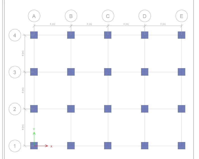
14. Using the quick draw tool, create a column with dimensions of 800 by 800 millimeters at the point where the horizontal and vertical grids intersect. Make sure to include beams and keep all stories active while drawing.
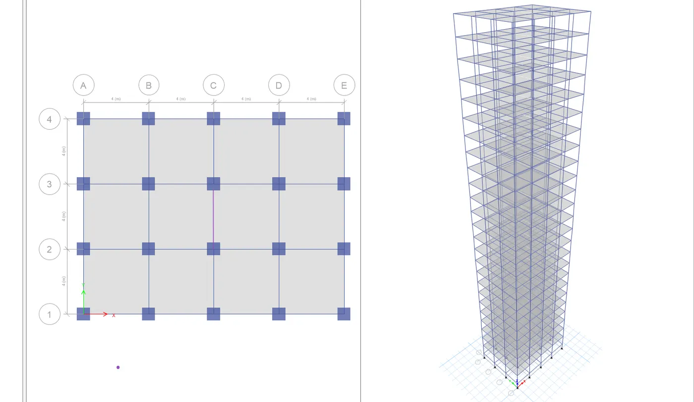
15. Draw beams using the quick draw beam tool, making sure to have all the stories active.
16. By utilizing the quick draw floors option, all the slabs have been modeled with the "similar stories" option enabled.
17. Go to the "Assign" tab and choose "Joint".
18. Select "Pinned Support" and then fix the pin supports at the base.
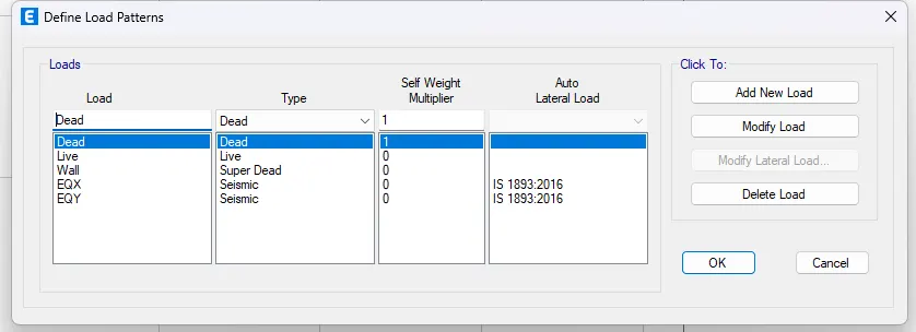
19.To define the load patterns, go to the "Define" tab and select "Load Patterns". Specify the following loads:
- Dead Load
- Live Load
- Brick Load
- Earthquake Load in the X direction (Positive X and Negative X)
- Earthquake Load in the Y direction (Positive Y and Negative Y)
20. Ensure that you mention the relevant IS codes for each load type.
21. Access "Modify Lateral Load", select the range from the base to the 25th storey, and input the following parameters:
- Seismic Zone Factor: 0.36
- Importance Factor: 1.25
- Time Period: 0.5 seconds
22. Apply the same settings for all earthquake loads.
23. Assign these loads and choose "similar stories". Go to the "Assign" tab, then select "Shell Load".
24. Click on "Live Load" and set the value to 3 kilonewtons per square meter.
25. Finally, click on "Apply".
26. For the roof, we will consider only 50% of the live load.
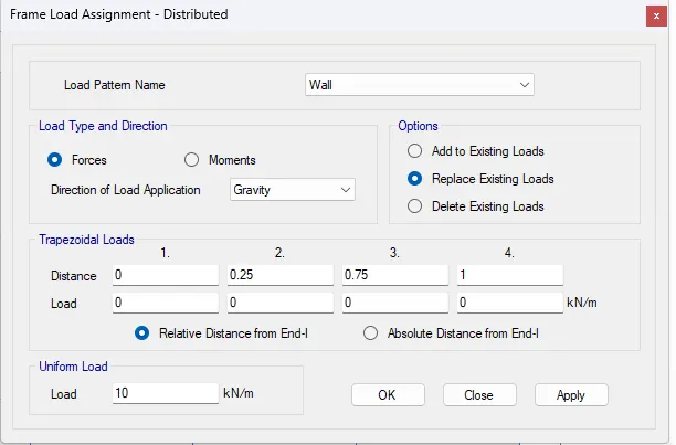
27. In the same manner, apply a live load of 10 kilonewtons per square meter to all the beams.
Follow these steps:
- Select all the beams by choosing the object type "beams".
- Go to the "Frame Load" section.
- Click on "Distributed Load" and input the value as 10 kilonewtons per square meter.
28. Head to the "Define" tab and select "Mass Source".
29. Adjust the settings in the mass source and check the necessary loads.
30. Then, include the load patterns and assign them to the model.
31.Define the load cases by following these steps:
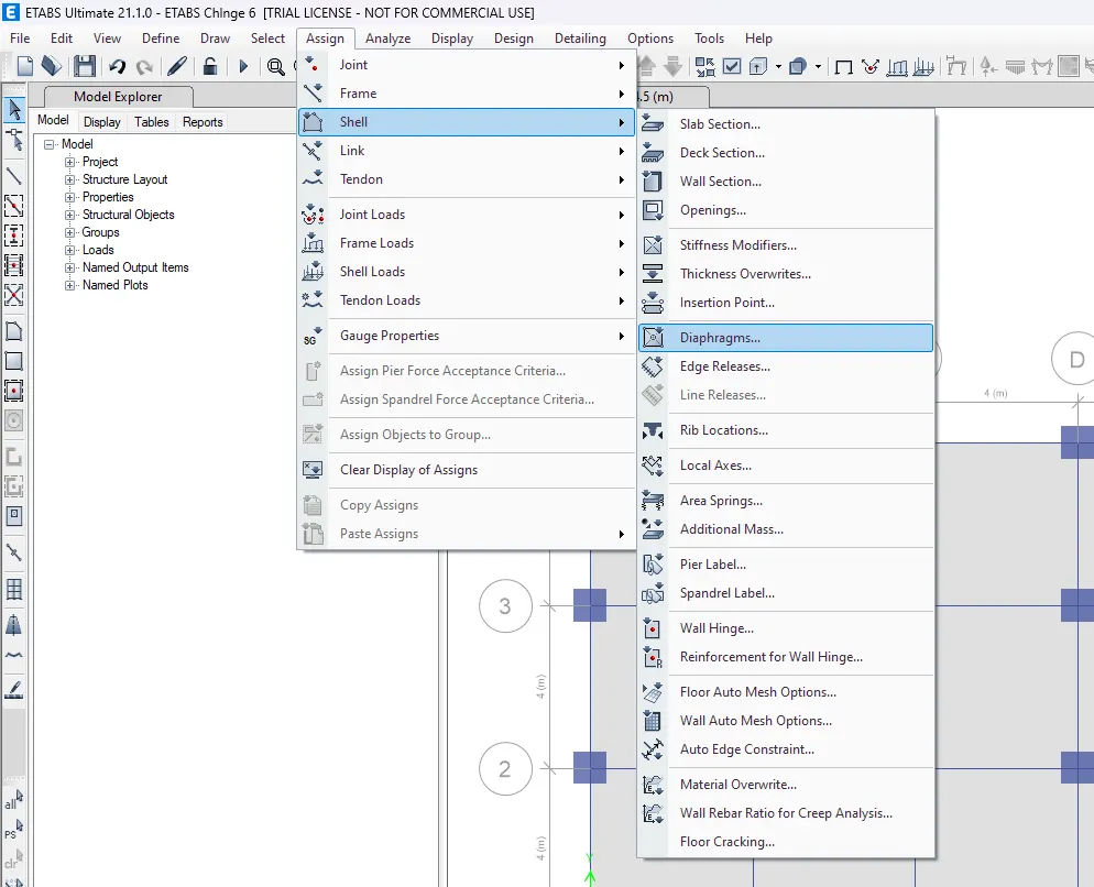
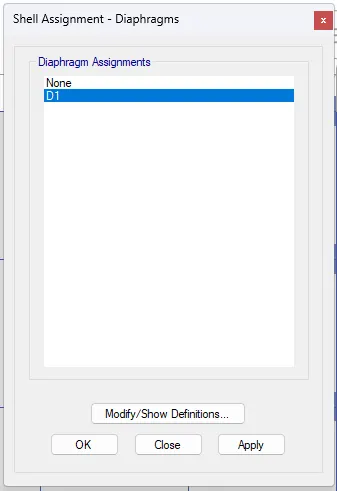
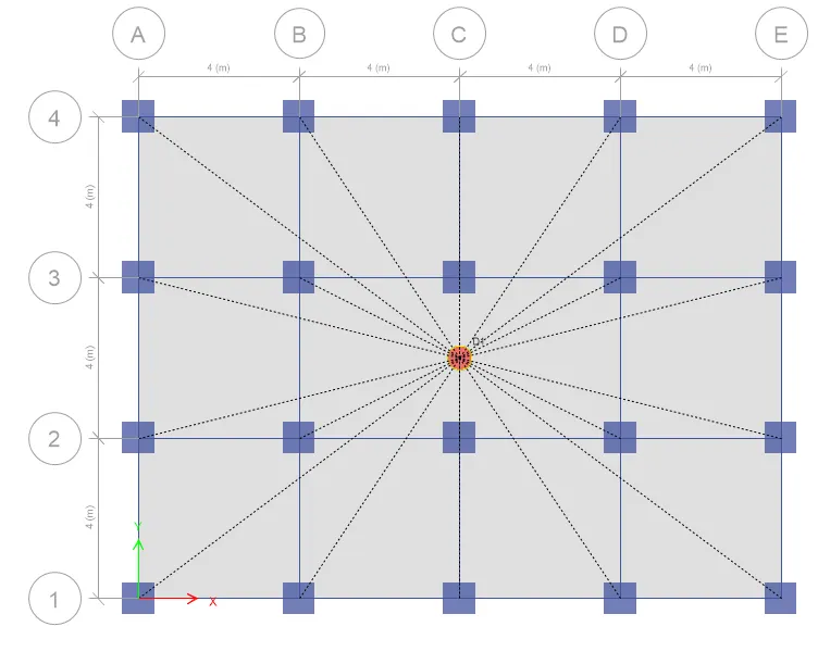
31. To create the diaphragm, navigate to the "Assign" tab, then select "Shell", and choose "Diaphragms".
32. Press "OK".
33. Analyze the model by selecting the "Analyze" option. Afterwards, click on "Check Model" to verify that the modeled structure is free of errors and warnings.
34. By initiating the analysis through "Analyze > Run Analysis," the model undergoes thorough examination. Deflection patterns as well as Bending Moment Diagrams (BMD) and Shear Force Diagrams (SFD) patterns are meticulously reviewed for consistency. This process reaffirms the reliability of the working model and the accuracy of its results.
Results:
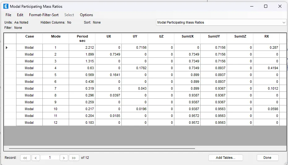
1. Next, navigate to "Display > Show Tables > Analysis Results > Structure Output > Modal Information > Modal Periods and Frequencies".
2. From the table, extract the time periods for the fundamental modes - 1Y direction and 1X direction. These values are as follows:
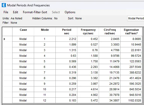
3. Tx1=2.212 secounds and Ty1=1.899 seconds
4. Proceed to "Display > Show Tables > Analysis Results > Structure Output > Modal Information > Modal Participation Mass Ratios".
5. In the table, identify the natural time period for mode-1 and the torsional Degree of Freedom (DOF).
The values are noted as follows:
- Natural Time Period for Mode-1> 2.212 seconds
- Natural Time Period for Mode-2> 1.899
- Torsional DOF Time Period> 1.315 seconds
6. Based on the results, it's evident that the torsional time period is less than two times the translational time period, as stipulated by IS 1893 provisions in Table 5.
7. Furthermore, we got more then 70% in first mode. This signifies that the initial three modes of seismic oscillation collectively contribute more than 65% of the total building weight, according to the ETABS analysis.
8. For the serviceability base shear case (EQX or EQY), the storey drift is tabulated using the following steps:
9. Go to "Display > Storey Response Plot".
10. With the load case set to EQY, switch to "Max Story Drift".
11. The maximum drift value recorded is 0.0033.
p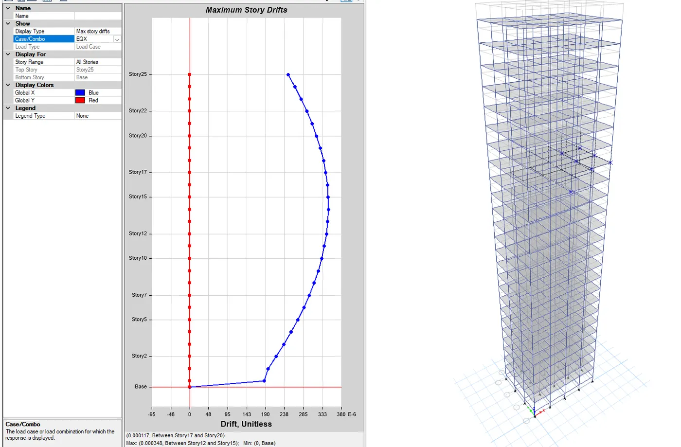
12. According to clause 7.11.1.1, the maximum allowable inter-storey drift is limited to 0.004 times the storey height. In our analysis, we have a recorded value of 0.0033, which falls comfortably within the specified code limits.
Conclusion:
The modeling and analysis in ETABS have been successfully completed. The obtained results are well within the specified ranges provided.