COMPARATIVE STUDY OF DIFFERENT STOREY BUILDINGS FOR SEISMIC FORCES
Introduction:
ETABS is a specialized engineering software designed for the comprehensive analysis and design of multi-story buildings. The acronym "ETABS" stands for "Extended Three-Dimensional Analysis of Building System."
Aim/Objective:
1. Utilize ETABS software to extract various seismic responses of a structure and manipulate specific properties.
2. Understand the elements that impact the dynamic characteristics of a building.
3. Comprehend the factors that affect the natural period of a building.
4. Gain insights into the factors influencing the mode shapes of oscillations.
> Now, let's discuss the provided data.
Procedure:
Steps to implement the provided data.
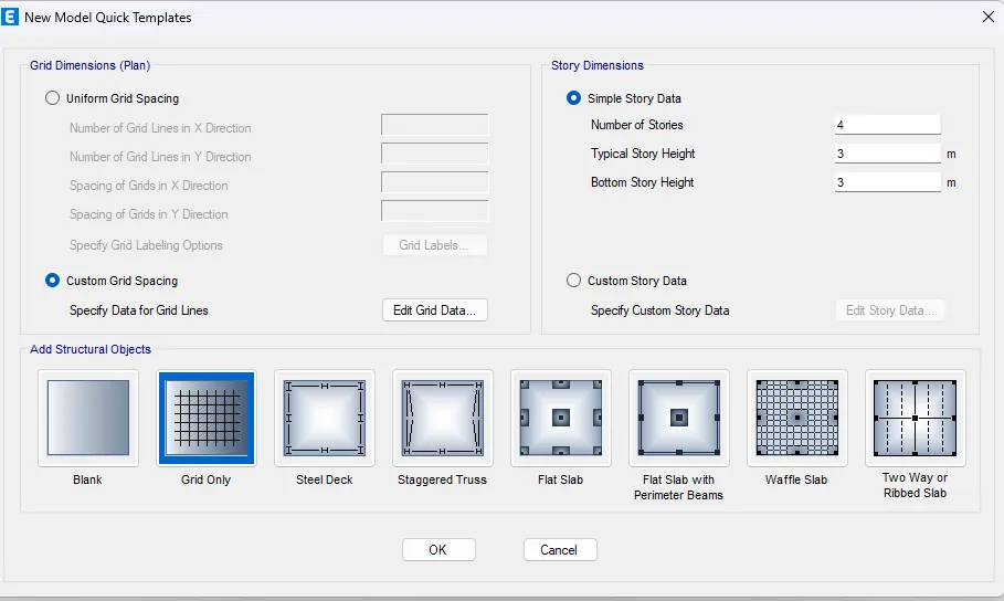
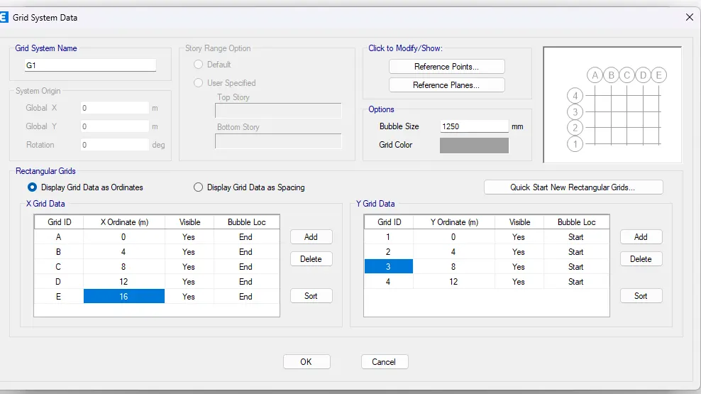
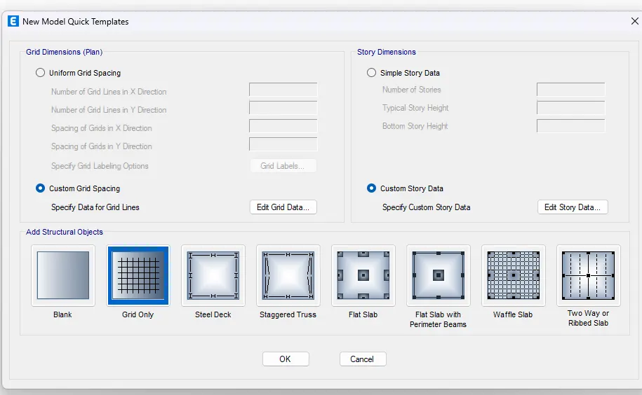
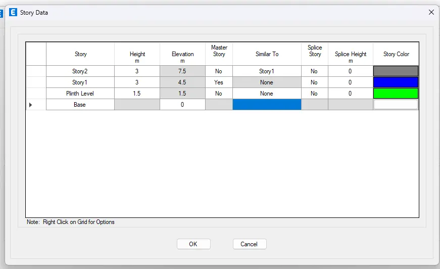
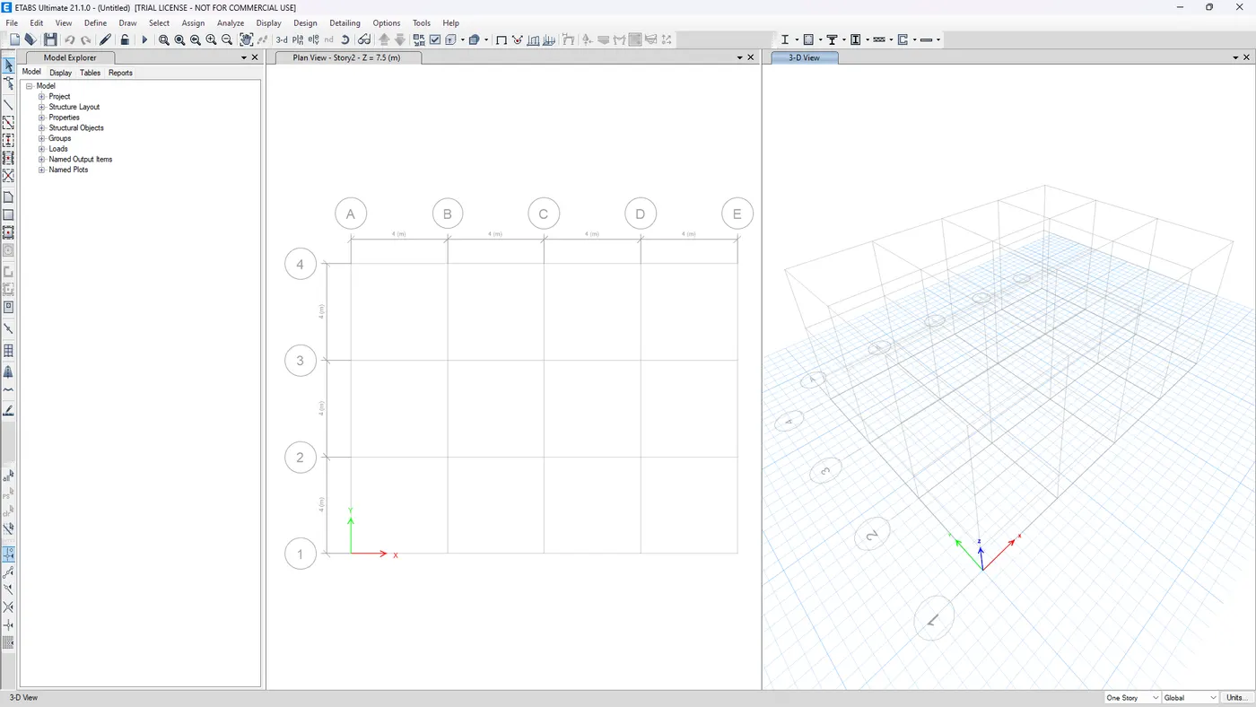
i. Click on "Define."
ii. Select "Material Properties."
iii. Choose "Add New Material."
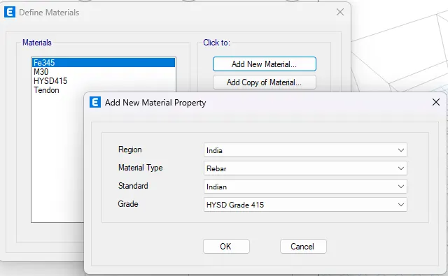
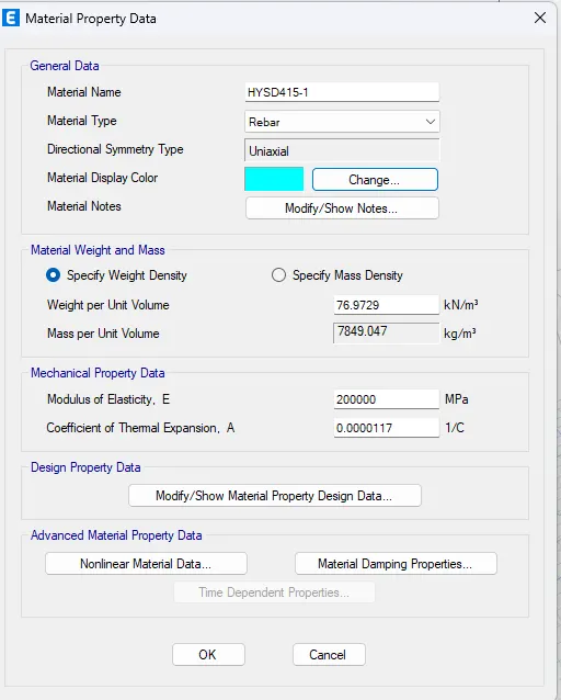
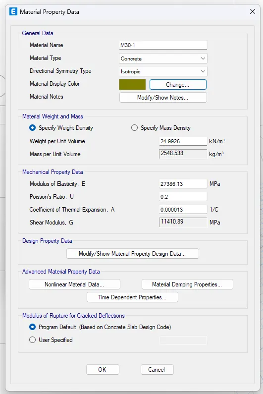
i. Click on "Define."
ii. Choose "Section Properties."
iii. Select "Frame Section."
iv. Opt for "Add New Property."
v. Specify the shape as a rectangle.
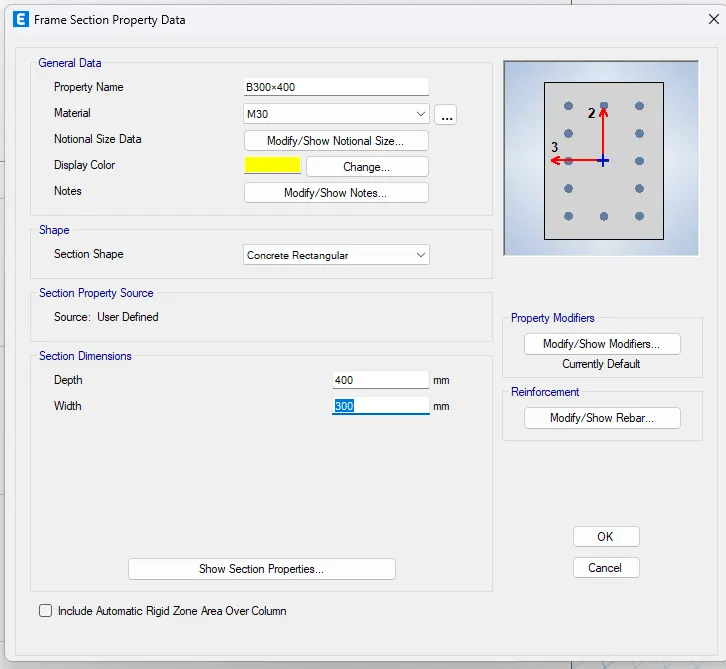
i. Add a beam with the size B300x400.
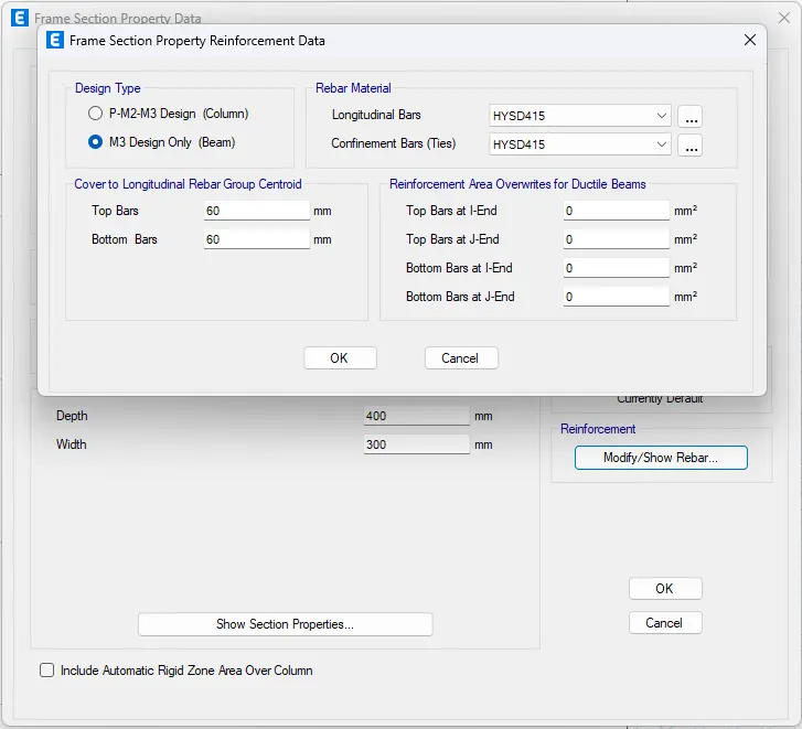
ii. To provide reinforcement details for the beam, click on the "Modify/Show Rebars" button. Input the following data.
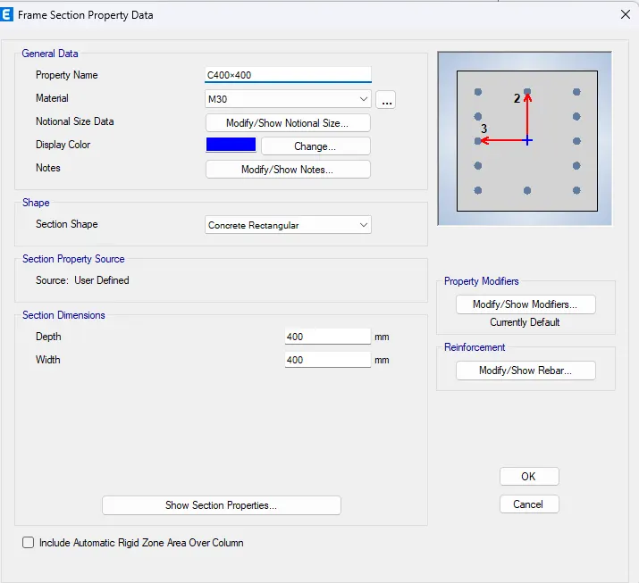
15. For columns, click on "Add New Property".
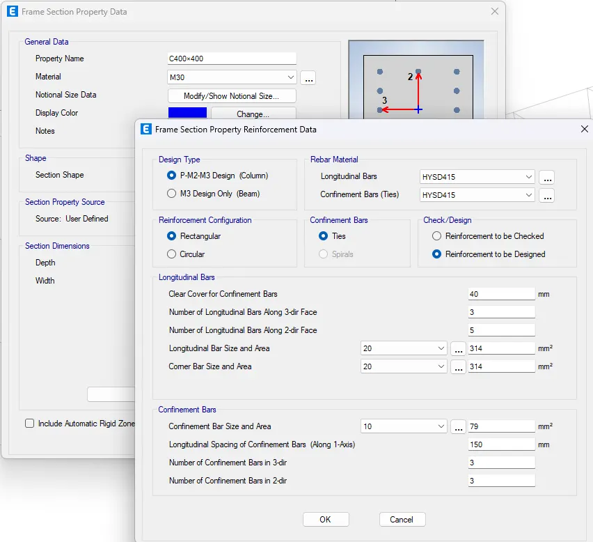
17. To provide reinforcement details for the column, click on the "Modify/Show Rebars" button and input the following data.
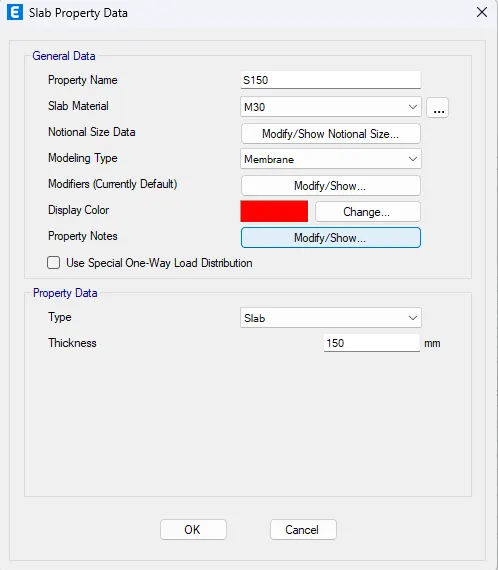
19. For slabs, navigate to "Define" -> "Section Property" -> "Slab Section" -> "Add New Property".
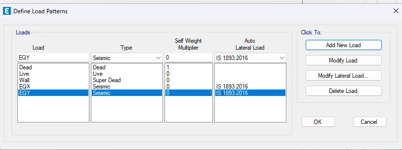
i. Click on "Add New Load" after entering the relevant data.
ii.Then, select "Modify Lateral Load" for both seismic types as specified.
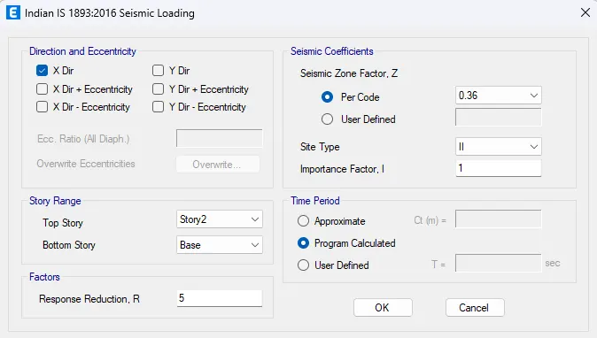
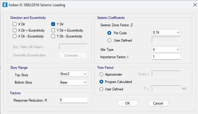
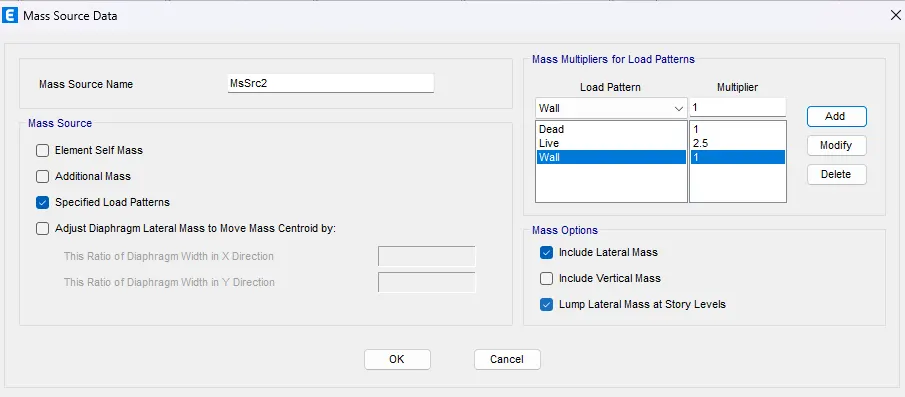
24. To define the mass source, go to "Define" -> "Mass Source" -> "Modify/Show Mass Source".
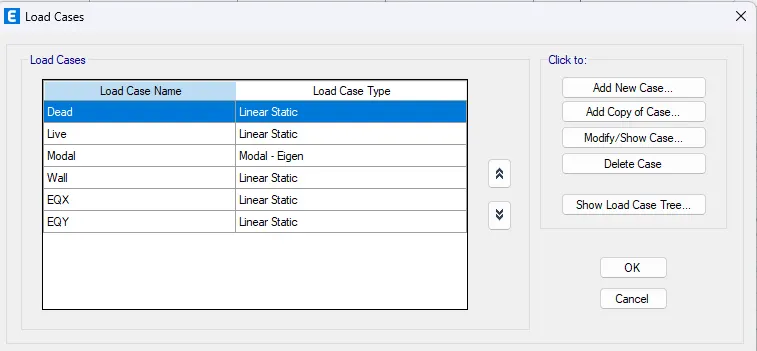
26. To review the load cases, navigate to "Define" -> "Load Cases".
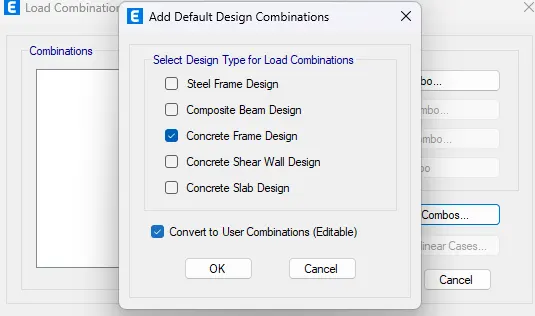
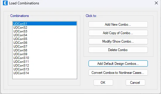
i. Go to "Define" -> "Load Combination".
ii. Select "Add Default Design Combination".
30. MODELLING
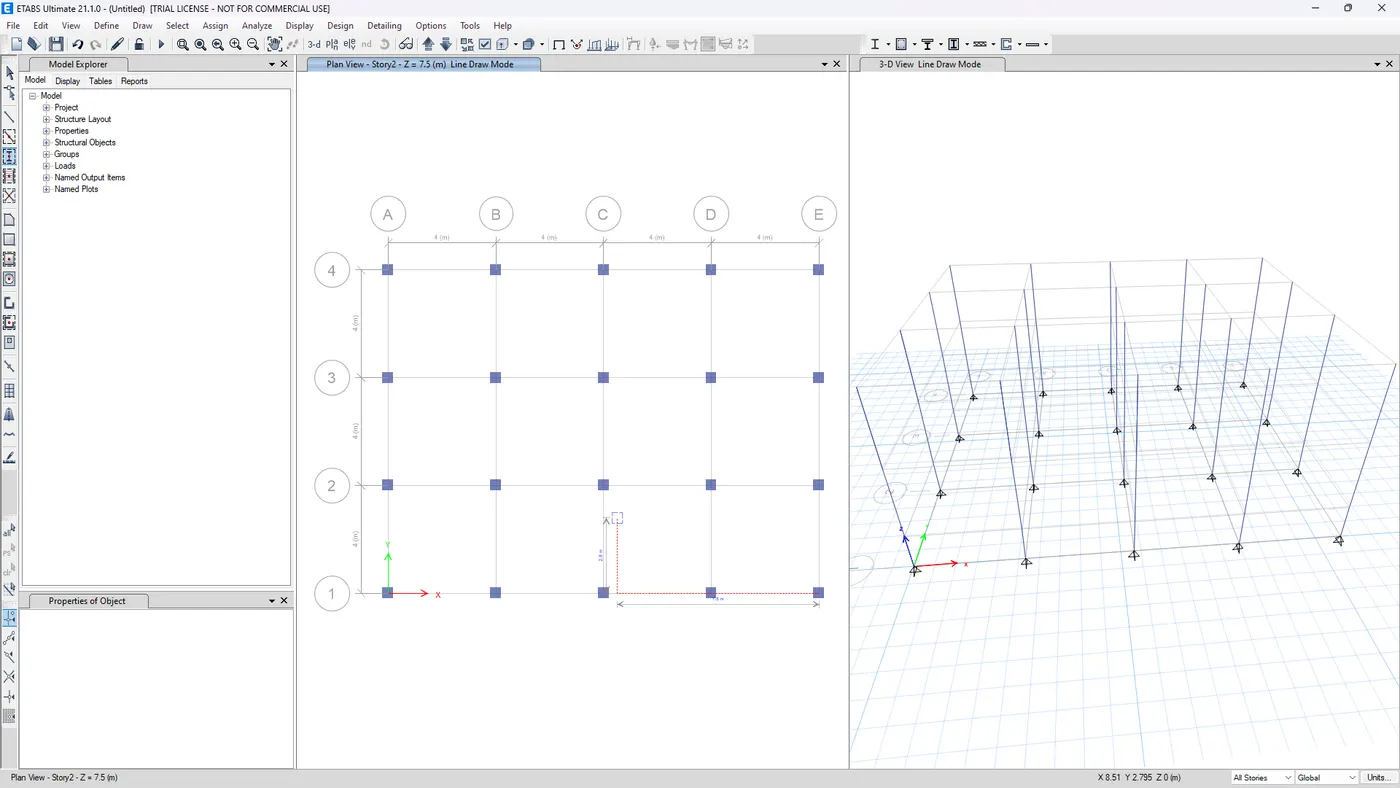
31. To model a column, proceed with the following steps:
ii. Choose the column property type as C400X400.
iii. Select the "All Story" option in the bottom right corner.
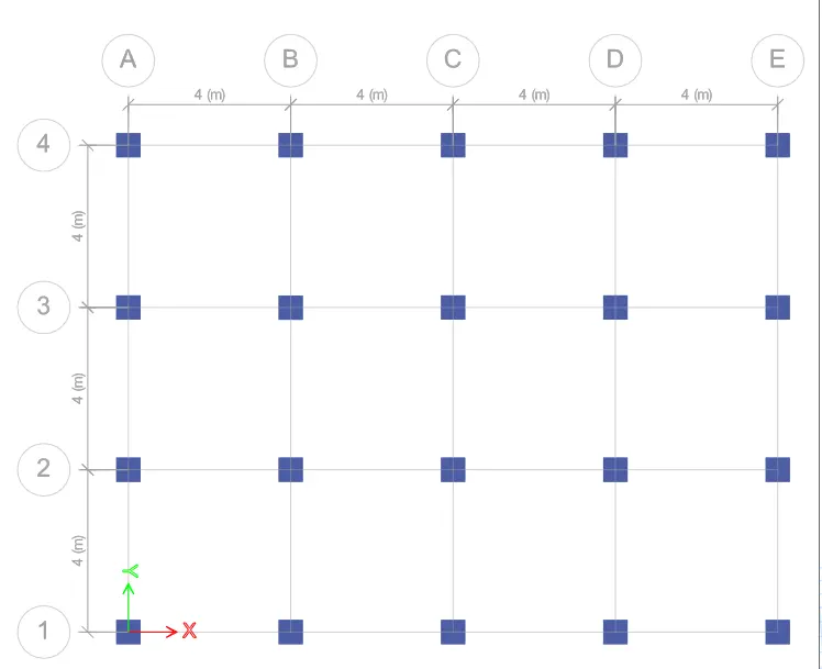
iv. Position the cursor on the grid and click to create the column as demonstrated below.
i. Click on the Quick Draw Beam icon in the panel.
ii. Choose the beam property type as B300X400.
iii. Select the "All Story" option in the bottom right corner.
iv. Position the cursor on the line between the grids and click to create the beam as illustrated below.
ii. Click on the plan icon at the top of the panel.
iii. Select "Storey 1" from the options provided.
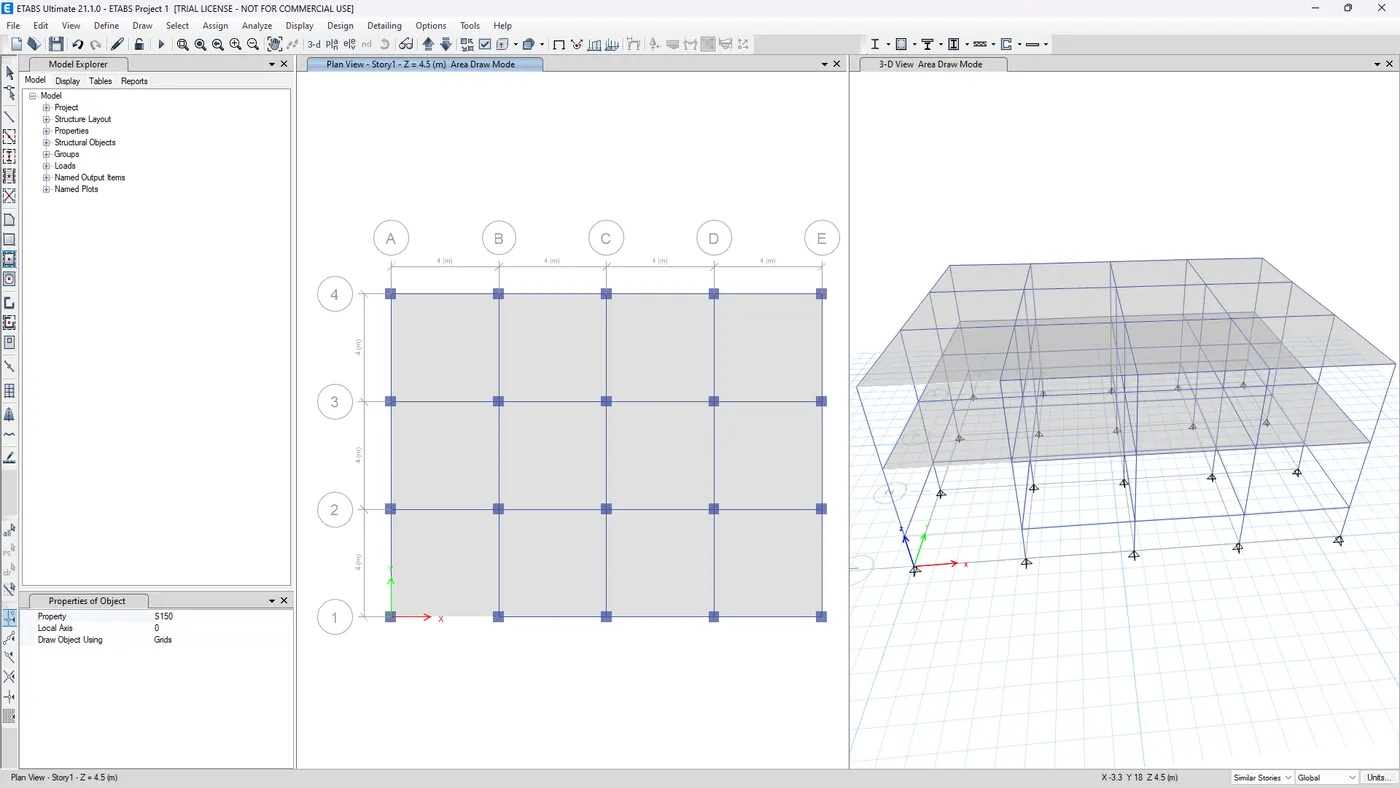
i. Click on the Quick Draw Floor icon.
ii. Choose the slab property type as S150.
iii. Click inside the frame.
iv. The slabs will be generated in the similar stories.
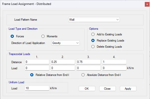
36. For Beams:
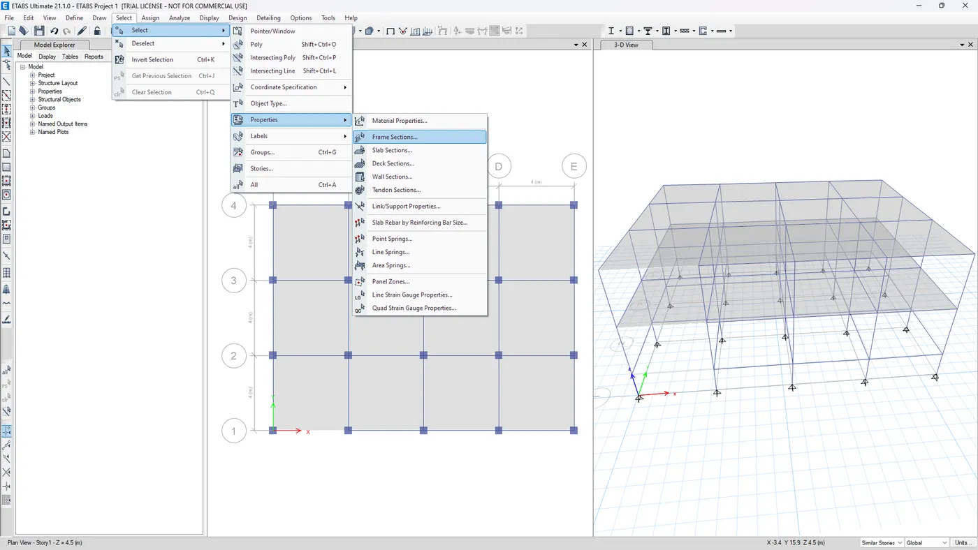
i. Navigate to "Select" -> "Select" -> "Property" -> "Frame Section".
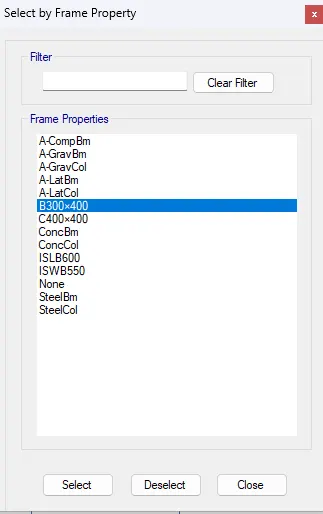
i. Choose the beam type.
ii. Go to "Assign" -> "Frame Loads" -> "Distributed".
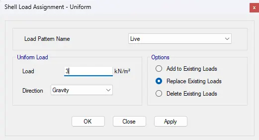
For slabs, select the slab property as S150.
ii. To assign uniform shell loads:
iii. Go to "Assign" -> "Shell Loads" -> "Uniform".
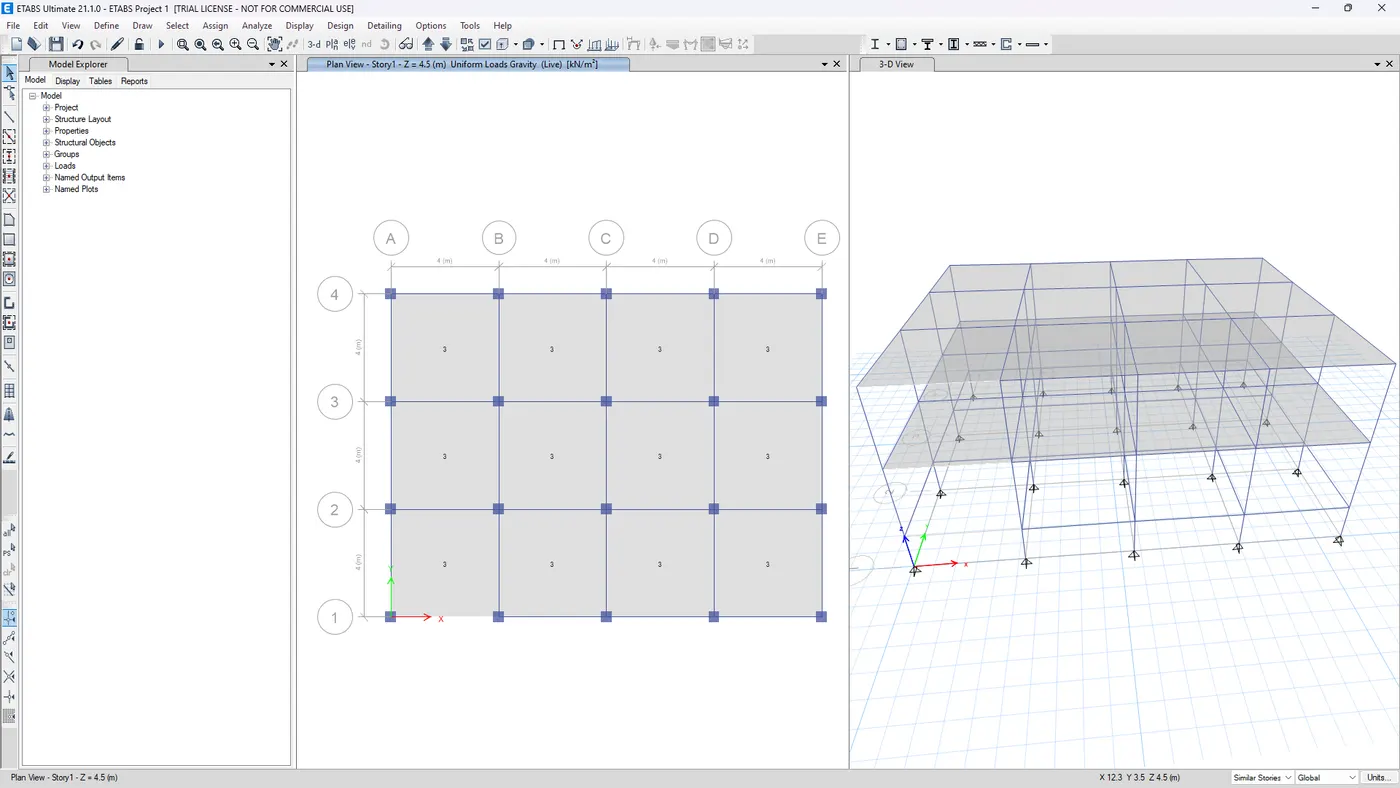
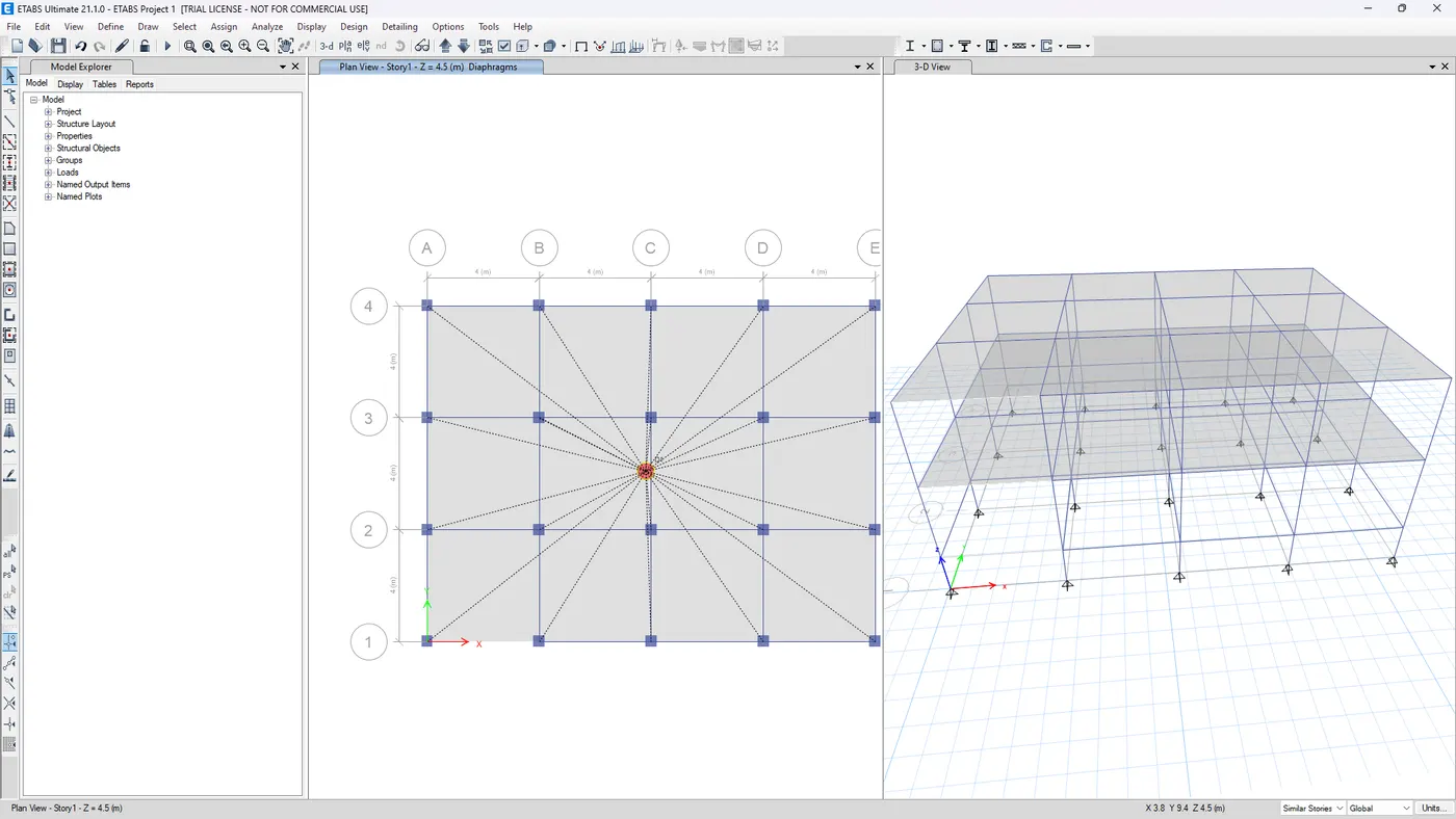
i. Next, go to "Select" -> "Select" -> "Property" -> "Slab Section".
ii. Select "Assign" -> "Shell" -> "Diaphragms" -> "D1".
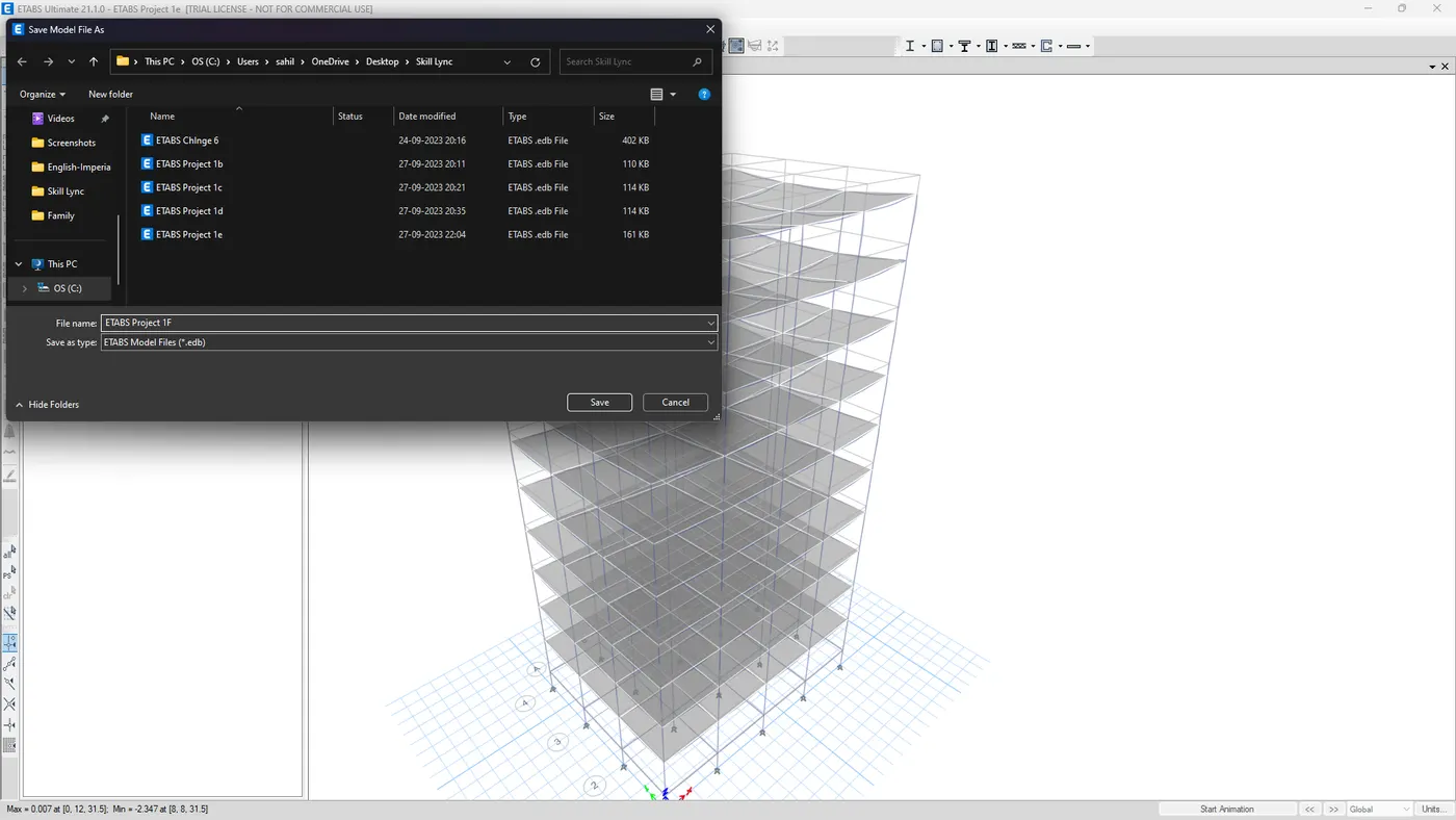
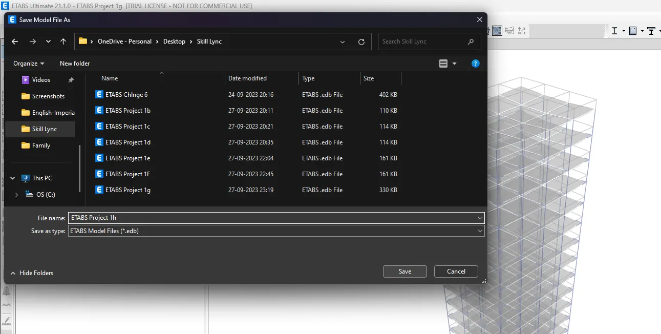
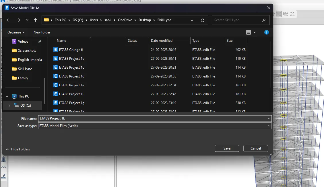
42. Save the model by following these steps:
i. Go to "File" in the menu bar.
ii. Select "Save As" to save the model with a chosen file name and location.
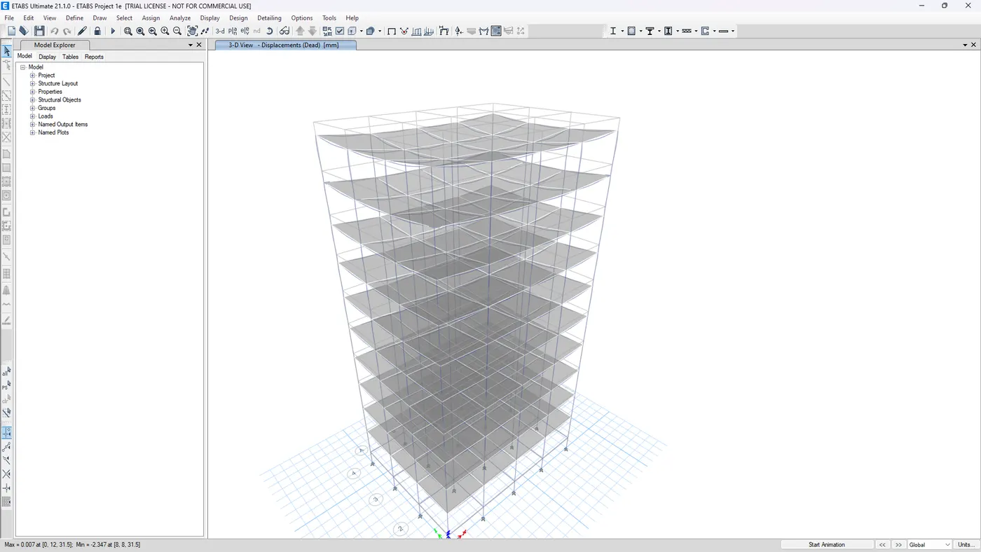
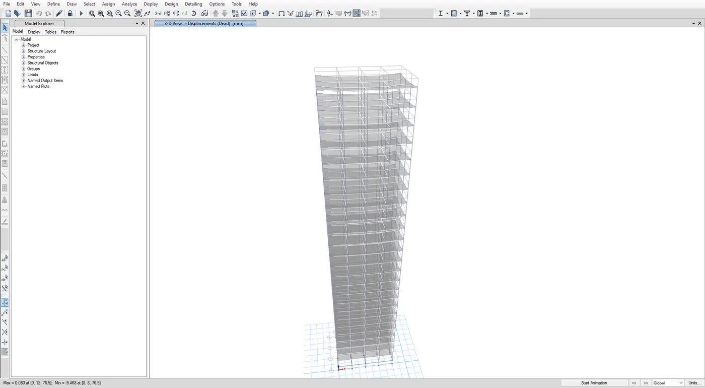
ii. After the analysis is complete, the deformed shape of the building will be displayed.
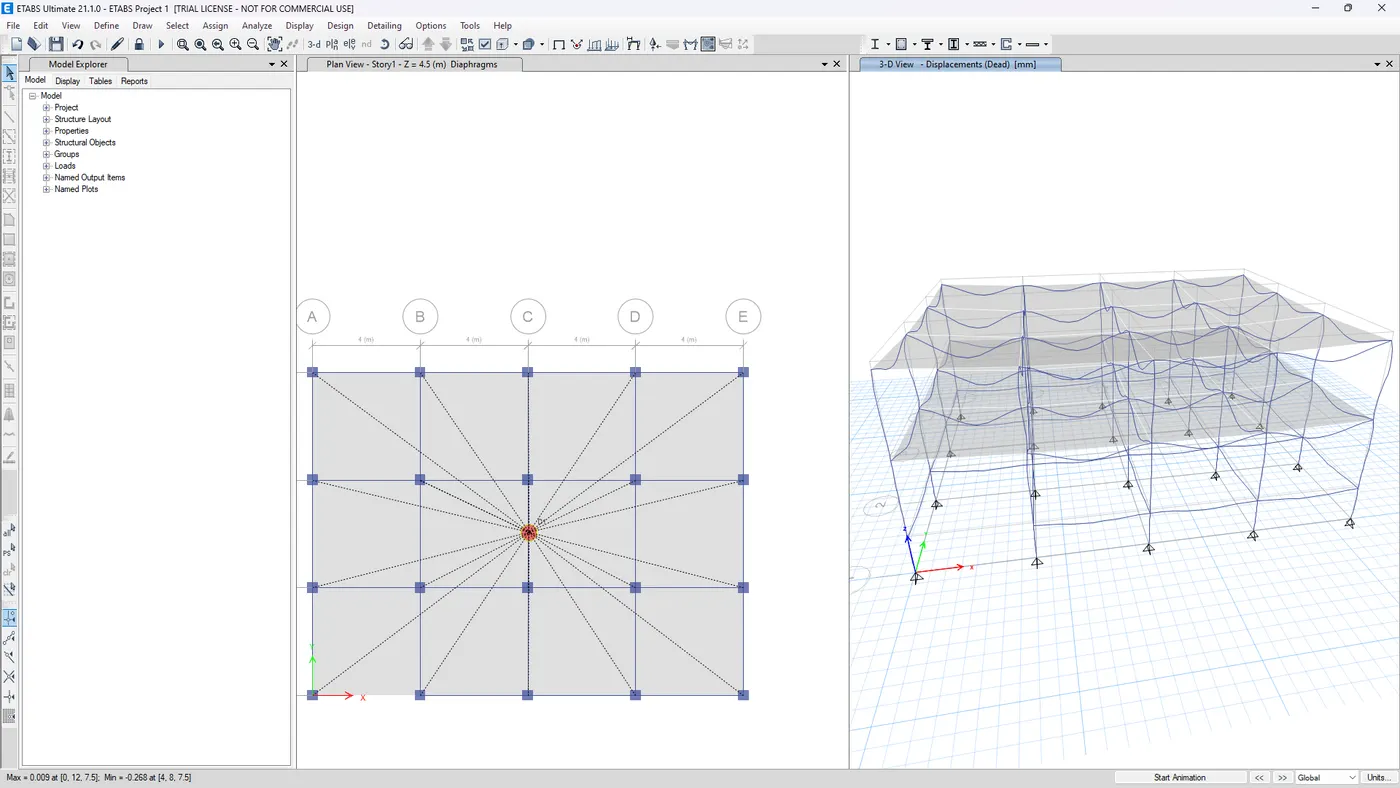
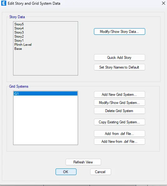
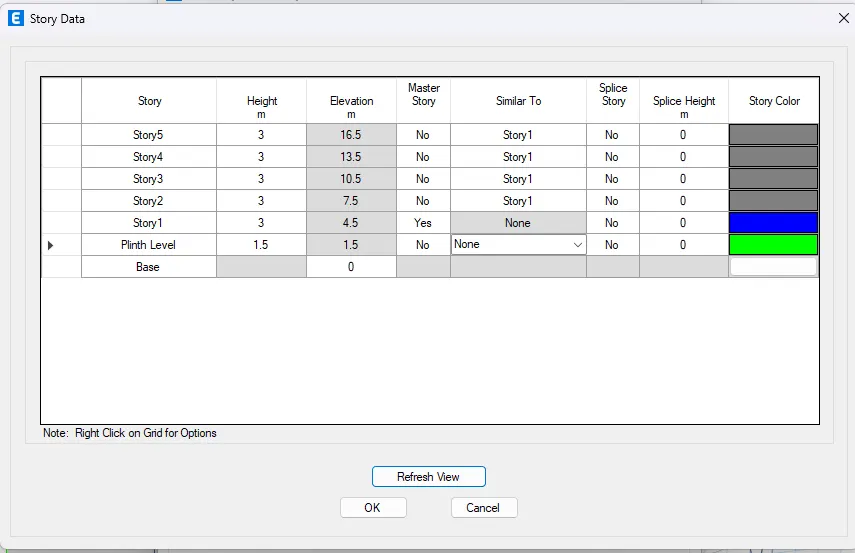
48. Click refresh view.
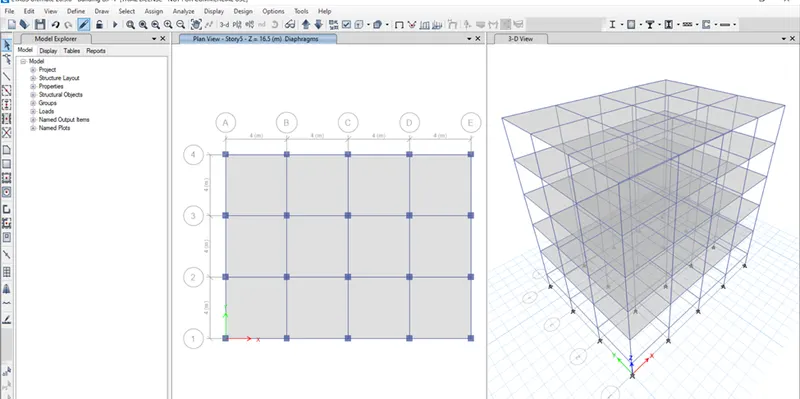
49. Click Display shell load assign icon in the panel, Change the load pattern to live and click apply and ok.
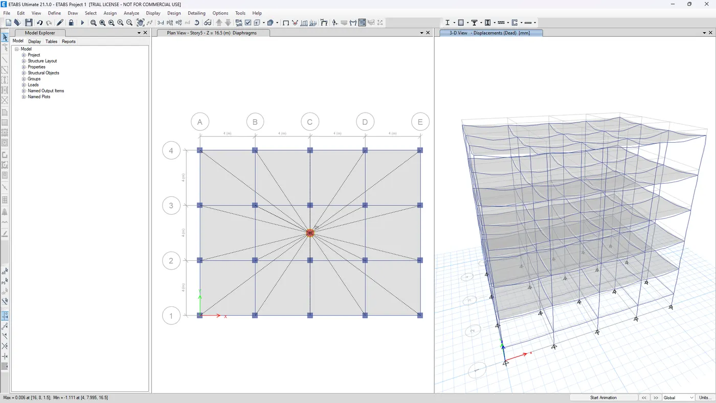
53. Click File -> Save as -> ETABS Project 1c
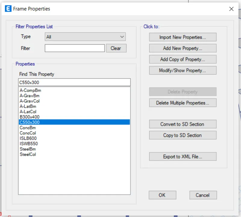
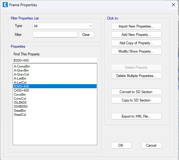
55. Go to Define -> Section property -> Frame section
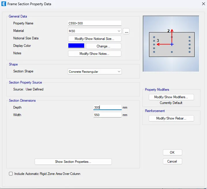
58. Click ok
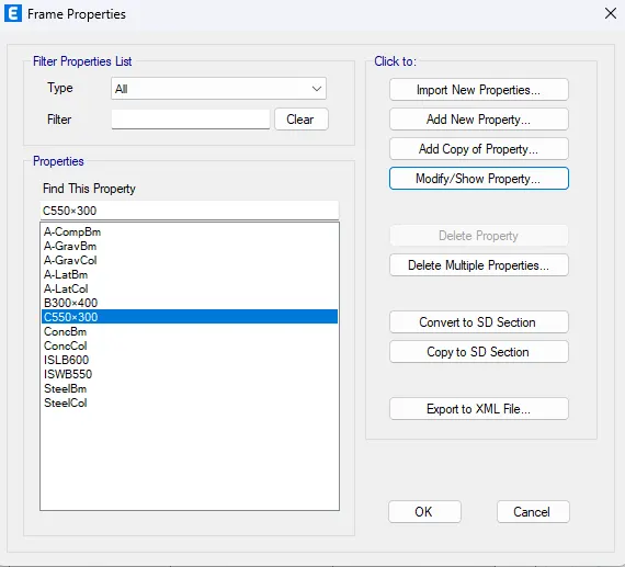
60. Click Select -> Properties -> Frame section
61. And select the column which created now and click Select.
62. Click Assign -> Frame -> Local axes.
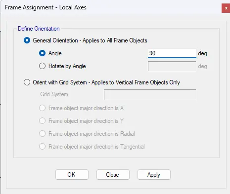
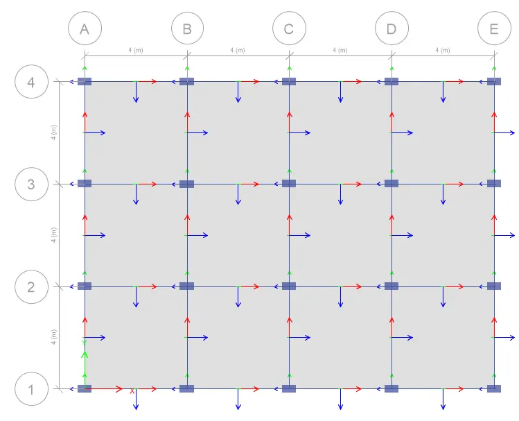
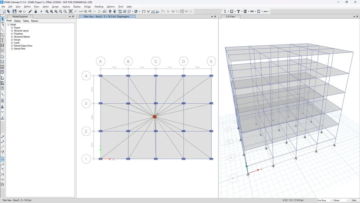
64. Click run analysis icon.
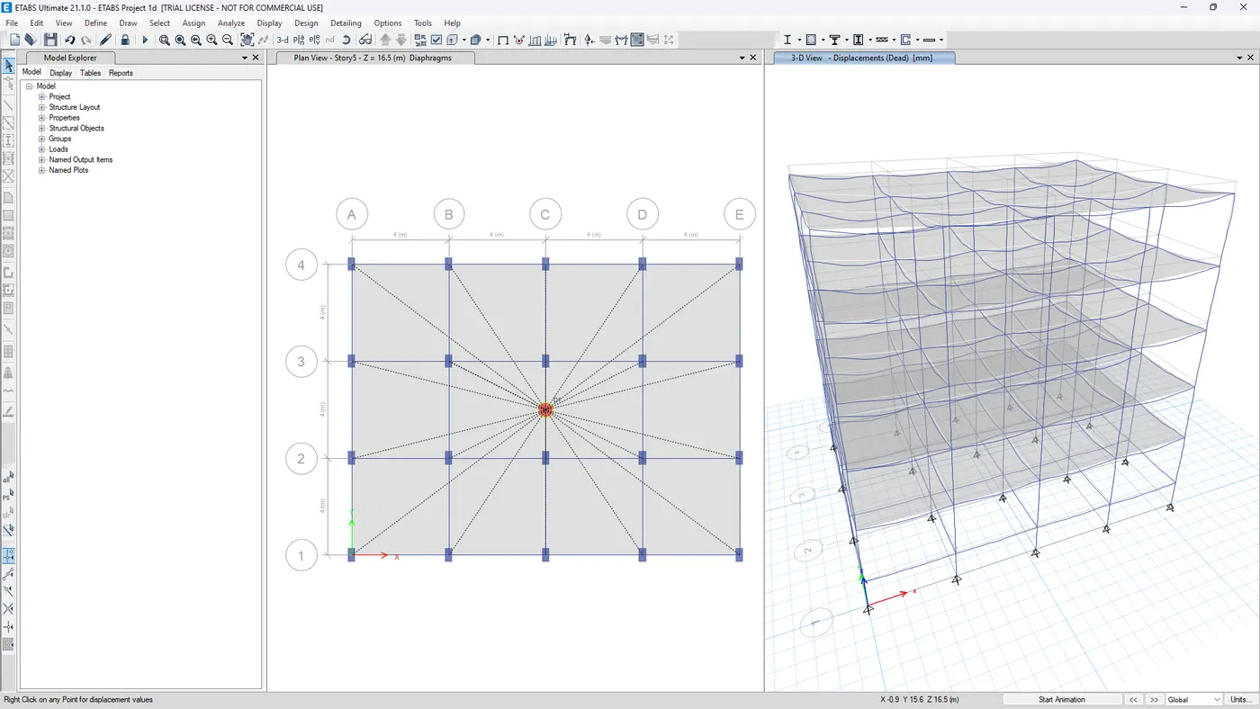
70. Change angle to 0.
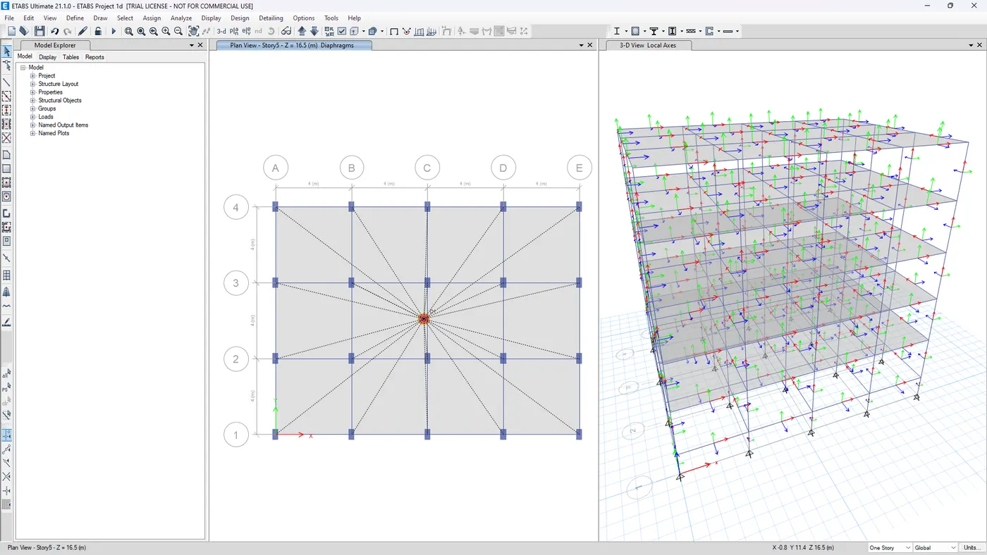
71. Select the slab and assign it as diaphragm.
Analysis:
72. Click run analysis icon.
Save as:
73. Click File -> Save as -> ETABS Project 1e
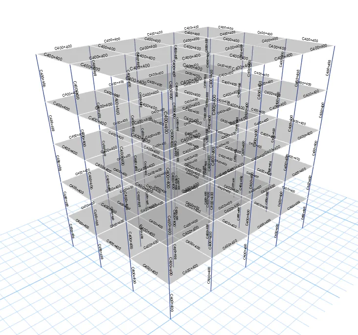
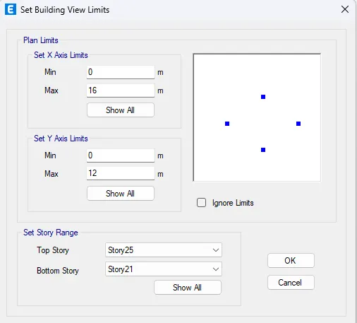
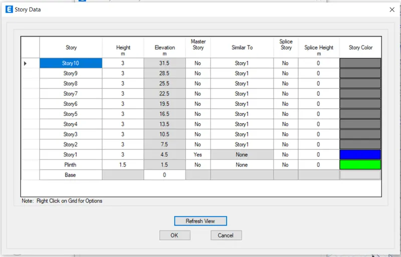
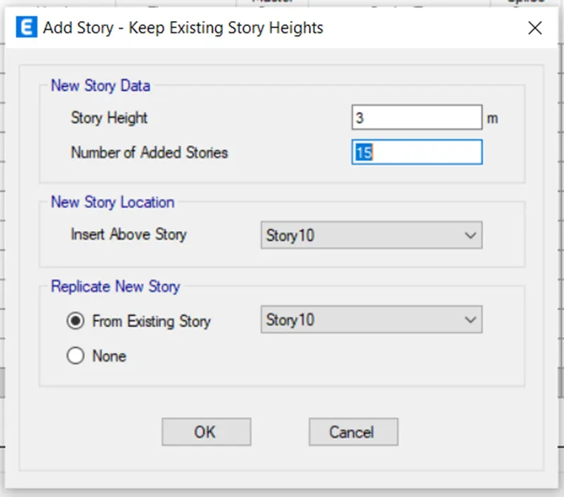
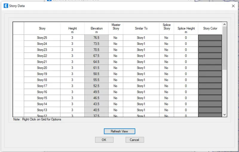
74. To add extra stories, go to Edit -> Edit story and grid system -> Modify/ Show story data.
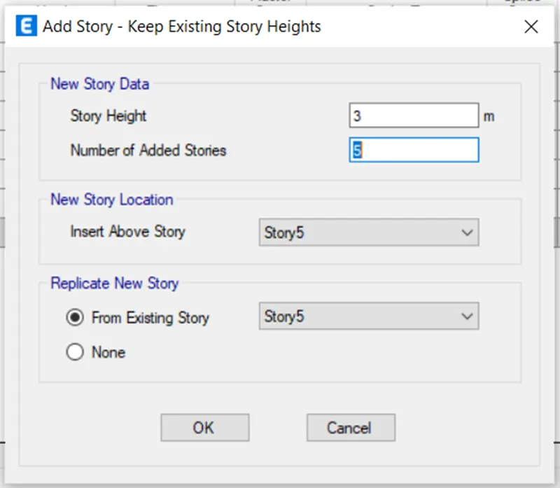
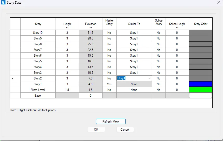
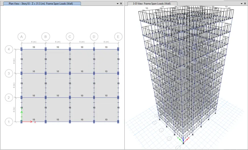
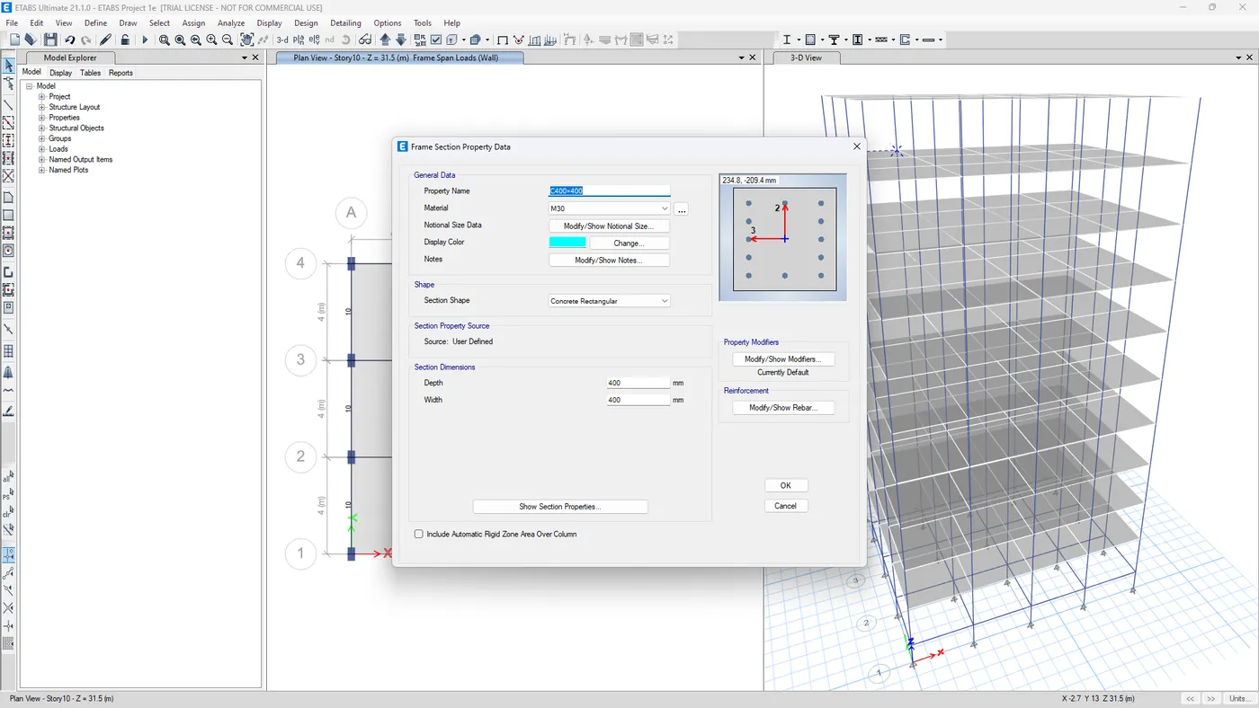
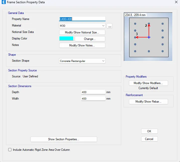
80. Click Define -> Section property -> Frame section
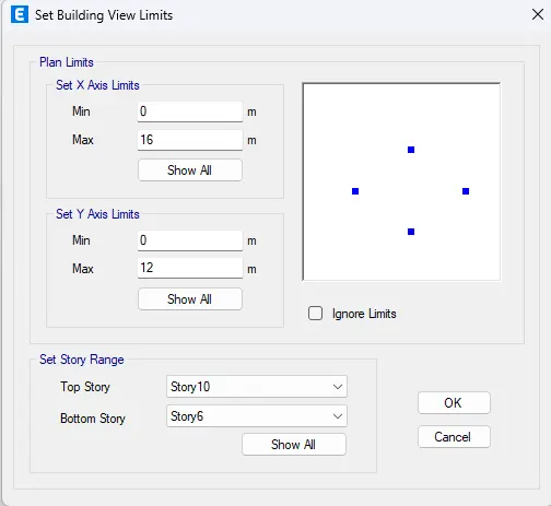
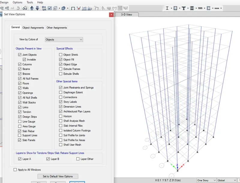
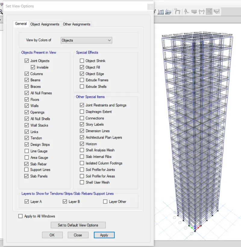
84. Click Set display option, uncheck Beams and Floors option.
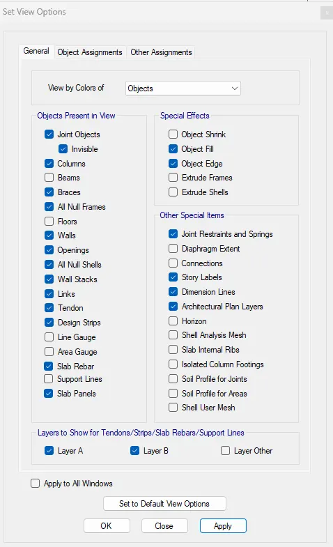
86. Only column is visible.
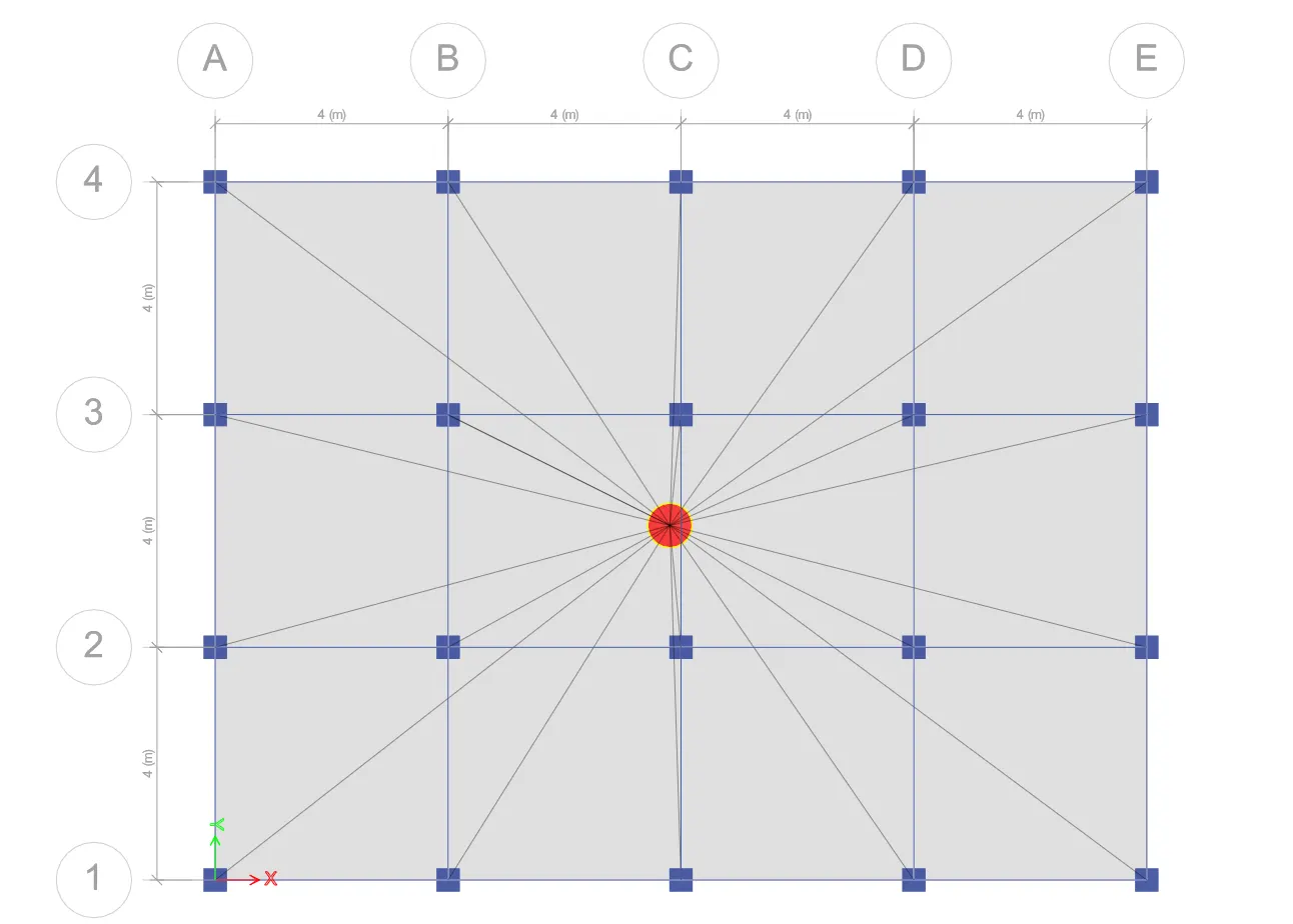
92. Select the slab and assign it to diaphragm.
Analysis:
93. Click run analysis icon.
Save as:
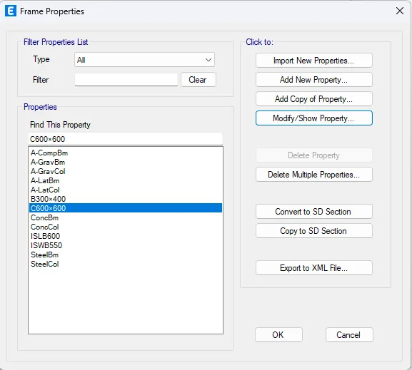
96. Changing all column size to C600X600.
97. Click set display option and uncheck beams and floors
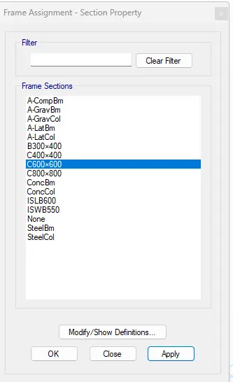
100. Go to Assign -> Frame -> Section property and select C600X600.
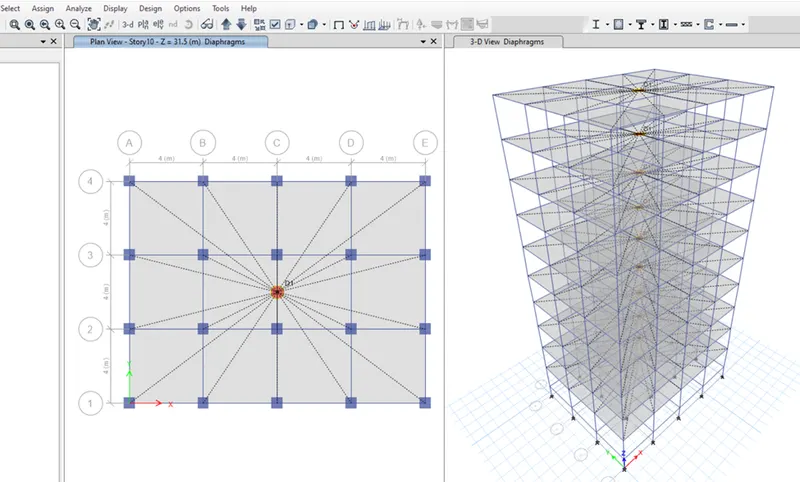
102. Select the slab and assign it to diaphragms.
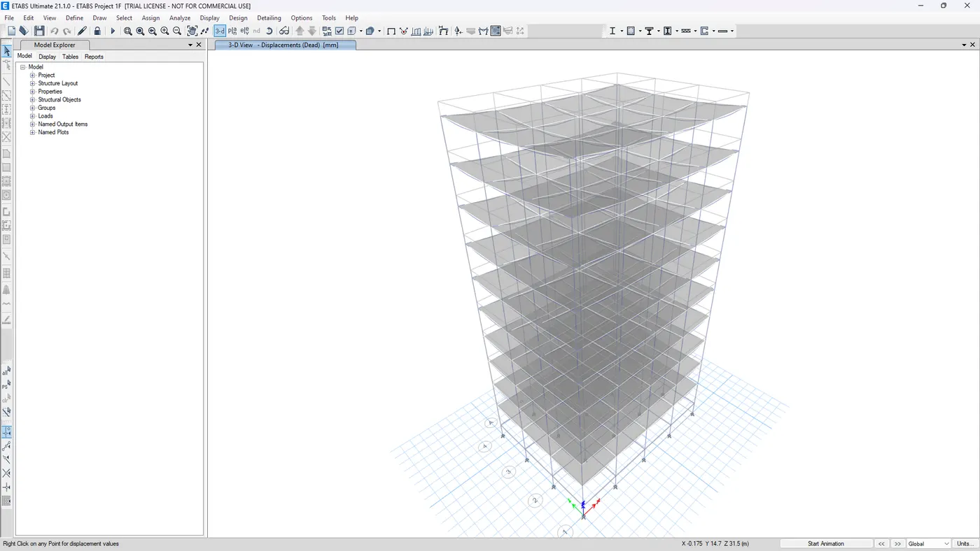
103. Click run analysis icon.
Save as:
104. Click File -> Save as -> ETABS Project 1g
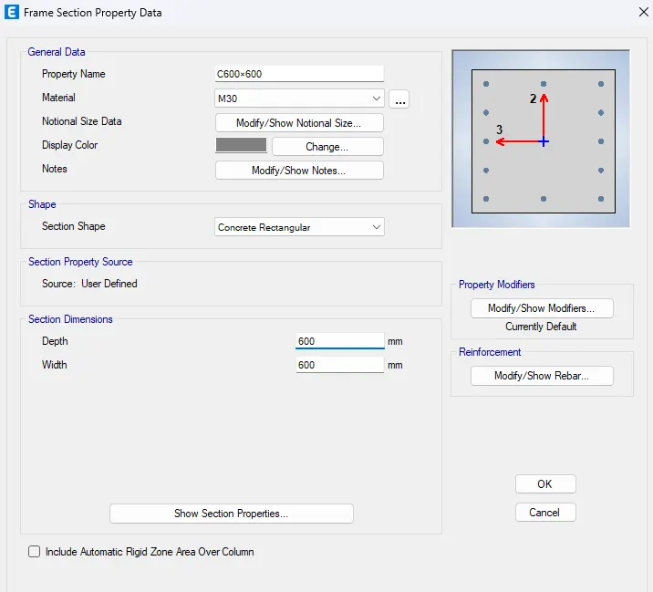
109. Creating new column size:
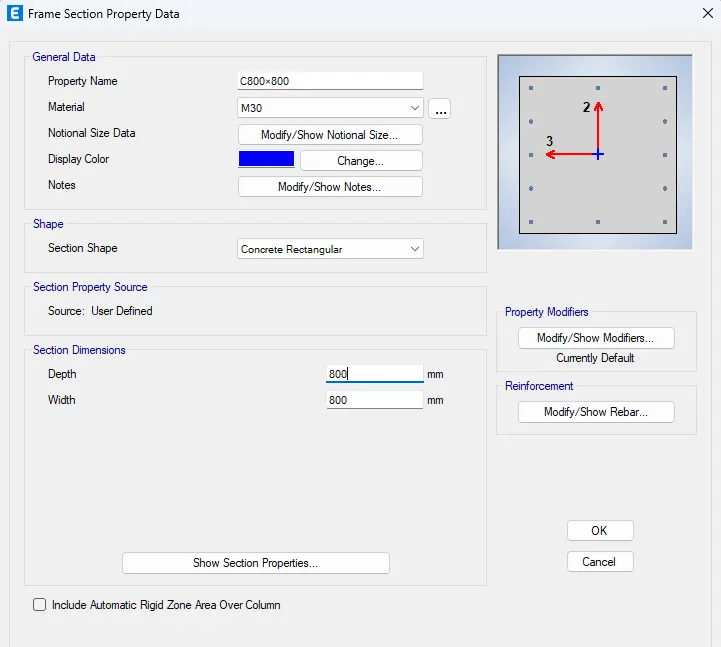
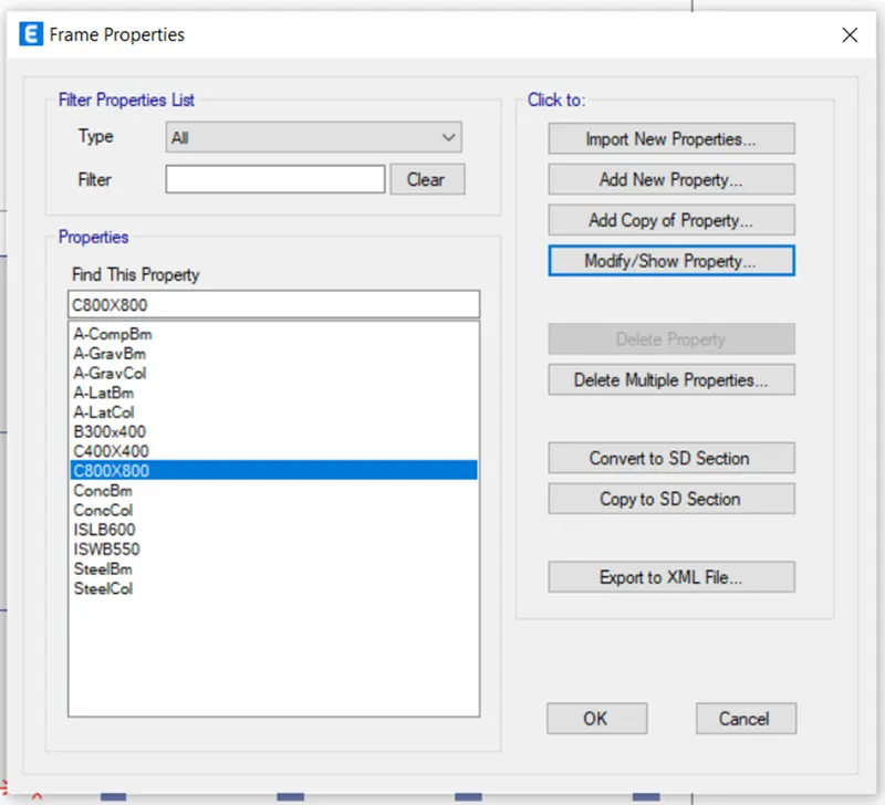
110. Go to Define -> Section properties -> Frame section.
115. Go to set display option and uncheck beams and floors.
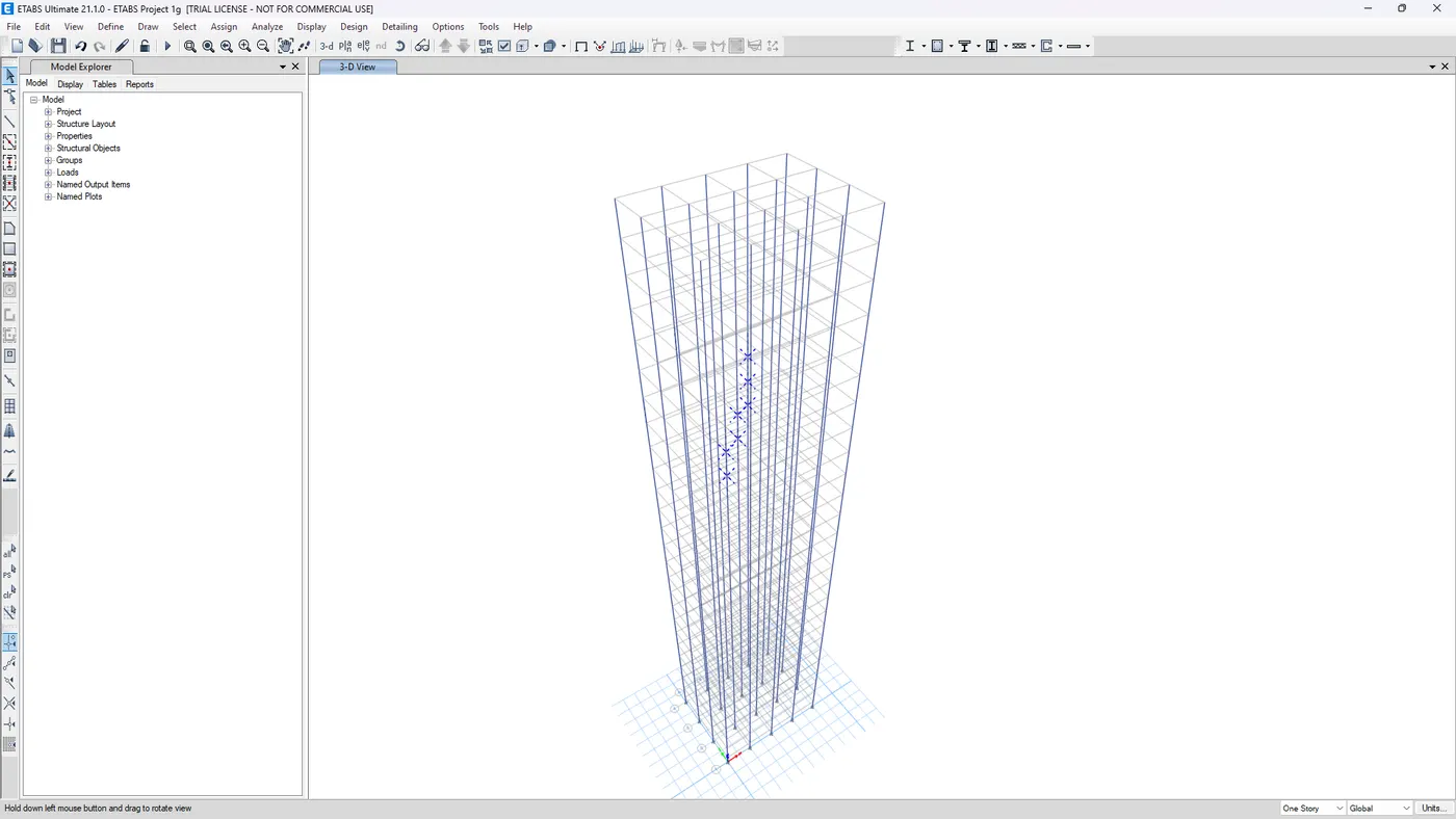
117. For top 5 Stories :.
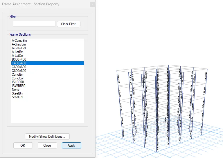
120. Follow the above procedure.
123. It is already assigned as C800X800 in the beginning.
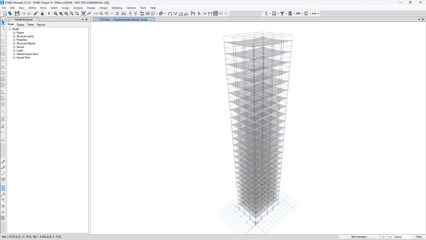
124. Check the loads in all the stories and also ensuring the diaphragms properties.
125. Click run analysis icon.
Save as:
126. Click File -> Save as -> ETABS Project 1h
128. Click Set display option icon and uncheck beams and slabs.
130. Click Assign -> Frame -> Section property
131. Click run analysis icon.
Save as:
132. Click File -> Save as -> ETABS Project 1j
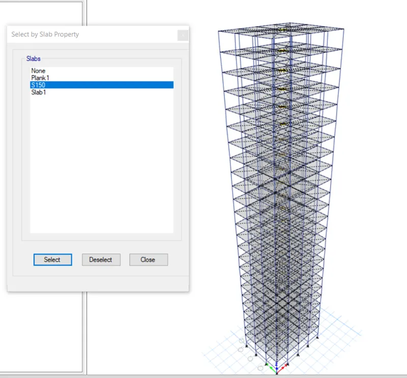
134. Click Select -> Select -> Properties -> Slab section.
135. Select S150 and click select.
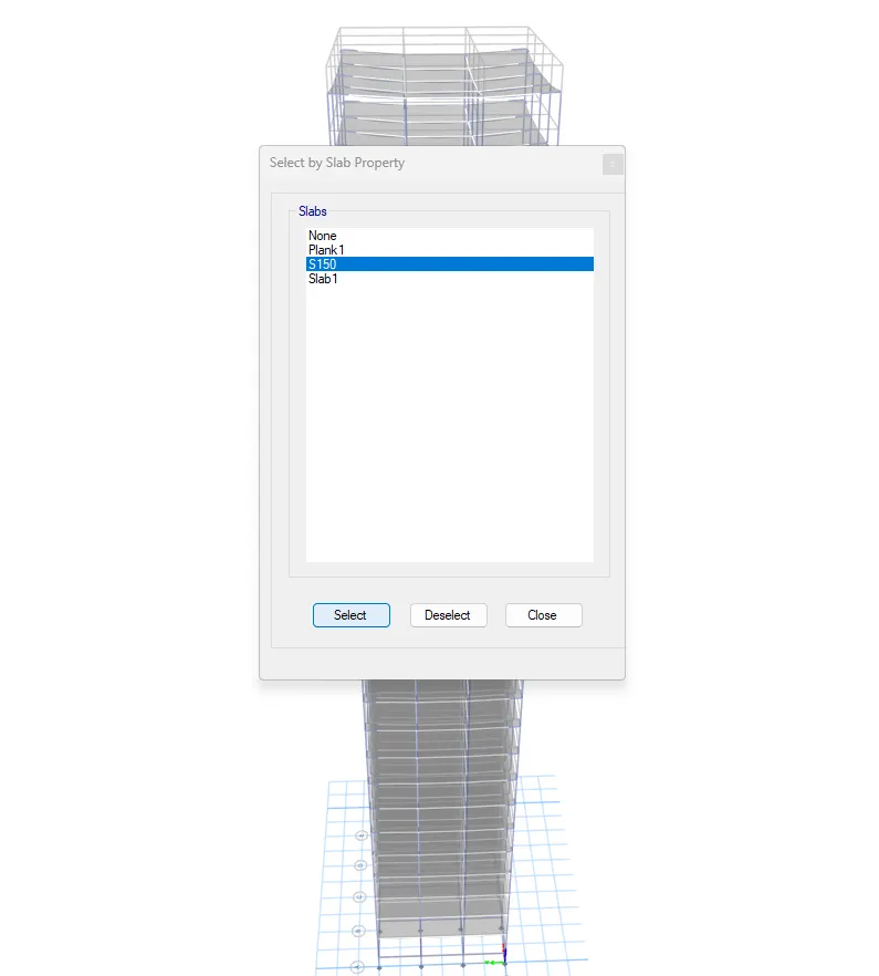
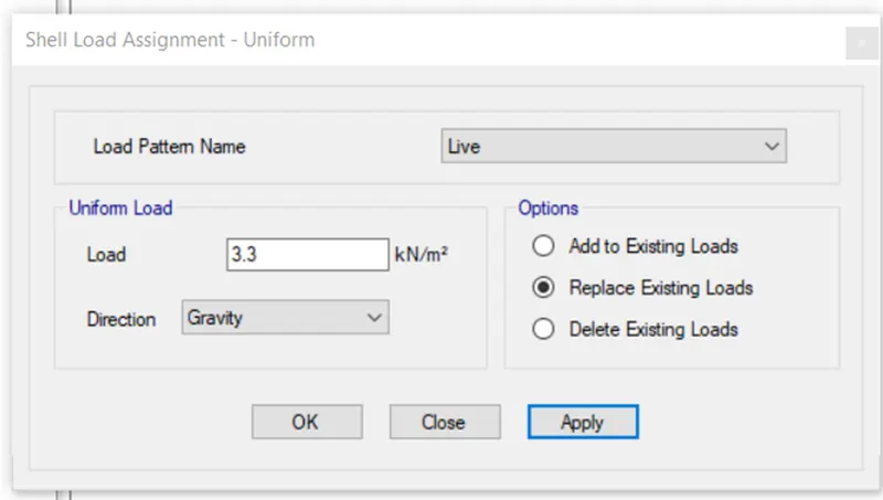
137. Give load as 3.3 and select replace existing loads.
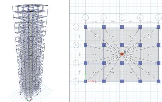
140. Click run analysis icon.
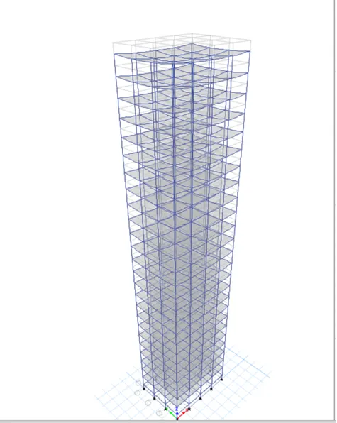
141. Click File -> Save as -> ETABS Project 1k
142. To increase 20% mass:
143. Click Select -> Select -> Properties -> Slab section.
144. Select S150 and click select.
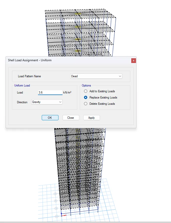
146. Give load as 3.6 and select replace existing loads.
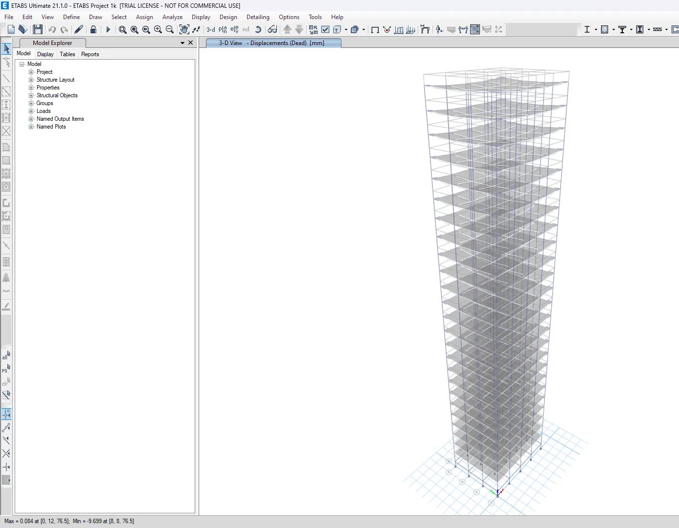
148. Click run analysis icon.
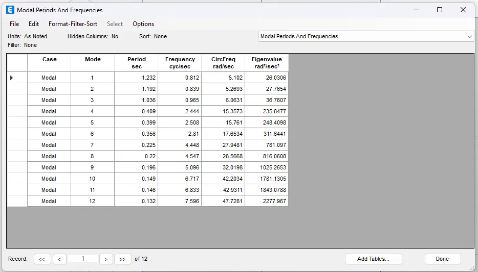
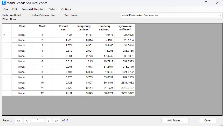
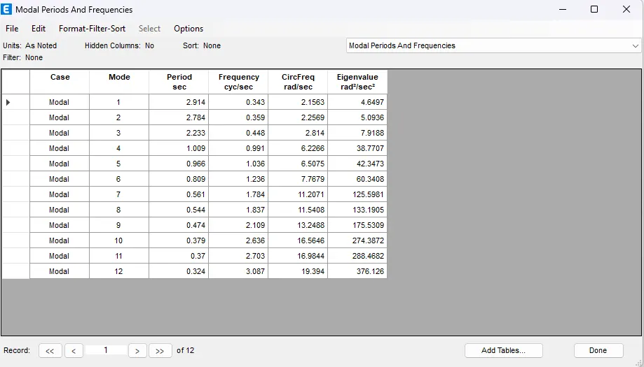
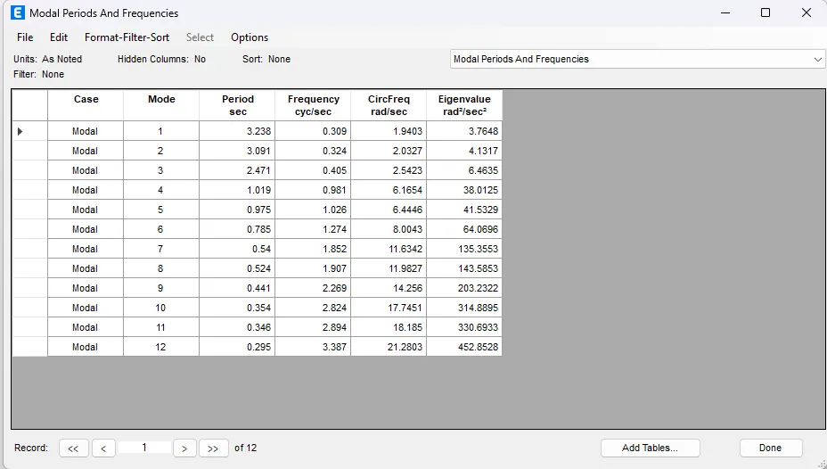
RESULTS:
* The results have been taken from the Tables from respective building models.
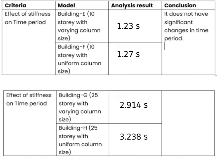
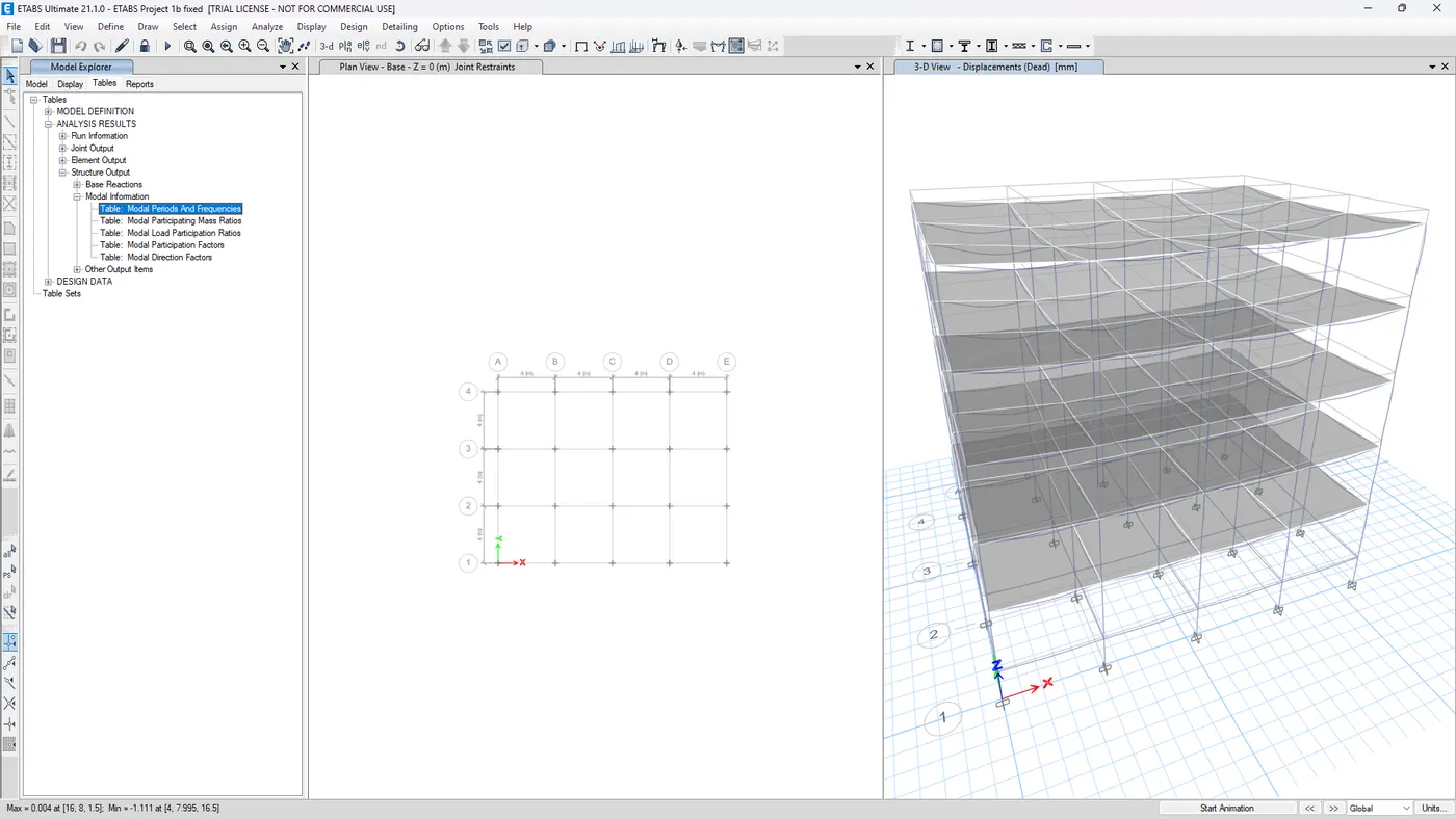
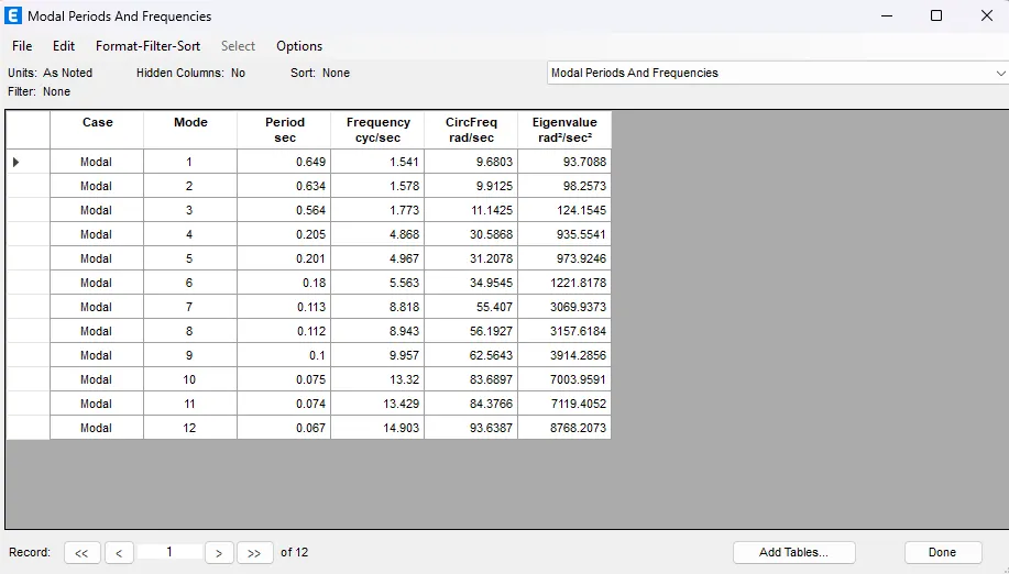
149. Click Tables -> Analysis Results -> Structural output -> Model Information -> Model periods and Frequencies-> Show table
150. Click File -> Open, for respective building model.
BUILDING E:
BUILDING F:
BUILDING G:
BUILDING H:
* The results have been taken from the Tables from respective building models.
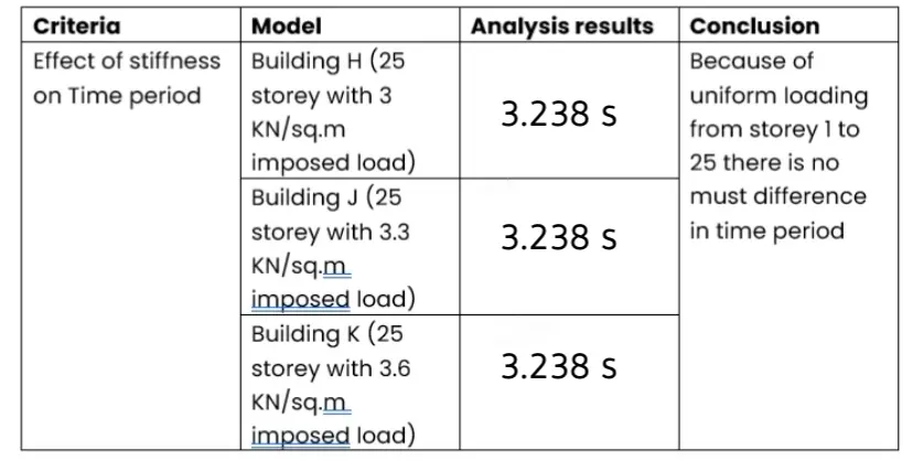
BUILDING H:
BUILDING J:
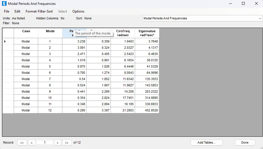
BUILDING K:
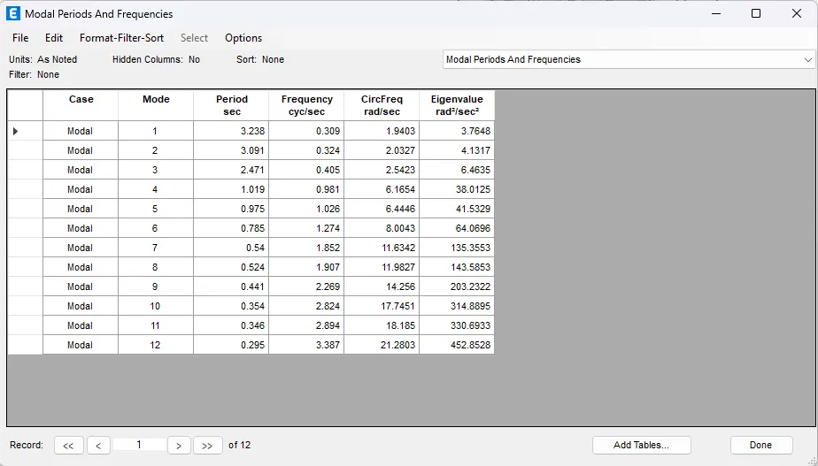
* The results have been taken from the Tables from respective building models.
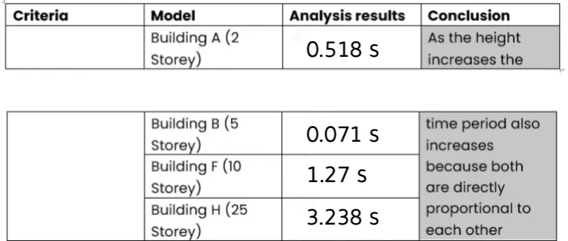
BUILDING A:
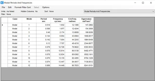
BUILDING B:
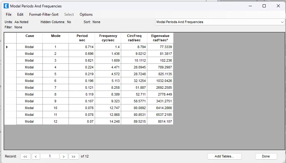
BUILDING F:
BUILDING H:
* The results have been taken from the Tables from respective building models.
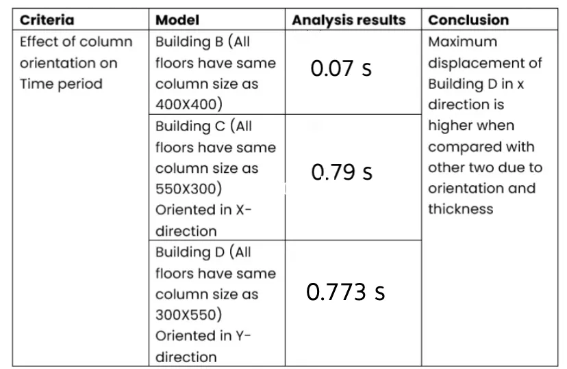
BUILDING B:
BUILDING C:
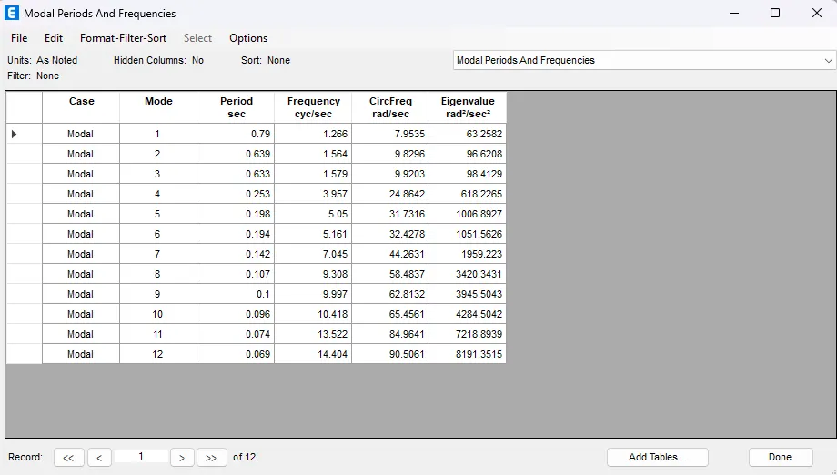
BUILDING D:
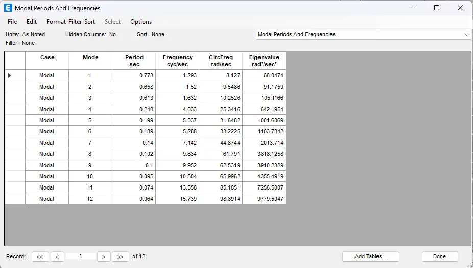
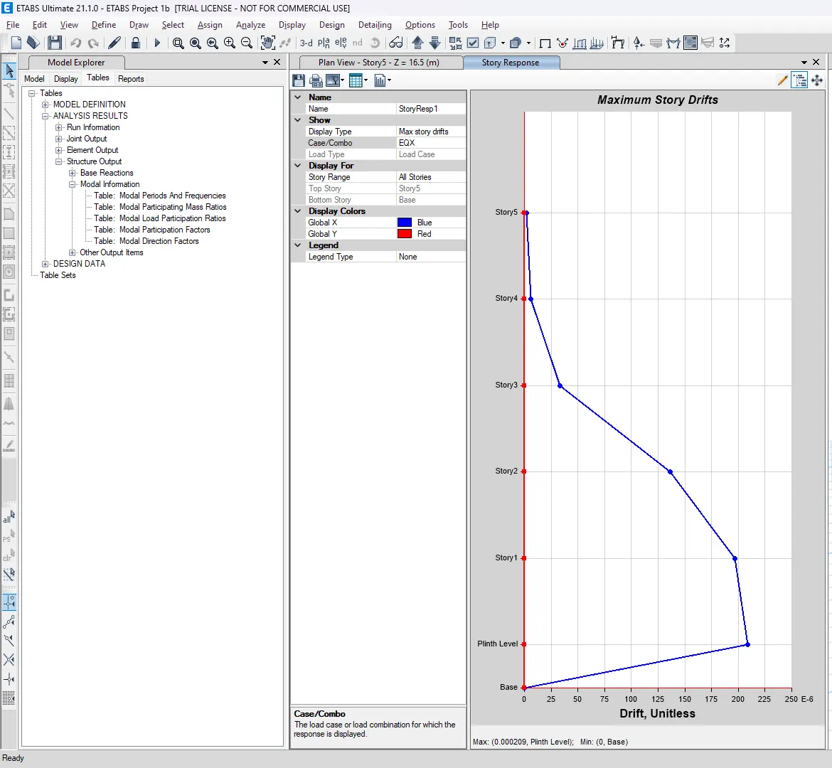
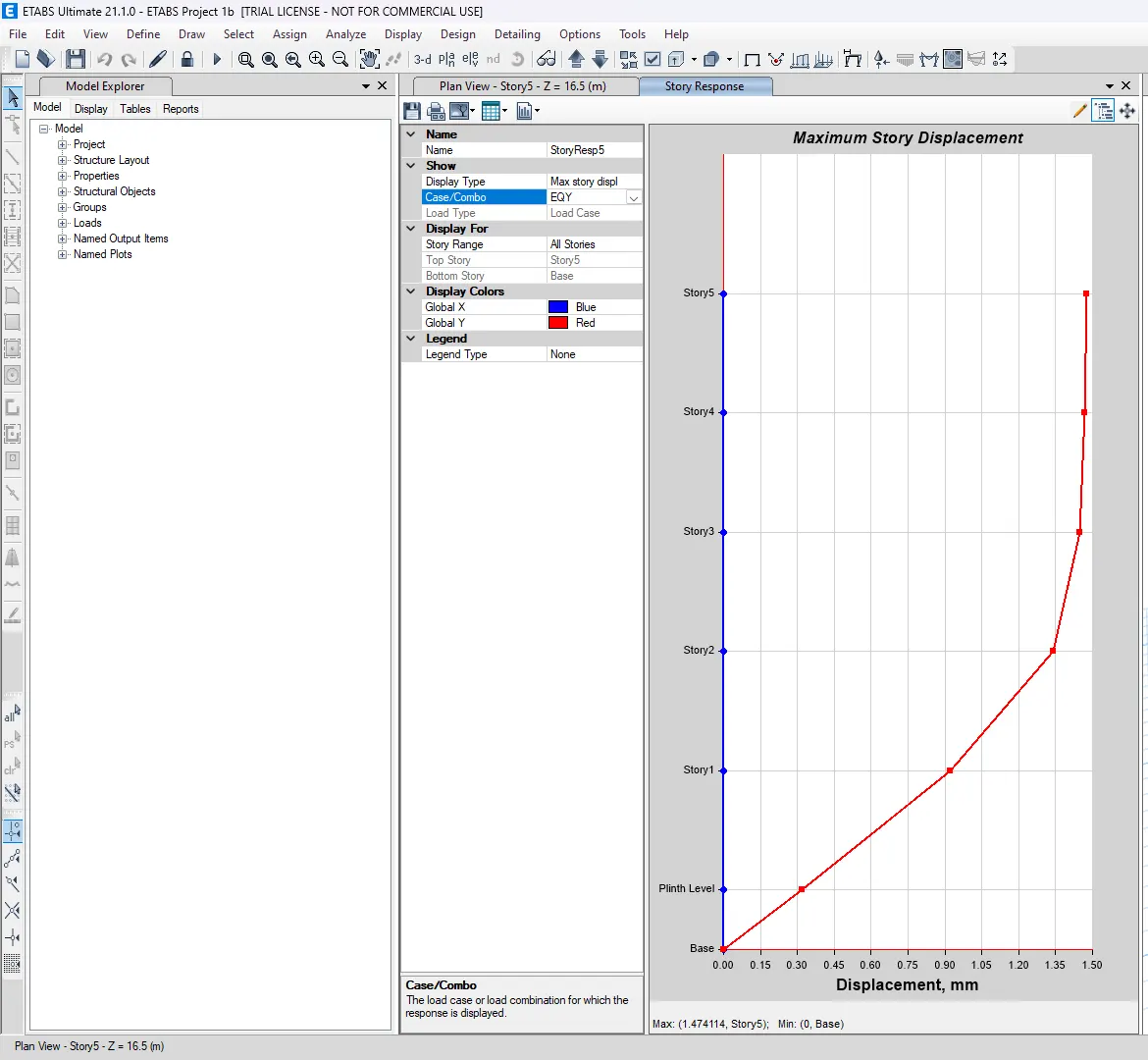
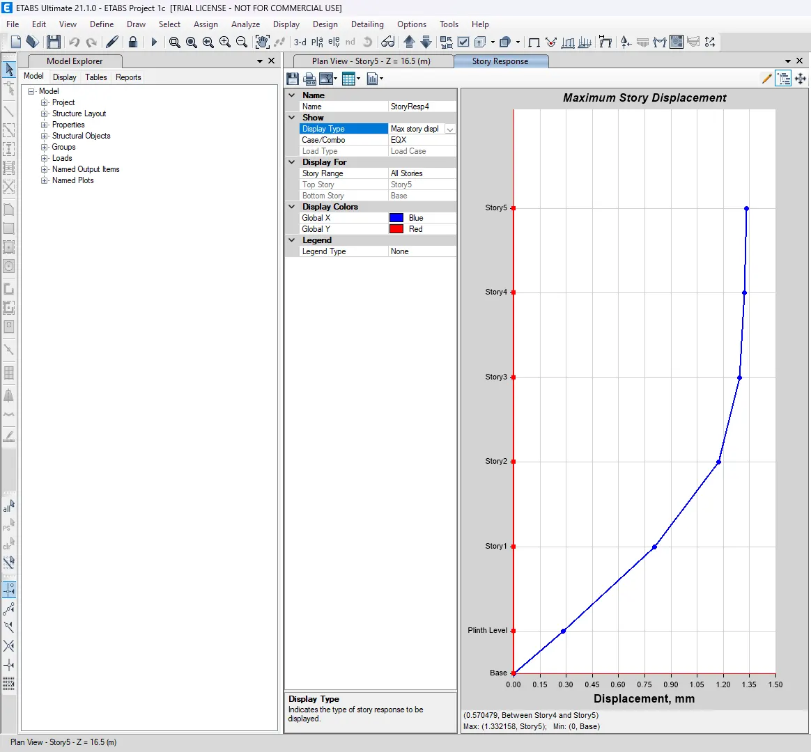
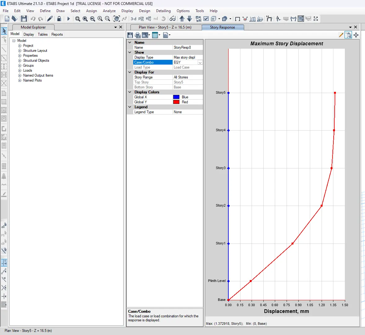
* Maximum storey displacement in X and Y direction:
BUILDING B (EQX):
B (EQY):
BUILDING C (EQX):
C (EQY):
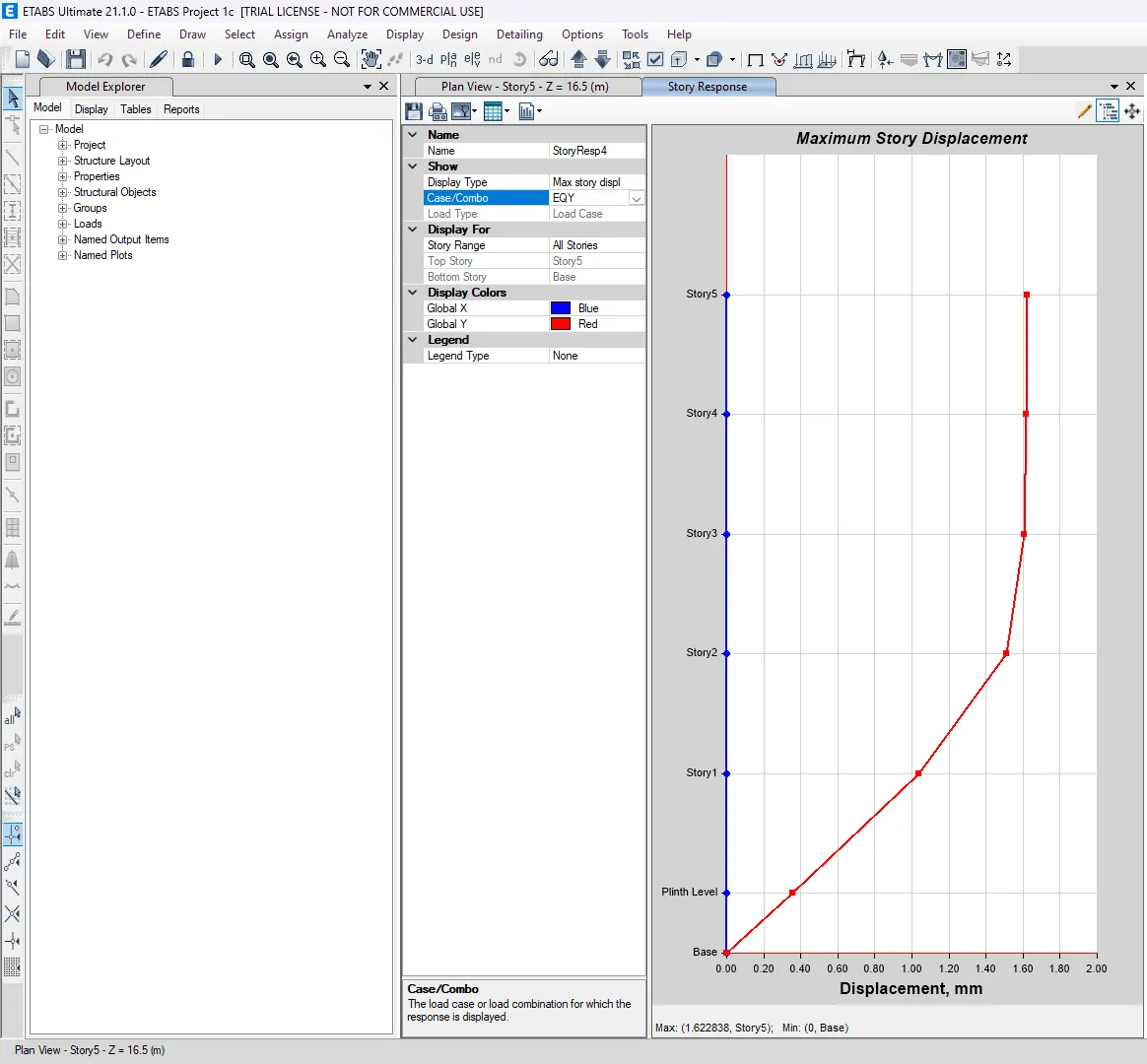
BUILDING D (EQX):
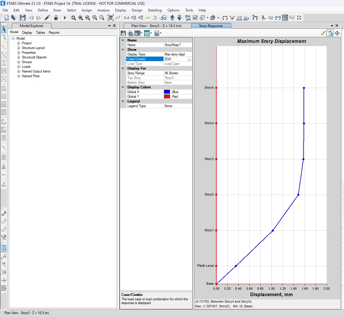
D (EQY):
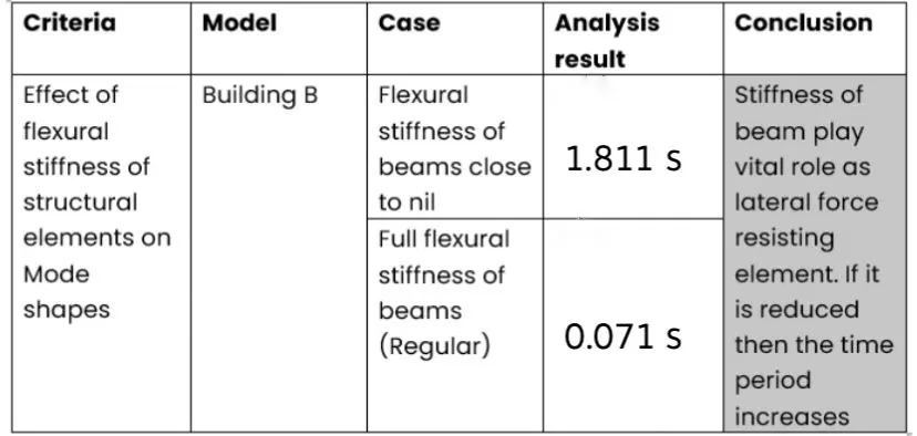
* The results have been taken from the Tables from respective building models.
153. Click Define -> Section properties -> Frame section.
154. Select the existing beam and click modify.
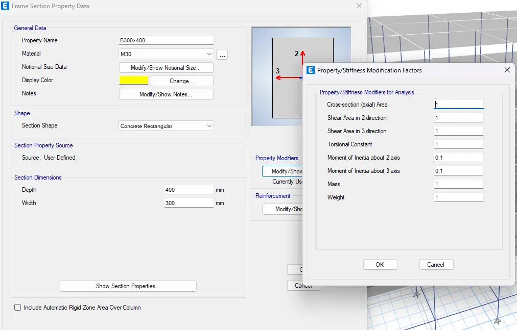
Analysis:
157. Click Run analysis
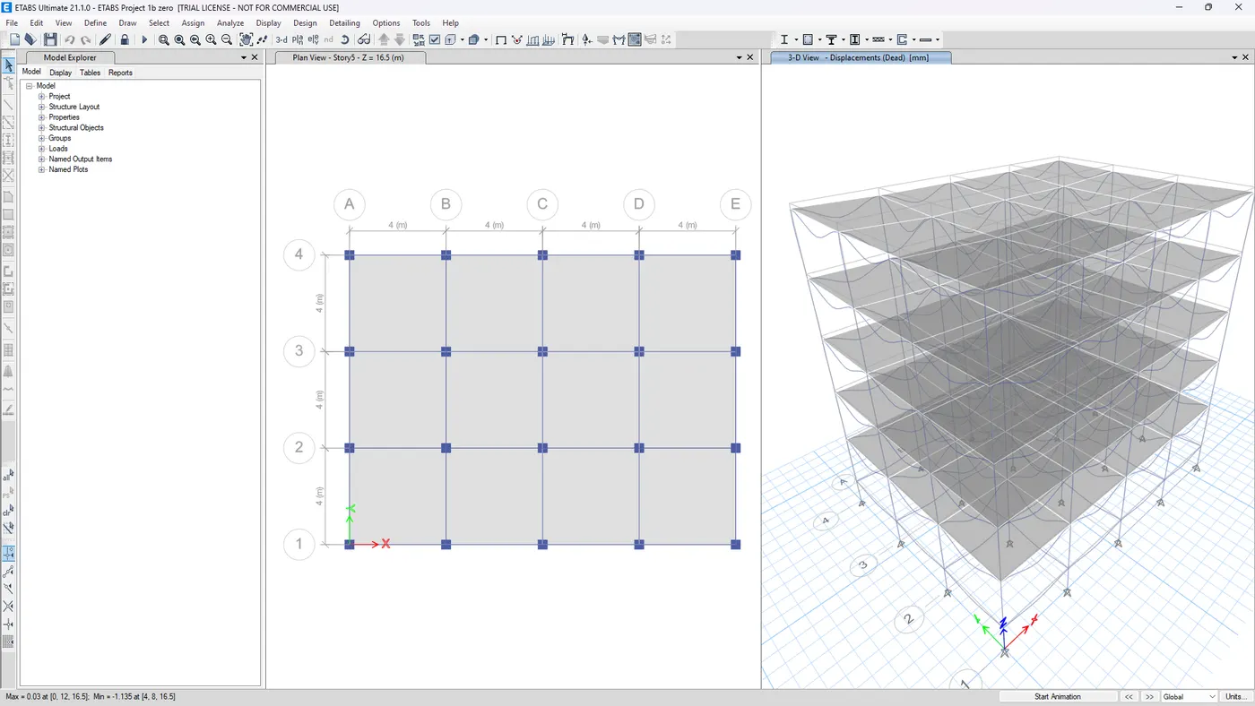
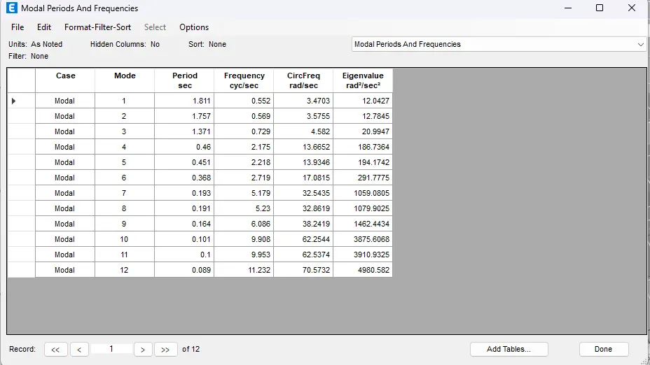
* The results have been taken from the Tables from respective building models.
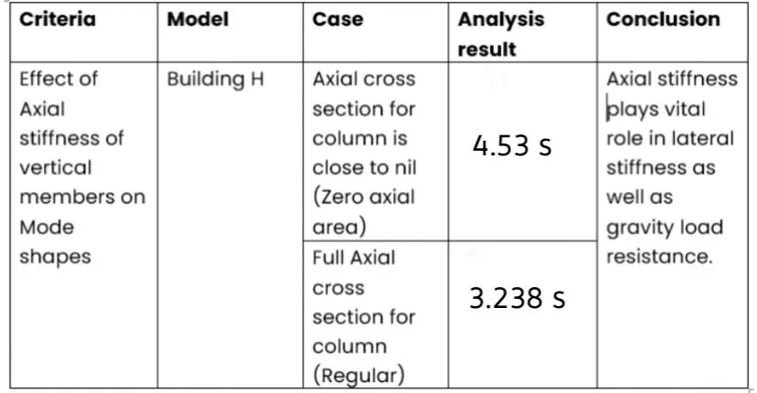
159. Click File -> Save as -> ETABS Project 1h zero
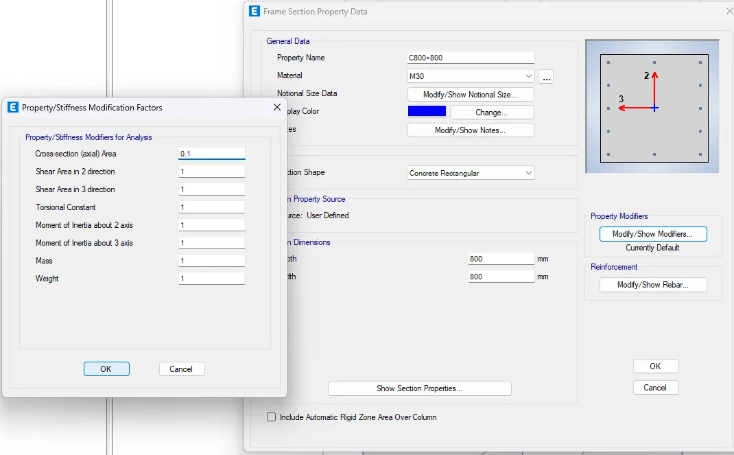
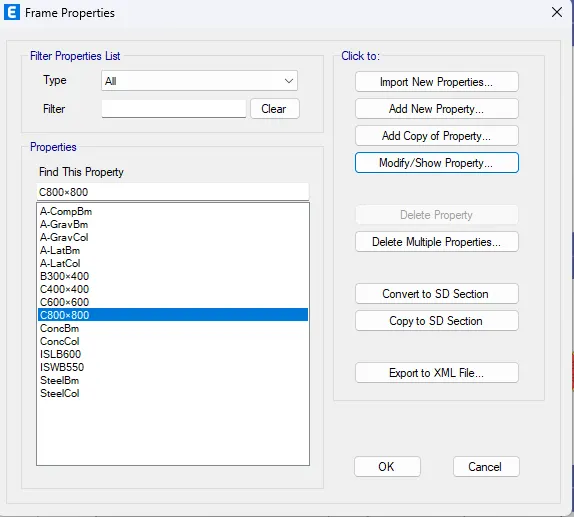
163. Click Run analysis icon
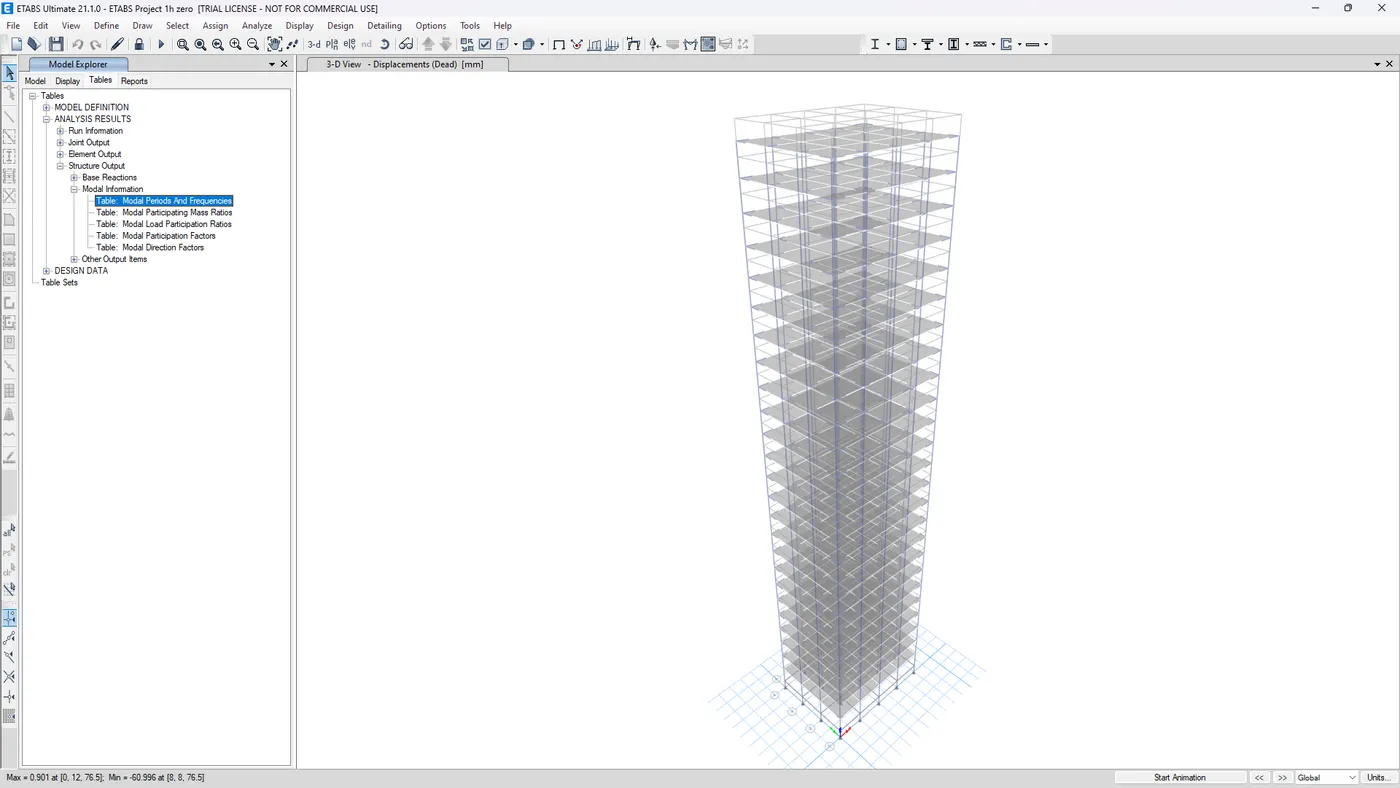
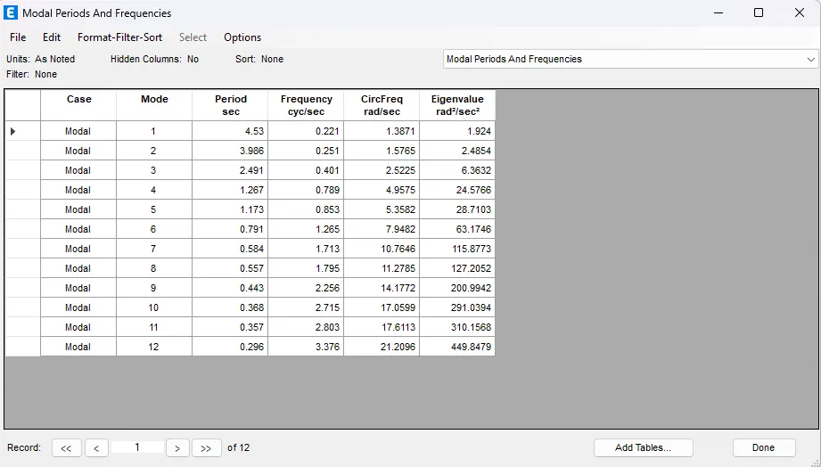
* The results have been taken from the Tables from respective building models.
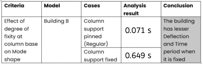
165. open file -> Save as -> ETABS Project 1b fixed
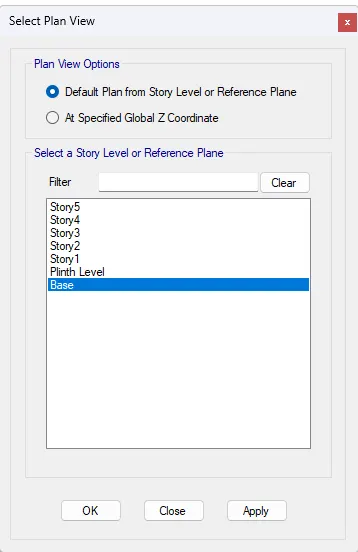
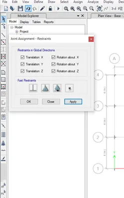
168. Click Assign -> Joints -> Restraints
169. Change it to fixed
171. Click run analysis