REINFORCEMENT DETAILING Of COLUMNS From ETABS OUTPUT
Objective /Aim:
In this ETABS project, our task is to analyze and redesign the Reinforced Concrete (RCC) moment-resisting frame in two columns located at grid intersection 3A and 3B. This analysis and re-design will encompass the entire structure, from the foundation to the terrace level. The design will be carried out in accordance with IS 13920-2016 standards.
Background:
In the document, we have provided specific information regarding the longitudinal reinforcement of the two columns. Additionally, we have illustrated the arrangement of shear reinforcement and provided details about the overlapping of reinforcement bars. These details adhere to the special confining zone requirements outlined in clause 8.1 of IS 13920-2016.
Procedure:
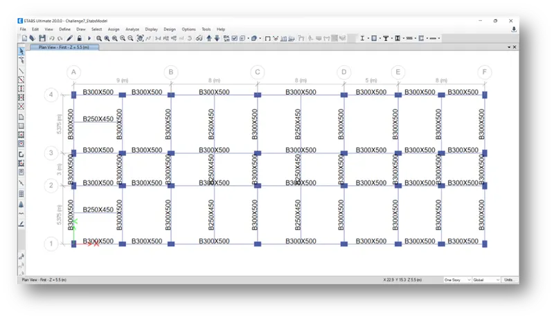
Step (i): Open the Provided Model.
1. Launch the ETABS software.
2. Open the given model file.
3. Review the model for accuracy and completeness.
Step (ii): Column Analysis.
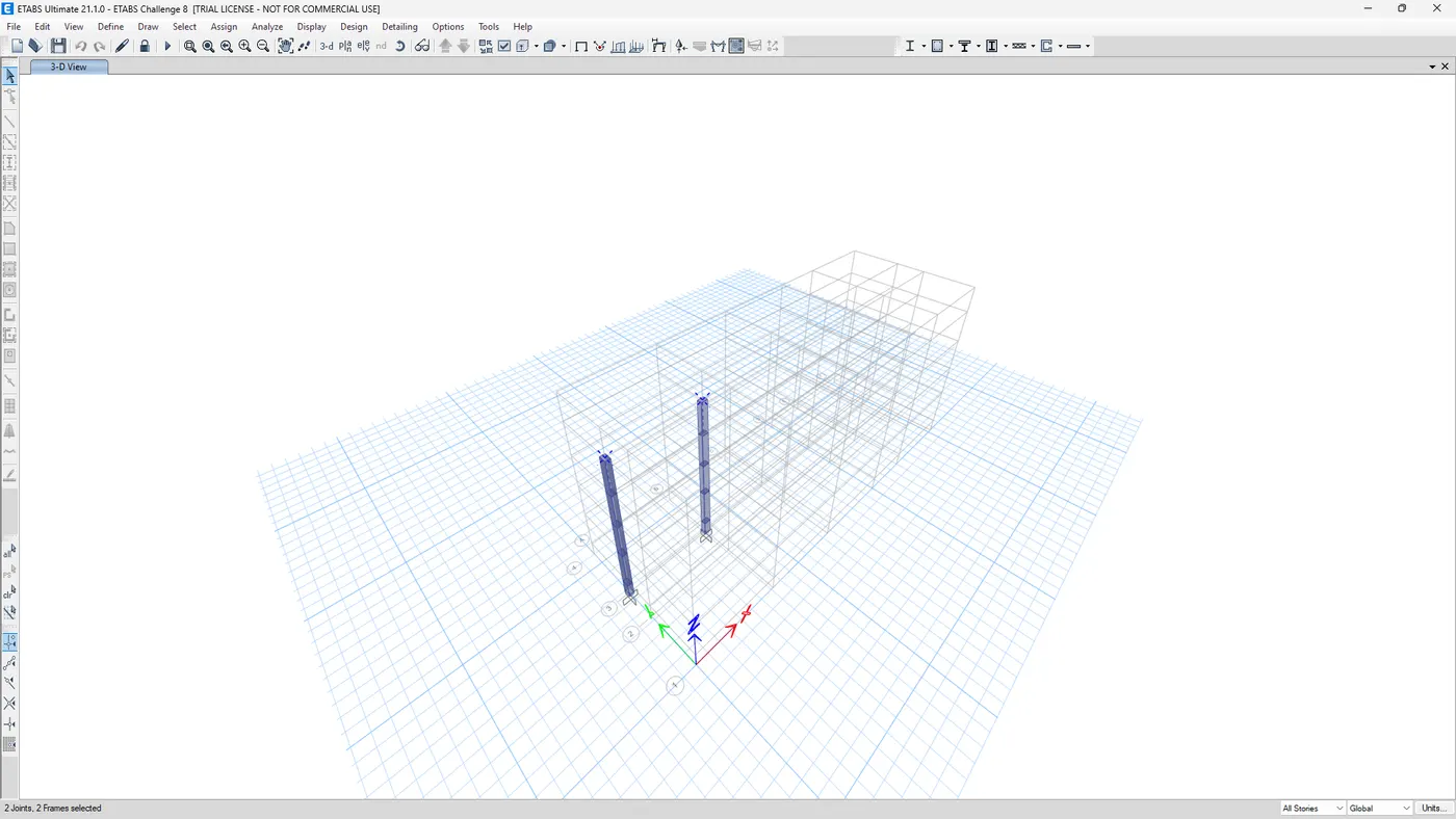
4. Choose the column intersection at 3A and 3B, spanning from the terrace level down to the foundation.
5. Execute the analysis by clicking the "Run" button. This will display both the maximum and minimum deflections at the base.
Step(iii): Reinforcement Details.
6. Click on the "Concrete Frame Design" icon.
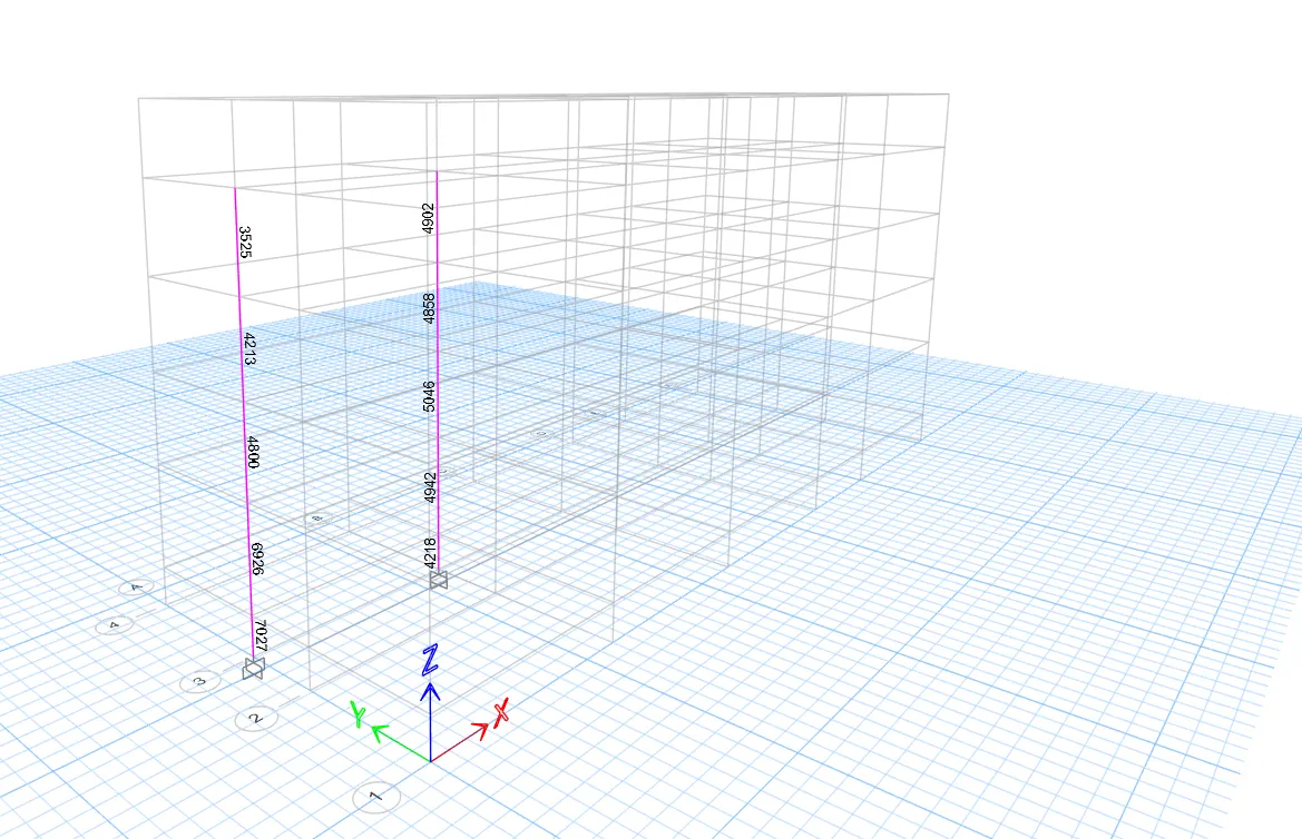
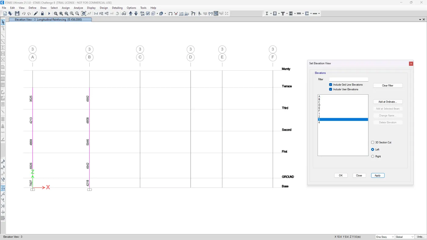
7. This will reveal the longitudinal reinforcement details of the column.
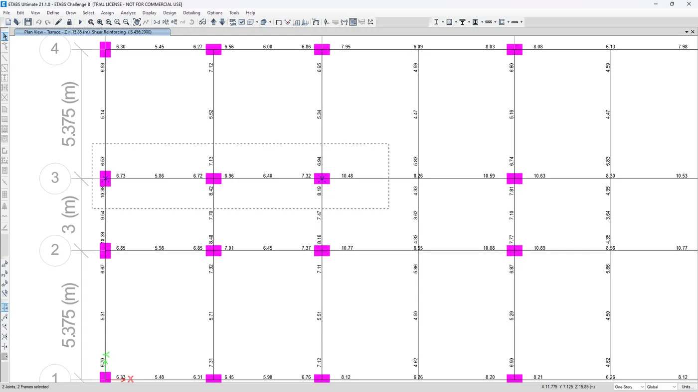
8. Choose the elevation view along grid 3.
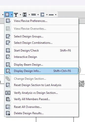
9. Open the "Concrete Frame Design" menu and select "Display Design Information" from the dropdown.
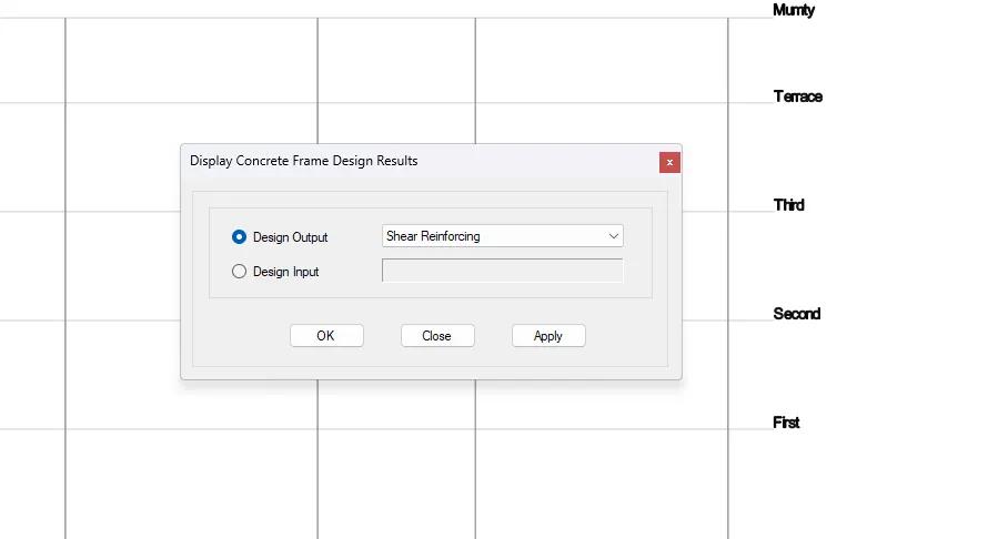
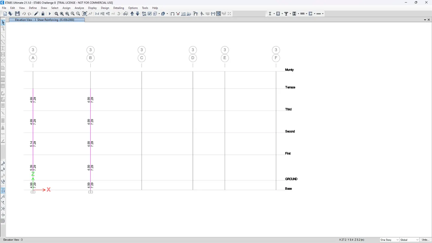
10. To view shear reinforcement details, select the option for displaying concrete frame design.
Step(iv): Reinforcement Design.
11. Obtain the longitudinal and shear reinforcement details for the column at Grid-3A and 3B from ETABS (450X650).
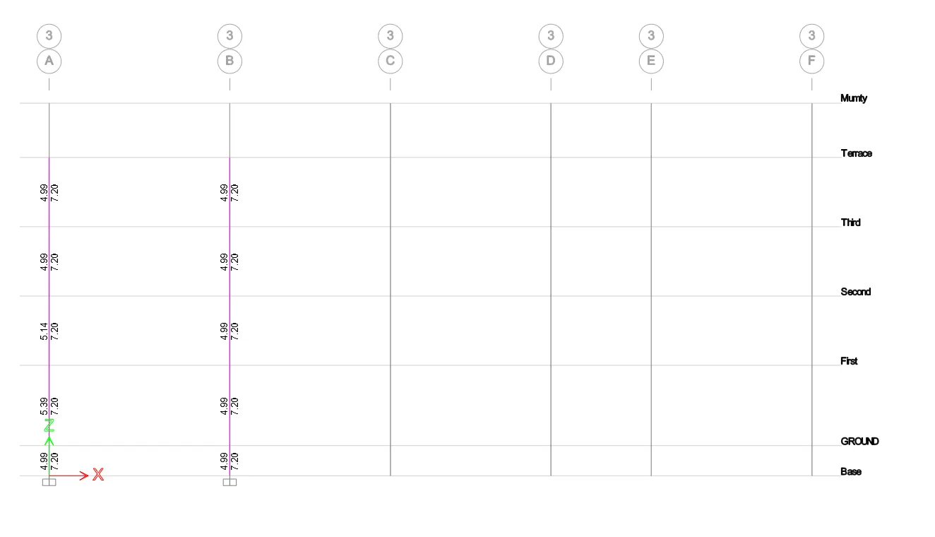
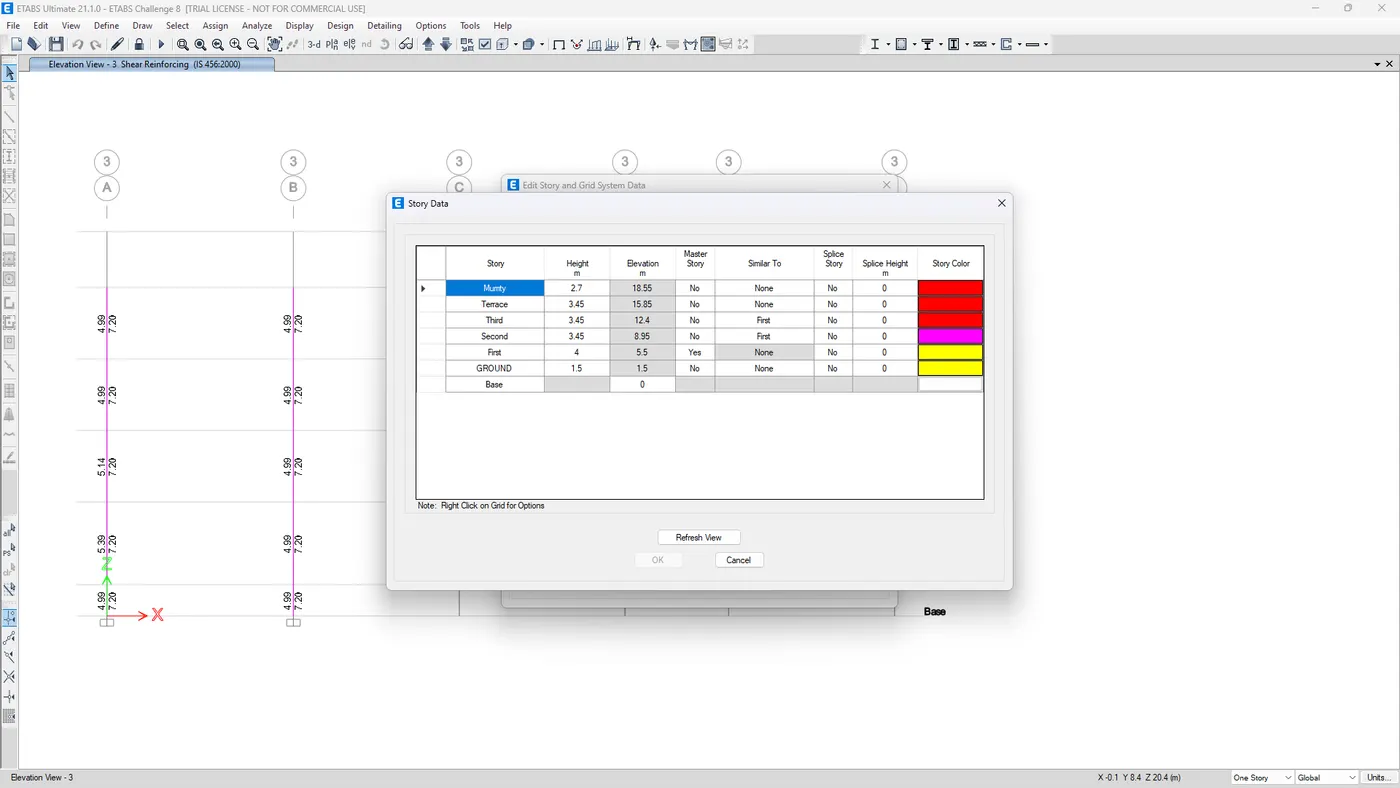
Column Elevation on Each Storey
Special Confining Reinforcement as per IS 13920-2016 (Clause 8.1)
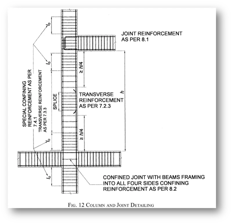
Minimum Length (L_o) should not be less than:
- The larger dimension of the column
- One-sixth of the clear span of the column
- 450 mm
Confinement spacing should not exceed:
- One-fourth of the smaller dimension of the column
- 6 times the diameter of the main reinforcing bars in the column
- 100 mm
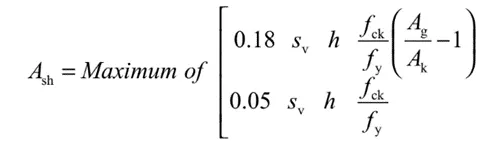
The quantity of confinement reinforcement bar:
GRID A:
From Base to first floor the maximum Ast is
So we can provide 8 no's of 32 mm diameter bar
= 6430.72 mm2
also we can provide 2 no's of 20 mm diameter bar
= 628 mm2
8 no's of 32 mm+2 no's of 20 mm
=7058.72 mm2>7027 mm2
GRID B:
From Base to Terrace floor the maximum Ast
So , Provide 8 bars of 25 mm diameter for the column
= 3927mm2
Provide 2 bars of 32 mm diameter for the column
= 1607.68mm2
Therefore;
Provide 8 bars of 25 mm diameter for the column + Provide 4 bars of 20 mm diameter for the column
= 3927 + 1607.68
= 5534 mm2>5046
- The design and detailing process for the specified column reinforcement at grid intersections 3A and 3B, extending from the foundation to the terrace level, has been successfully completed in accordance with the provisions outlined in IS 13920:2016, specifically addressing clause 8.1.
- This means that the reinforcement has been meticulously planned and documented to meet the structural requirements and standards set forth in the mentioned code.