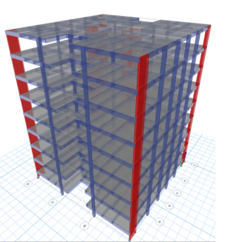
STRUCTURAL MODELLING USING ETABS 2018
Aim/Objective: The aim of the project is to create a detailed digital representation (model) of a residential building and then perform a thorough analysis using a software called ETABS
Procedure:
Step 1:
1. Begin by launching the Etab software. Then, go to the "File" menu and choose "New Model."
2. This action will open a new tab. From there, select the option that says Use Built-in Settings.
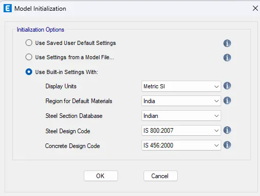
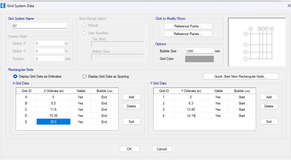
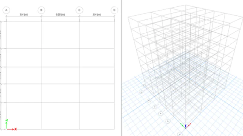
3. Next, proceed to choose the "grid" option, and make the necessary adjustments in the grid system data settings.
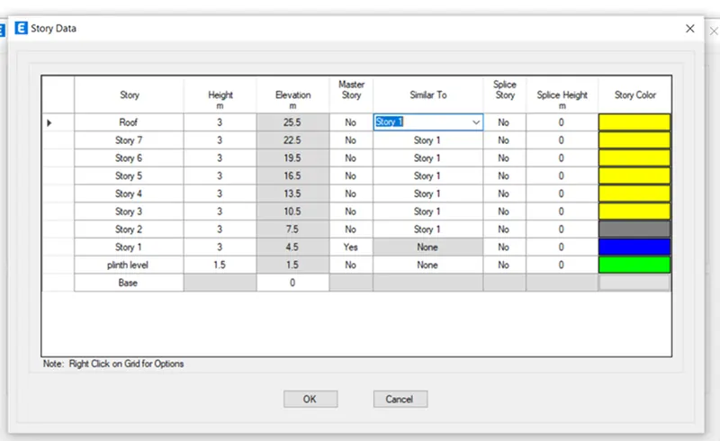
4. Once you've configured the grid settings, proceed to include the seven stories in the story data table.
Step 2:
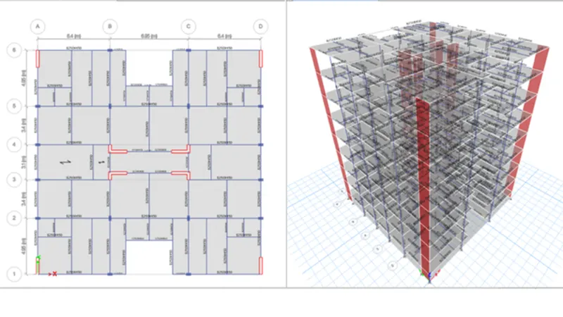
1. Both the plan view and the 3D view are now visible.
Step 3:
1. Go to the "Define" menu option and select "Material Properties."
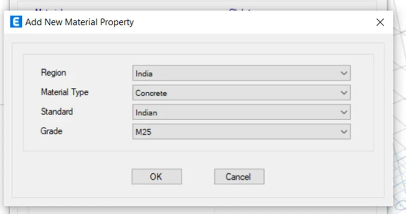
2. Choose the concrete material and set it to M25 grade, with the standard specified as Indian.
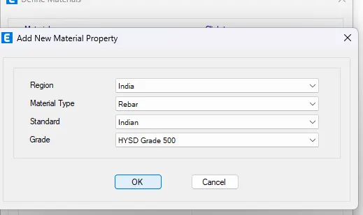
3. To add a new material type, select "Rebar" and set the grade to HYSD 500.
4. Afterward, verify the material properties.
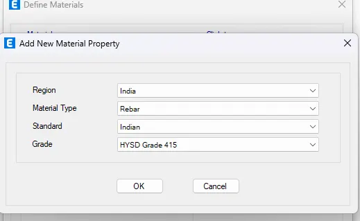
5. Introduce a new material property for Rebar with the grade specified as HYSD 415.
6. Then, verify the material properties.
Step 4:
1. After configuring the material properties, proceed to the "Section Properties" and opt for the "Frame Section" option.
2. In the frame section settings, introduce a new property. Within that tab, choose the "Rectangular shape" and set it as a concrete type.
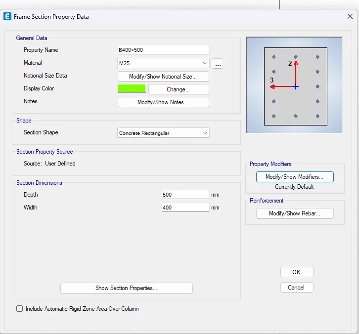
3. Add the beam size as B400x500, and select "Modify/Show Modifiers" to adjust and display the rebar configuration.
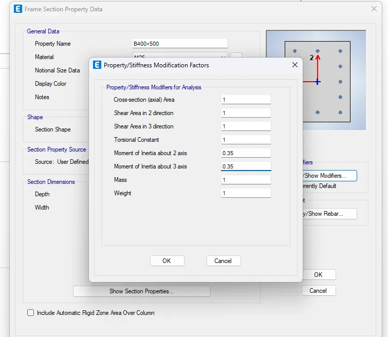
4. Under the stiffness modification factor, set the moment of inertia about the 2-axis to 0.35, and do the same for the moment of inertia about the 3-axis, also setting it to 0.35.
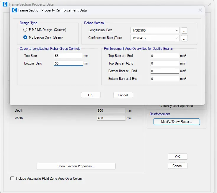
5. After choosing the "Modify/Show Rebar" option, designate the design type as M3, specifically for beam number 9.
6. For the longitudinal bars, select HYSD500, and for the confinement bars, opt for HYSD 415.
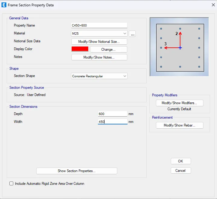
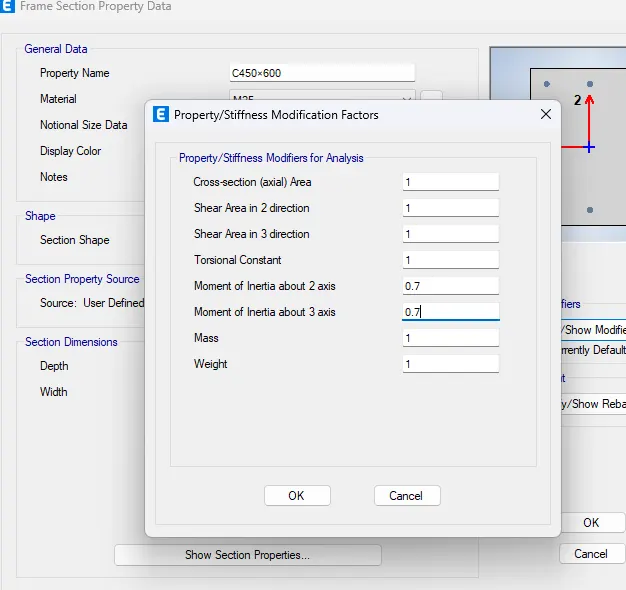
7. Introduce a new section property labeled as C450x600.
8. Under the stiffness modification factor, set the moment of inertia about the 2-axis to 0.7, and do the same for the moment of inertia about the 3-axis, also setting it to 0.7.
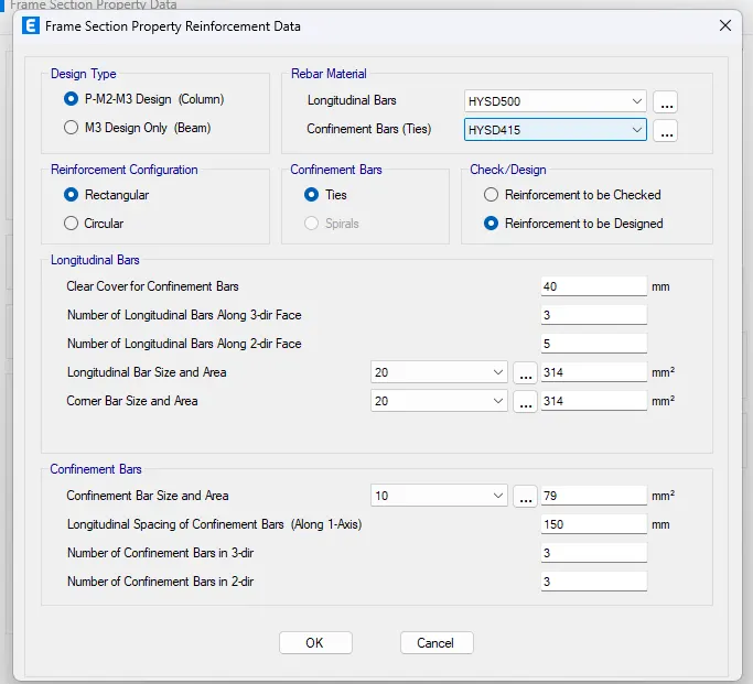
9. Following the selection of the "Modify/Show Rebar" option, choose the design type as P-M2-M3, specifically for columns.
10. For the longitudinal bars, opt for HYSD500, and for the confinement bars, select HYSD 415
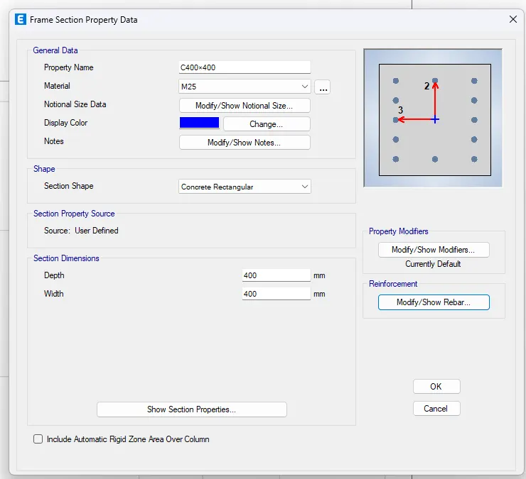
11. Once more, introduce a new section property labeled as C400x400.
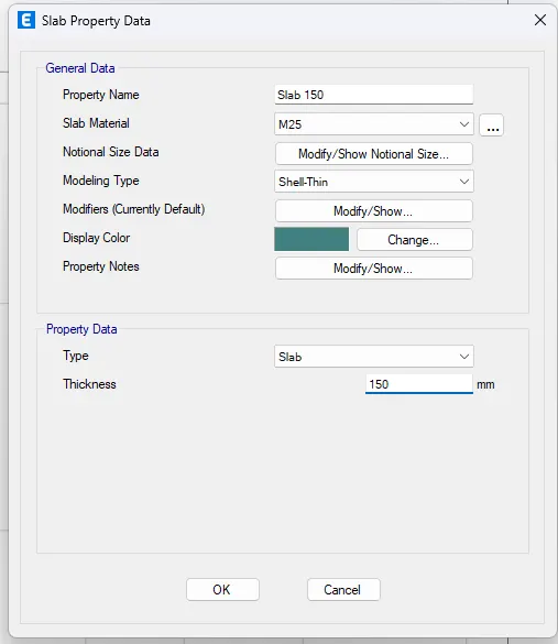
11. Navigate to the "Section" option and choose "Slab Section Property."
12. Click on "Modify/Show Property."
13. Set the slab property to "Slab with 150mm thickness" and then click "OK."
14. For the staircase, once again, add a slab property with a thickness of 200mm.
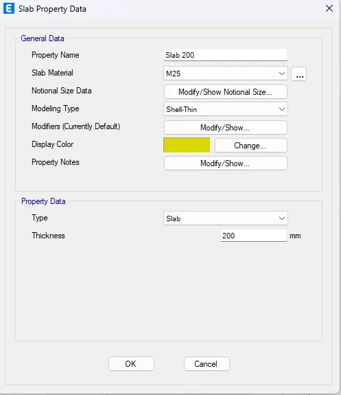
15. Introduce a new wall property labeled as "Wall 300mm".
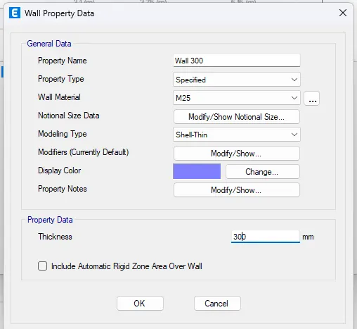
Step 5:
1. Proceed by adding columns using the "Quick Draw Column" option.
2. Following that, incorporate beams using the "Quick Draw Beam" option.
Step 6:
1. Utilize the "Quick Draw Beam" option to sketch the secondary beam.
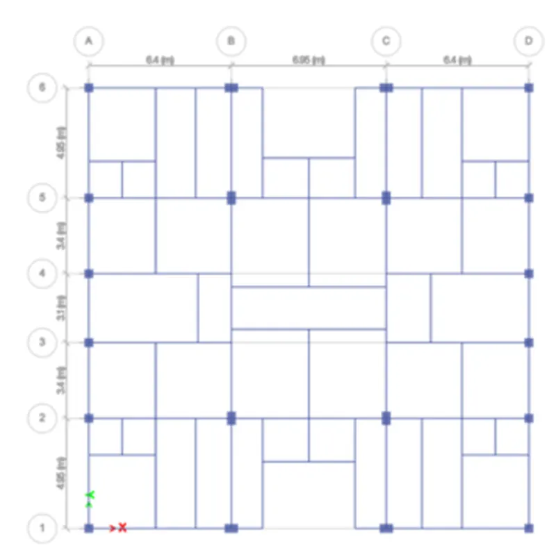
Step 7:
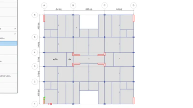
1. Draw the shear wall in the plan view using the "Draw Wall" option.
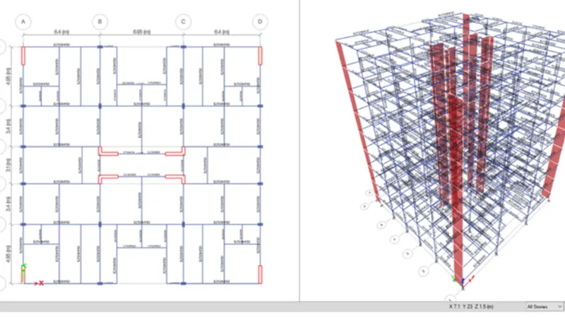
Step 8:
1. Incorporate slabs using the "Quick Draw Floor/Wall" option.
Step 9:
1. Choose the "Base Plan" option.
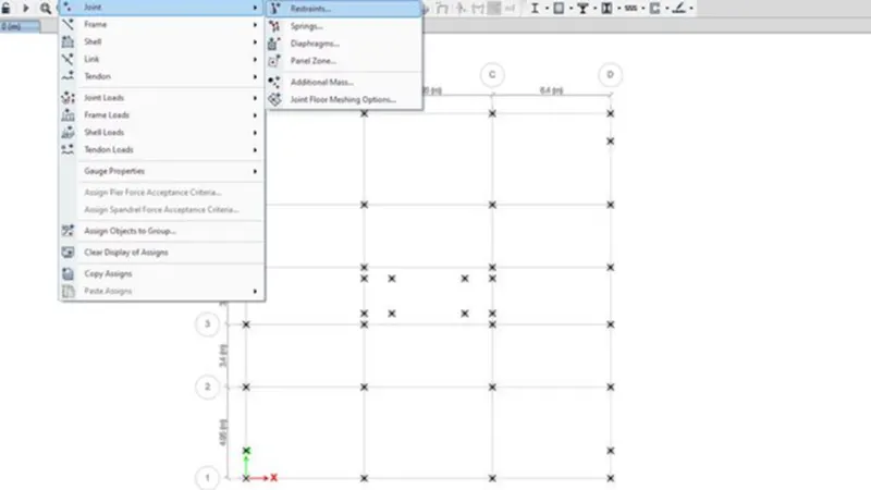
2. Select all the joints.
3. Then, go to the "Joints" option and choose "Restraints."
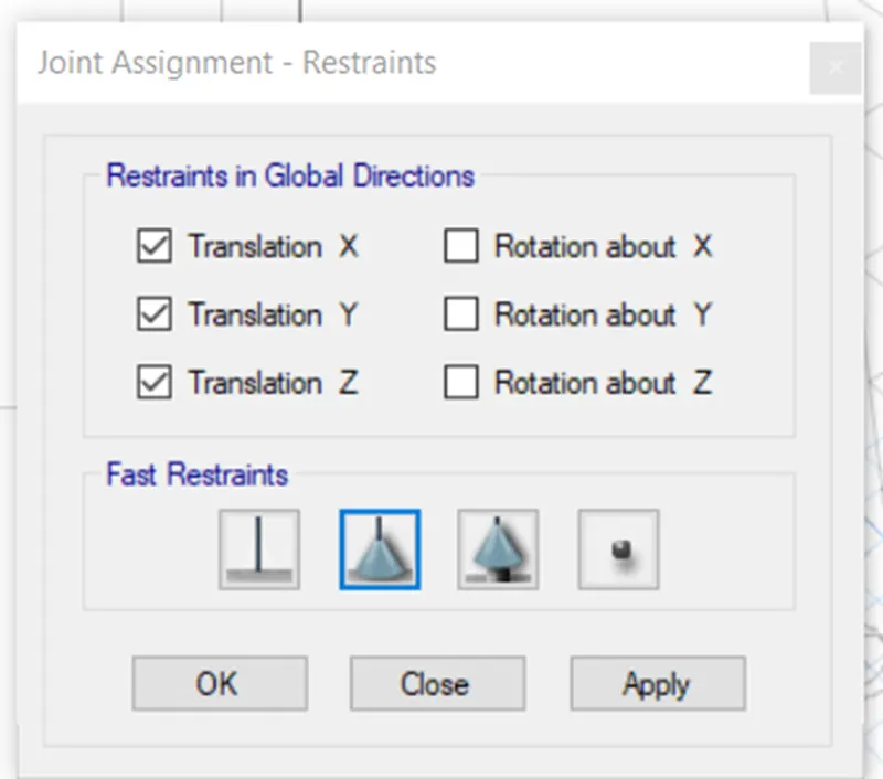
4. Opt for a "Pinned Support" and click "Apply" followed by "OK."
Step 10:
1. Go to the "Define" option.
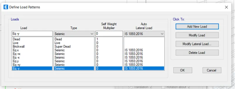
2. Add load patterns.
3. Include the following loads:
- Dead load
- Live load
- Brickwall load
- Earthquake load
Step 11:
1. Proceed to add a distributed load. In the "Frame Load" section, choose "Brickwall" as the load pattern, and set the uniform load value to 3.5 kN/m.
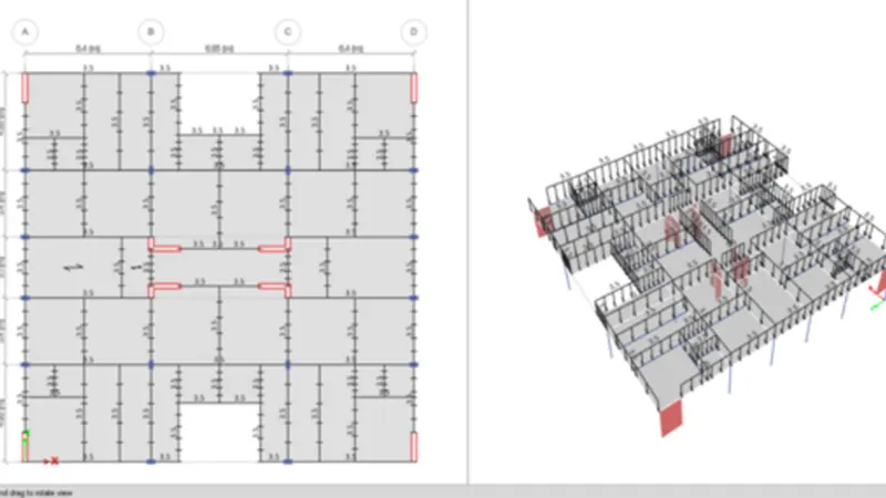
2. Select the "Assign" option, then choose "Shell Load," and from there, select "Uniform."
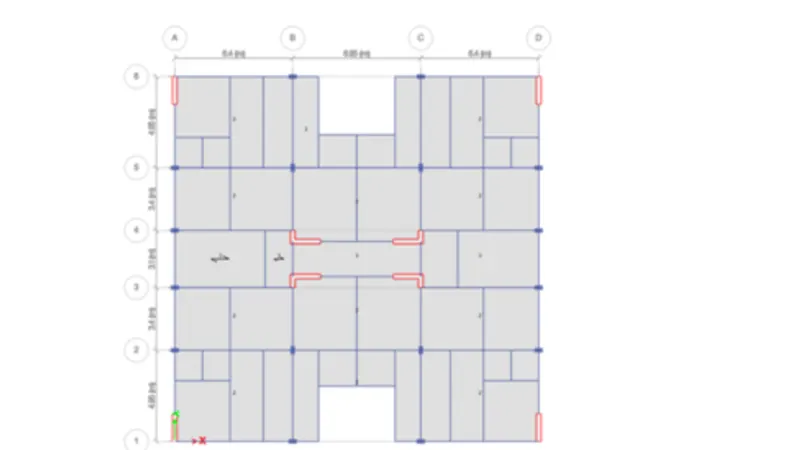
3. Add a live load of 3 kN/m⊃2; for the staircase and lift areas.
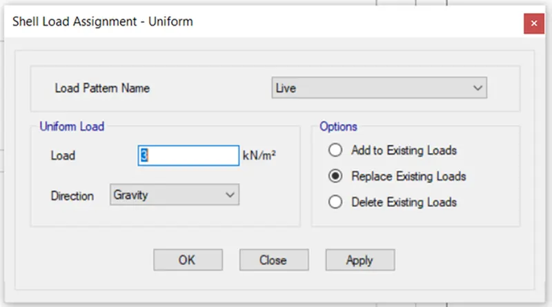
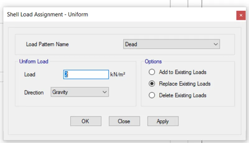
4. Once more, include a live load of 2 kN/m⊃2; for the entire building.
Step 12:
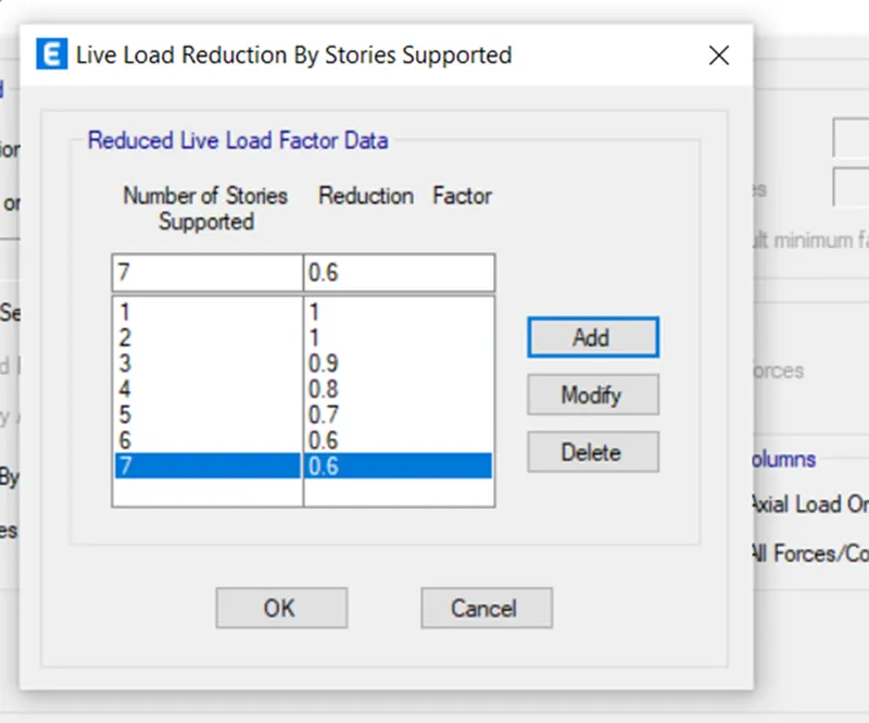
1. Navigate to the "Design" option.
2. Select the live load reduction factor.
3. Decrease the live load by 10% as the reduction factor.
Step 13:
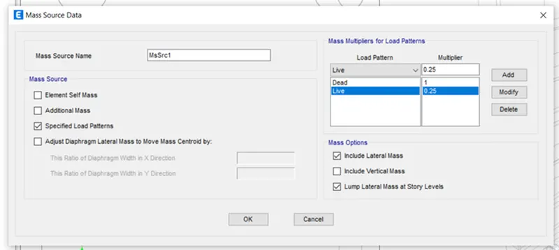
1. Go to the "Define" option and select "Mass Source."
2. Include the load pattern in the mass source data.
Step 14:
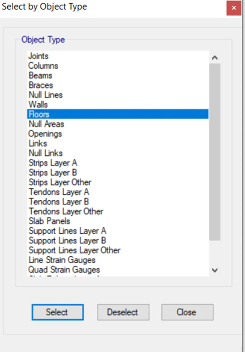
1. Choose the "Object Type" option from the "Select" menu.
2. A new tab will appear. Within it, select "Floors," then proceed to choose and close the selection.
Step 15:
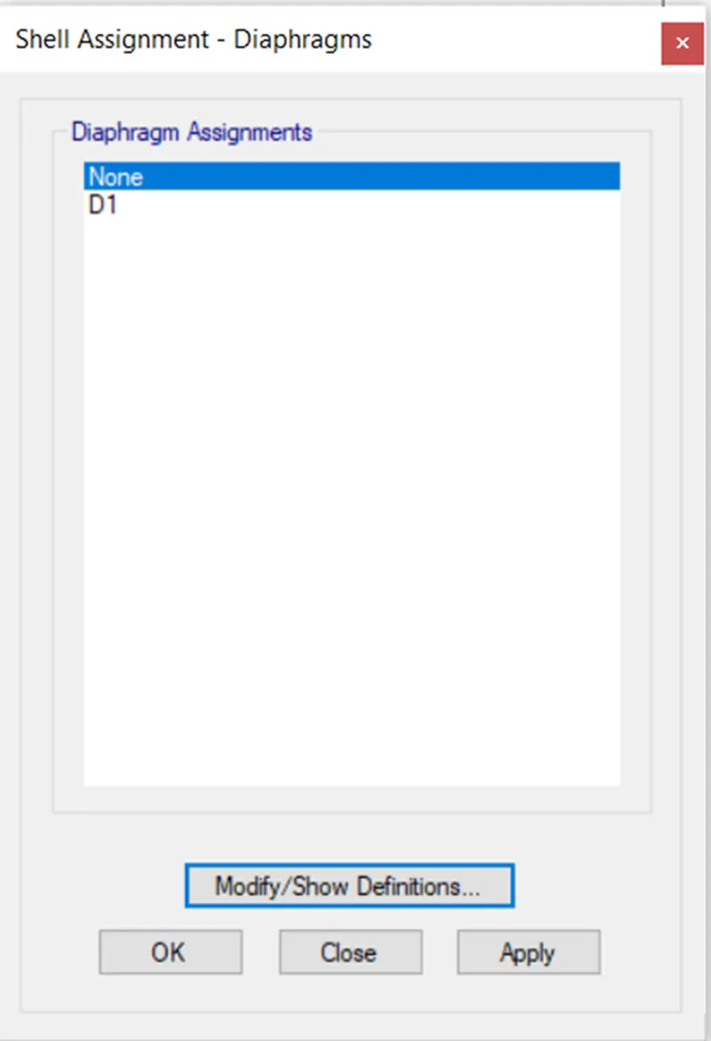
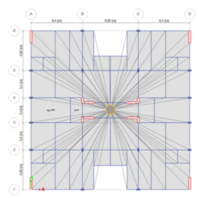
1. Afterward, choose "Diaphragms" from the "Shell" option. A new tab will emerge.
2. Within it, select "D1" and click on "Apply" before closing.
Step 16:
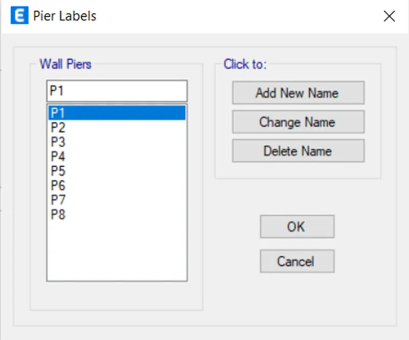
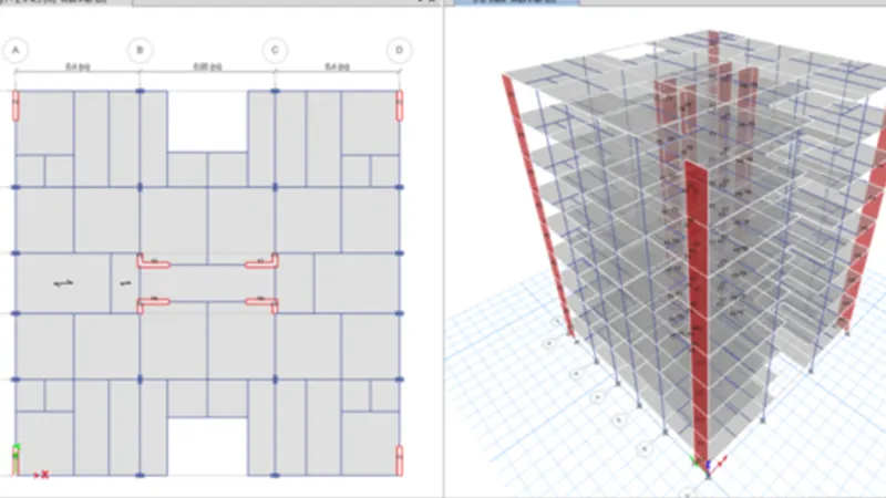
1. Proceed by selecting the "Pier Label" from the "Shell" option.
2.Then, assign the names "p1," "p2," "p3," "p4," "p5," "p6," and "p7" for the shear walls.
Step 17:
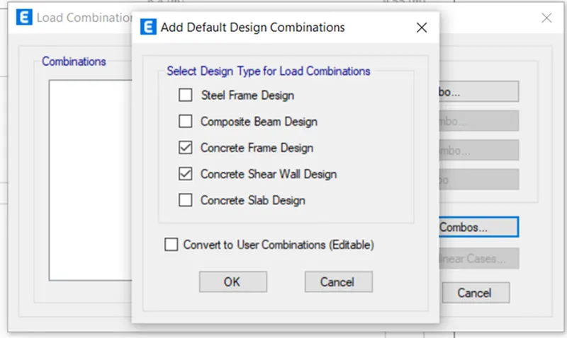
1. Next, go to the "Define" tab and select "Load Combinations."
2. Within that, choose the option to "Add Default Design Combo."
3. Afterward, select both "Concrete Frame Design" and "Concrete Shear Wall Design."
Step 18:
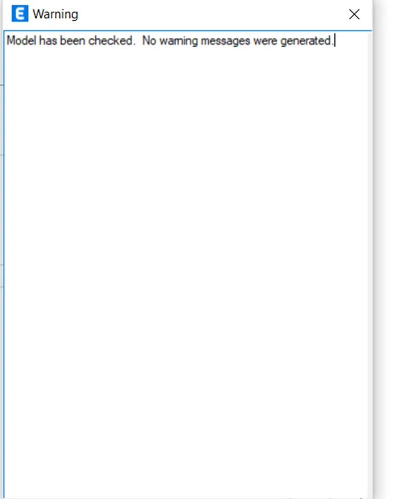
1. Verify the model by clicking on the "Check Model" option from the "Display" menu.
2. The model will be examined, and a warning message will be displayed if any issues are found.
Step 19:
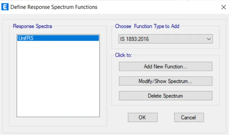
1. Go to the "Define" option, then select "Function," and choose "Response Spectrum."
2. In the new tab, pick "IS 1893-2016" from the function type options. Then, select "Modify/Show Spectrum."
3. In the subsequent tab, provide the name "IS FUNCTION" for the spectrum.
Step 20:
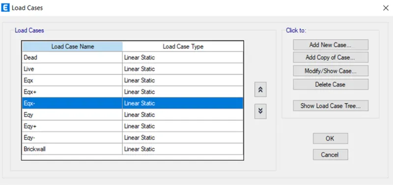
1.Proceed by selecting "Load Cases" from the "Define" option.
2. A load case tab will appear.
3. Within it, choose "Add New Case" and proceed to input the details of the load case data.
Step 21:
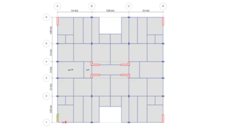
Now, initiate the analysis by clicking on the "Run Analysis" button.
Step 22:
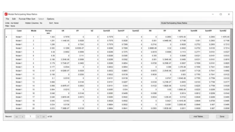
1. From the "Display" option, choose "Show Table."
2. Then, select "Analysis Result-Structure Output," followed by "Base Reactions," and click "OK."
3. This will display the base reaction table.
Step 23:
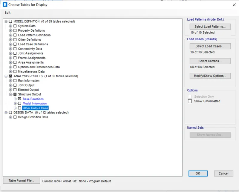
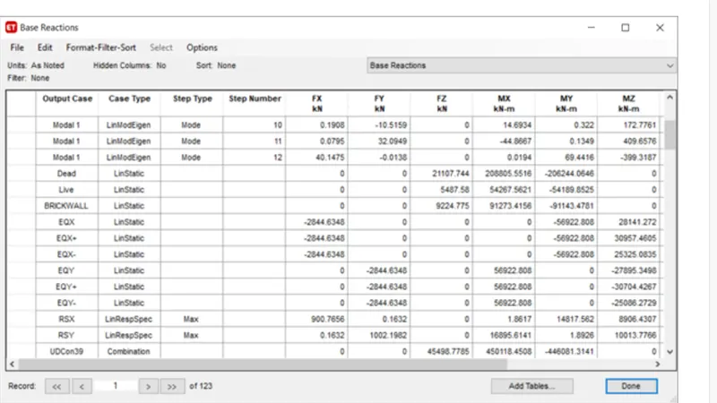
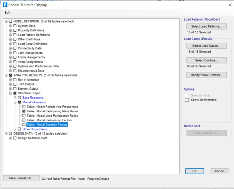
1. Navigate to the "Display" menu and choose "Show Table."
2. Then, opt for "Analysis Result-Structure Output," followed by "Base Reactions," and click "OK."
3. This will display the base reaction table.
Step 24:
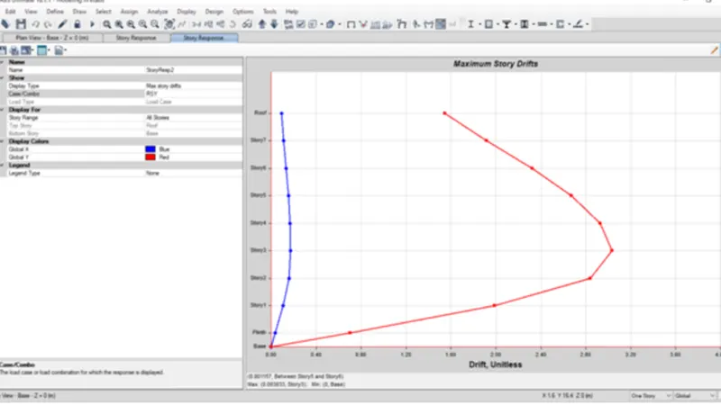
1. Choose "Story Response Plot" from the "Display" option.
Step 25:
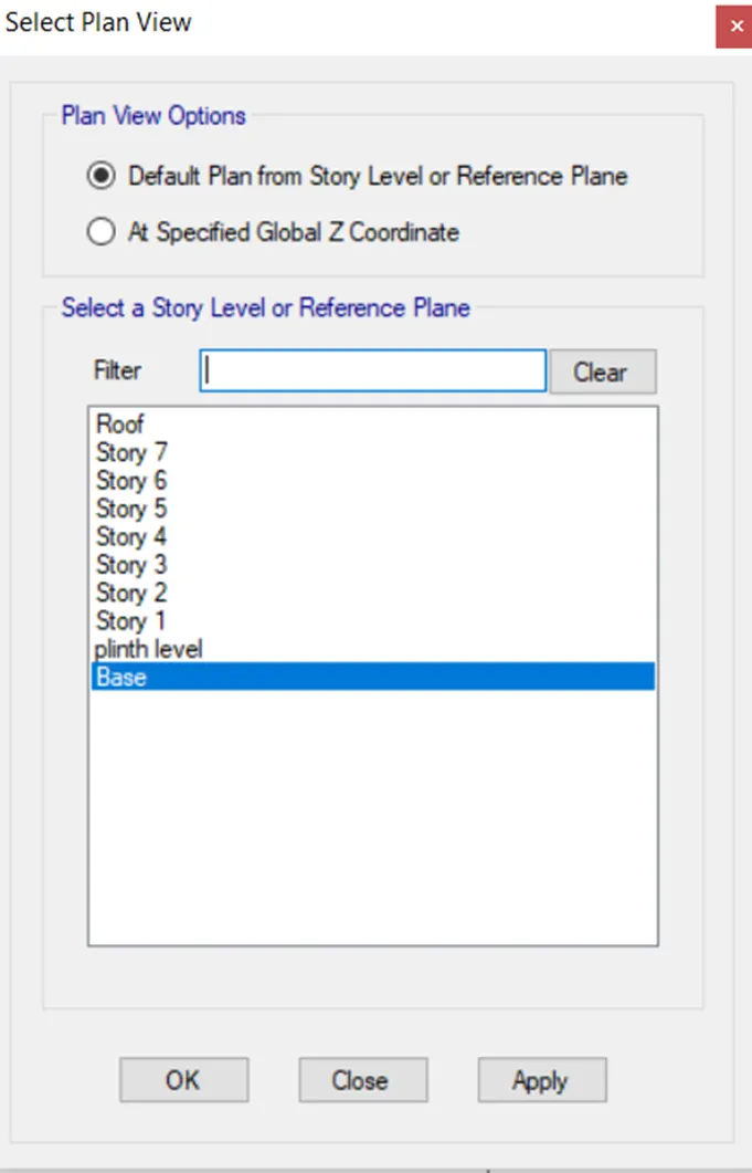
1. Select the "Plan View" option and open the base floor plan.
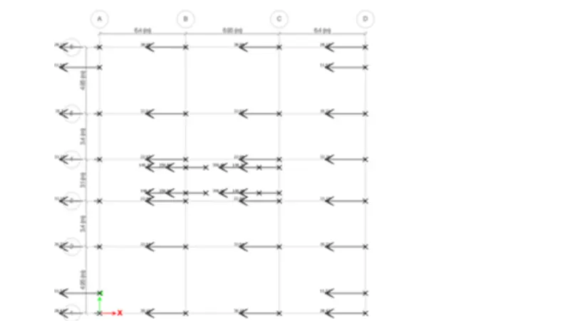
2. Open the reaction tab and choose the "Earthquake Load."
3. The base shear reaction will now be displayed.
Result:
* The G+7 residential project is now complete.
* It included detailed modeling, load simulations, and thorough assessments.
* Considerations for mass distribution, diaphragms, and load combinations were made.
* Rigorous checks were performed, ensuring the building's safety.
* In summary, the G+7 building is now secure and dependable.